EP2371756A2 - Rückfallstütze - Google Patents
Rückfallstütze Download PDFInfo
- Publication number
- EP2371756A2 EP2371756A2 EP11002368A EP11002368A EP2371756A2 EP 2371756 A2 EP2371756 A2 EP 2371756A2 EP 11002368 A EP11002368 A EP 11002368A EP 11002368 A EP11002368 A EP 11002368A EP 2371756 A2 EP2371756 A2 EP 2371756A2
- Authority
- EP
- European Patent Office
- Prior art keywords
- push rod
- carbon fiber
- jib
- support
- fallback
- Prior art date
- Legal status (The legal status is an assumption and is not a legal conclusion. Google has not performed a legal analysis and makes no representation as to the accuracy of the status listed.)
- Granted
Links
Images


Classifications
-
- B—PERFORMING OPERATIONS; TRANSPORTING
- B66—HOISTING; LIFTING; HAULING
- B66C—CRANES; LOAD-ENGAGING ELEMENTS OR DEVICES FOR CRANES, CAPSTANS, WINCHES, OR TACKLES
- B66C23/00—Cranes comprising essentially a beam, boom, or triangular structure acting as a cantilever and mounted for translatory of swinging movements in vertical or horizontal planes or a combination of such movements, e.g. jib-cranes, derricks, tower cranes
- B66C23/62—Constructional features or details
- B66C23/82—Luffing gear
-
- B—PERFORMING OPERATIONS; TRANSPORTING
- B66—HOISTING; LIFTING; HAULING
- B66C—CRANES; LOAD-ENGAGING ELEMENTS OR DEVICES FOR CRANES, CAPSTANS, WINCHES, OR TACKLES
- B66C23/00—Cranes comprising essentially a beam, boom, or triangular structure acting as a cantilever and mounted for translatory of swinging movements in vertical or horizontal planes or a combination of such movements, e.g. jib-cranes, derricks, tower cranes
- B66C23/62—Constructional features or details
- B66C23/64—Jibs
- B66C23/66—Outer or upper end constructions
-
- B—PERFORMING OPERATIONS; TRANSPORTING
- B66—HOISTING; LIFTING; HAULING
- B66C—CRANES; LOAD-ENGAGING ELEMENTS OR DEVICES FOR CRANES, CAPSTANS, WINCHES, OR TACKLES
- B66C23/00—Cranes comprising essentially a beam, boom, or triangular structure acting as a cantilever and mounted for translatory of swinging movements in vertical or horizontal planes or a combination of such movements, e.g. jib-cranes, derricks, tower cranes
- B66C23/62—Constructional features or details
- B66C23/64—Jibs
- B66C23/70—Jibs constructed of sections adapted to be assembled to form jibs or various lengths
- B66C23/701—Jibs constructed of sections adapted to be assembled to form jibs or various lengths telescopic
- B66C23/702—Jibs constructed of sections adapted to be assembled to form jibs or various lengths telescopic with a jib extension boom
-
- B—PERFORMING OPERATIONS; TRANSPORTING
- B66—HOISTING; LIFTING; HAULING
- B66C—CRANES; LOAD-ENGAGING ELEMENTS OR DEVICES FOR CRANES, CAPSTANS, WINCHES, OR TACKLES
- B66C23/00—Cranes comprising essentially a beam, boom, or triangular structure acting as a cantilever and mounted for translatory of swinging movements in vertical or horizontal planes or a combination of such movements, e.g. jib-cranes, derricks, tower cranes
- B66C23/88—Safety gear
- B66C23/92—Snubbers or dashpots for preventing backwards swinging of jibs, e.g. in the event of cable or tackle breakage
Definitions
- the present invention relates to a fall arrestor for a jib which is mounted on a jib head of a crane with at least one push rod which is disposed between the jib and the jib head and limits a relieving movement of the jib.
- fallback supports are known with at least one push rod, which is arranged between the needle boom and the boom head and a fallback movement so limited to the rear of the jib.
- pressure rods are made of a steel tube, resulting in a high weight of the construction and a correspondingly reduced load capacity of the crane.
- Object of the present invention is therefore to provide a fallback support available, through which higher payloads can be achieved, in particular by reducing the weight of the push rod.
- a fallback support according to claim 1.
- This is a fall arrest support for a jib which is attached to a jib head of a crane with at least one push rod which is disposed between the jib and the jib head and limits a fallback movement of the jib.
- the push rod comprises a fiber composite tube. The use of such a fiber composite tube as a push rod allows a significant weight reduction at the same compressive strength of the fallback support. As a result, the load of the boom can be increased accordingly or can be used a correspondingly larger and longer boom.
- the push rod comprises an aluminum tube with a reinforcement made of carbon fibers.
- a reinforcement made of carbon fibers The use of such an aluminum-carbon fiber composite as a push rod leads on the one hand to a high-strength yet lightweight push rod.
- the use of an aluminum tube allows easy connection of the push rod to the rest of the construction, eg. B. over tails, which are easily connected to the aluminum tube. The often problematic in fiber reinforced plastic pipes connection to the further construction is therefore considerably simplified.
- the push rod has a plurality of extending in the longitudinal direction of the push rod carbon fiber slats. Through the carbon fiber slats that can be
- Aluminum tube are reinforced against buckling, so that the compressive strength increases significantly.
- the fiber direction of the carbon fibers in the carbon fiber slats advantageously also extends in the longitudinal direction of the push rod.
- the carbon fiber blades surround the aluminum tube in the circumferential direction with intervals between them.
- weight can be saved because no continuous, running in the longitudinal direction of the aluminum tube carbon fiber reinforcement is used, but the carbon fiber slats each have a certain distance between each other.
- carbon fiber slats also facilitates the production of the push rod according to the invention, since these can be manufactured separately and then connected to the aluminum rod.
- the carbon fiber fins are arranged in a central region of the push rod and do not extend into the end regions of the push rod. This, in turn, weight can be saved, while the particularly kink-prone middle region of the push rod is reinforced by the carbon fiber fins.
- the length of the central region with the carbon fiber lamellae is between 10% and 90% of the total length of the push rod, moreover advantageously between 20% and 80%, furthermore advantageously between 25% and 70% and furthermore advantageously between 30% and 50%. the total length.
- the carbon fiber fins have a thickness in the radial direction, which is between 50% and 300% of the wall thickness of the aluminum tube be advantageously between 80% and 250%, more advantageously between 100% and 200%.
- more than three carbon fiber fins are provided, further advantageously more than five carbon fiber fins. Further advantageously, the number of carbon fiber fins is between three and twenty, more advantageously between five and twelve.
- the push rod may have a wrapping of carbon fibers in the circumferential direction at least in a partial region. Such a winding of carbon fibers allows a particularly effective damping of the push rod.
- the wrapping of carbon fibers extends beyond the area of the carbon fiber slats.
- the winding of carbon fibers extends over more than 50% of the total length of the aluminum tube, moreover advantageously more than 70%, moreover advantageously more than 85%.
- the thickness of the coiling of carbon fibers in the radial direction is less than 70% of the wall thickness of the aluminum tube and / or the thickness of the carbon fiber fins, more advantageously less than 50%, more advantageously less than 30%.
- the thickness of the wrapping is more than 5% of the wall thickness of the aluminum tube, moreover advantageously more than 10%.
- no carbon fiber wrap is provided in the end regions of the aluminum tube.
- the carbon fiber fins are arranged on the winding of carbon fibers.
- the push rod thus has the following structure from inside to outside: an aluminum tube, one of the wrapping Carbon fiber layer formed in the circumferential direction and arranged on this wrapping carbon fiber fins.
- an aluminum-carbon fiber composite tube allows a particularly simple connection of the push rod via end pieces, which are connected to the aluminum tube.
- the fallback support has at least one first end piece, which allows a bolting of the fallback support.
- this end piece for this purpose at least one tab with a bore through which a bolt can be passed.
- the fallback support on a second end piece, which engages positively in the load case in a final recording on the jib or on the boom head.
- the push rod according to the invention has a compressive strength of more than 500 kN.
- the push rod according to the invention can be used not only as a fallback support for the jib of a crane, but is everywhere used where a high strength is required at low weight.
- the present invention therefore further comprises a push rod made of an aluminum tube with a carbon fiber reinforcement.
- a push rod made of an aluminum tube with a carbon fiber reinforcement.
- Such an aluminum tube with a reinforcement of carbon fibers can be used wherever high forces are to be absorbed at low weight.
- the push rod is carried out as already described above.
- the push rod has several, in the longitudinal direction the push rod extending carbon fiber fins on.
- the carbon fiber slats are designed as shown above.
- the push rod on a winding of carbon fibers in the circumferential direction is carried out as already described above.
- the fallback support has two end pieces, which are connected to the ends of the aluminum tube.
- the se end pieces serve the connection to the further construction.
- the present invention further comprises a grid construction, in particular a cantilever, with a fallback support and / or a pushrod as set forth above.
- the present invention comprises a boom of a crane, on which a needle boom is arranged, wherein according to the invention between the needle boom and the boom head a fallback support according to the invention is arranged.
- the present invention also quite generally includes grid structures in which one or more push rods according to the invention are used.
- the present invention further includes a crane having a fall-back support and / or a push rod and / or grid construction as set forth above.
- a fallback support in accordance with the present invention is disclosed in U.S. Pat FIG. 1 shown.
- the Anschzhou a jaw 1 is shown, which is arranged on a boom head 3 on the main boom 2 of a crane.
- Both the jib 1 and the main boom 2 consist of a grid construction.
- jib 1 and main boom 2 are constructed of lattice pieces.
- the jib 1 is pivotally mounted about a horizontal axis 4 on the boom head 3. In the event of a load break or heavy gusts of wind, the jib can be pushed from the front to the rear, which can result in very high forces. These forces must be absorbed by the fallback support.
- fall arrest has two push rods 10, which are arranged between the pivot piece of the jaw 1 and the boom head 3.
- the push rods 10 are a fiber composite tube made of an aluminum tube and a carbon fiber reinforcement, which in spite of the forces occurring during a load rupture or violent gusts of wind its compared to a steel tube can absorb significantly lower weight.
- the structure of the push rods is explained in more detail later.
- the fallback support in FIG. 1 furthermore two hydraulic cylinders 6 coupled via gas springs, which are arranged between the boom head 3 and the guy support 5.
- the entire retreating moment of the guy blocks 5 is thus compensated via the gas springs 6.
- the retreating moment of the jib is absorbed by the pressure rods according to the invention, which form rigid pressure rods.
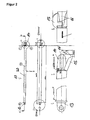
- the present invention in the fallback support used push rods 10 are in FIG. 2 shown in more detail.
- the push rod 10 in this case has an aluminum-carbon fiber composite tube 20, which will be described in more detail below.
- At the ends of this aluminum-carbon composite tube 20 has end pieces 13 and 14, which serve the connection to the needle boom or to the boom head.
- the end piece 13 has two tabs with a bore through which a bolt can be performed.
- the end piece 14 has an end opening 16 and a guide element 15.
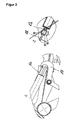
- the articulation of the end pieces 13 and 14 is in FIG. 3 shown.
- the section EE shows how the end piece 14 is secured with a hook-shaped receptacle 17, which is arranged articulated on the boom head.
- the tail 13, however, is bolted via a fork finger connection with the jib.
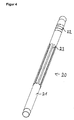
- the fiber composite pipe according to the invention is now in FIGS. 4 and 5 shown in more detail.
- the fiber composite tube can be used as a fallback support of a jib as shown above.
- the push rod according to the invention comprises an aluminum tube 21, which has a reinforcement made of carbon fibers.
- carbon fiber fins 23 provided, which extend in the longitudinal direction of the aluminum tube.
- the carbon fiber slats are arranged outside the aluminum tube and surround this in the circumferential direction, with a certain distance remaining between the individual carbon fiber slats.
- similar carbon fiber fins 23 are used, which are arranged at regular intervals around the aluminum tube around.
- eight carbon fiber slats are used.
- the carbon fiber fins 23 are arranged in a central region of the aluminum tube and do not extend into the end regions.
- the carbon fiber slats have a length which corresponds to approximately 40% of the total length of the aluminum tube 21.
- the carbon fiber slats are arranged centrally with respect to the total length of the push rod, so that in each case approximately equal lengths remain at the two ends of the push rod, in which the carbon fiber slats do not extend.
- the composite pipe according to the invention further comprises a winding 22 made of carbon fibers.
- the carbon fibers are wound in the circumferential direction around the push rod and thus form an effective damping.
- the wrapping extends over a large part of the total length of the aluminum tube 21. Only at the two ends of the aluminum tube is a short distance not surrounded by the winding of carbon fibers.
- the length of the non-wound end regions in the exemplary embodiment is less than 5% of the total length of the aluminum tube.
- the carbon fiber fins 23 are applied to the winding 22 made of carbon fibers.
- the fiber direction in the carbon fiber slats runs parallel to the longitudinal direction of the aluminum tube, so that the buckling strength of the aluminum tube is considerably enhanced by the carbon fiber slats.
- the aluminum tube allows a particularly simple connection with end pieces, over which The aluminum-carbon fiber composite pipe can be connected to the wider structure.
- FIG. 5 the direction of the compressive force F is shown by the arrows, which acts on the push rod according to the invention.
- the push rod according to the invention is designed in the exemplary embodiment so that it withstands a pressure load of more than 500 kN.
- the aluminum tube used has an inner diameter of 100 mm and an outer diameter of 110 mm.
- the aluminum tube thus has a wall thickness of 5 mm.
- the outer diameter of the composite tube in the area of the winding of carbon fibers is 112 mm.
- the carbon fiber wrap thus has a thickness of 1 mm.
- the tube In the field of carbon fiber fins, however, the tube has an outer diameter of 124 mm.
- the carbon fiber blades therefore have a thickness of 6 mm.
- the entire aluminum-carbon fiber composite pipe has a total length of about 2 m.
- the present invention provides the aluminum-carbon fiber composite pipe a particularly strong yet lightweight push rod available. This can be used in particular in a fallback support according to the invention.
- the present invention in addition to the push rod and the fallback support further grid structures such.
Landscapes
- Engineering & Computer Science (AREA)
- Mechanical Engineering (AREA)
- Jib Cranes (AREA)
- Manufacture Of Alloys Or Alloy Compounds (AREA)
Abstract
Description
- Die vorliegende Erfindung betrifft eine Rückfallstütze für einen Nadelausleger, welcher an einem Auslegerkopf eines Kranes angebracht ist, mit mindestens einer Druckstange, welche zwischen dem Nadelausleger und dem Auslegerkopf angeordnet ist und eine Rückfallbewegung des Nadelauslegers begrenzt.
- Für die Rückhaltefunktion von beweglichen oder festen Nadelauslegern sind verschiedene Lösungen bekannt. Zum einen kommen dabei Zugseile mit einer Druckstütze zum Einsatz, welche auf der Vorderseite des Nadelauslegers angeordnet sind und die Rückfallbewegung des Nadelausleger so z. B. beim Reißen des Lastseils begrenzen. Eine solche Anordnung aus Zugseil mit Druckstütze wird auch umgangssprachlich als Affenschaukel bezeichnet. Diese Lösung hat jedoch den Nachteil, dass der Kran mit einem gewissen Abstand zu angrenzenden Gebäudekanten positioniert werden muss, da die Affenschaukel nach vorne hin Platz benötigt.
- Weiterhin sind Rückfallstützen mit mindestens einer Druckstange bekannt, welche zwischen dem Nadelausleger und dem Auslegerkopf angeordnet ist und eine Rückfallbewegung des Nadelauslegers so nach hinten begrenzt. Für solche Rückfallstützen werden dabei Druckstangen aus einem Stahlrohr hergestellt, was zu einem hohen Gewicht der Konstruktion und einer dementsprechend verringerten Traglast des Kranes führt. Zudem kann aufgrund der Masse auch nur ein relativ kürzerer Ausleger aufgerichtet werden.
- Aufgabe der vorliegenden Erfindung ist es daher, eine Rückfallstütze zur Verfügung zu stellen, durch welche sich höhere Traglasten erreichen lassen, insbesondere durch Verringerung des Gewichts der Druckstange.
- Diese Aufgabe wird erfindungsgemäß durch eine Rückfallstütze gemäß Anspruch 1 gelöst. Dabei handelt es sich um eine Rückfallstütze für einen Nadelausleger, welcher an einem Auslegerkopf eines Kranes angebracht ist, mit mindestens einer Druckstange, welche zwischen dem Nadelausleger und dem Auslegerkopf angeordnet ist und eine Rückfallbewegung des Nadelauslegers begrenzt. Erfindungsgemäß umfaßt die Druckstange dabei ein Faserverbundrohr. Der Einsatz eines solchen Faserverbundrohrs als Druckstange ermöglicht eine erhebliche Gewichtsreduktion bei gleicher Druckfestigkeit der Rückfallstütze. Hierdurch kann die Traglast des Auslegers entsprechend erhöht werden bzw. kann ein entsprechend größerer und längerer Ausleger eingesetzt werden.
- Vorteilhafterweise umfaßt die Druckstange dabei ein Aluminiumrohr mit einer Verstärkung aus Kohlefasern. Der Einsatz eines solchen Aluminium-Kohlefaser-Composites als Druckstange führt zum einen zu einer hochfesten und dennoch leichten Druckstange. Zudem erlaubt die Verwendung eines Aluminiumrohrs eine leichte Anbindung der Druckstange an die übrige Konstruktion, z. B. über Endstücke, welche mit dem Aluminiumrohr problemlos verbindbar sind. Die bei faserverstärkten Kunststoffrohren oftmals problematische Anbindung an die weitere Konstruktion ist daher erheblich vereinfacht.
- Vorteilhafterweise weist die Druckstange mehrere, in Längsrichtung der Druckstange verlaufende Kohlefaser-Lamellen auf. Durch die Kohlefaser-Lamellen kann das
- Aluminiumrohr gegen Ausknicken verstärkt werden, so dass sich die Druckfestigkeit erheblich erhöht. Die Faserrichtung der Kohlefasern in den Kohlefaser-Lamellen verläuft vorteilhafterweise ebenfalls in Längsrichtung der Druckstange.
- Vorteilhafterweise ist vorgesehen, dass die Kohlefaser-Lamellen das Aluminiumrohr in Umfangsrichtung mit dazwischen liegenden Abständen umgeben. Hierdurch kann wiederum Gewicht eingespart werden, da keine durchgehende, in Längsrichtung des Aluminiumrohrs verlaufende Kohlefaserverstärkung eingesetzt wird, sondern die Kohlefaser-Lamellen jeweils einen gewissen Abstand zwischen einander aufweisen.
- Vorteilhafterweise werden dabei mehrere identische Kohlefaser-Lamellen eingesetzt, welche jeweils mit gleichem Abstand zueinander das Aluminiumrohr in Umfangsrichtung umgeben.
- Der Einsatz von Kohlefaser-Lamellen erleichtert auch die Herstellung der erfindungsgemäßen Druckstange, da diese separat hergestellt und dann mit der Aluminiumstange verbunden werden können.
- Vorteilhafterweise sind die Kohlefaser-Lamellen in einem mittleren Bereich der Druckstange angeordnet und erstrecken sich nicht in die Endbereiche der Druckstange. Auch hierdurch kann wiederum Gewicht eingespart werden, während der besonders knickanfällige mittlere Bereich der Druckstange durch die Kohlefaser-Lamellen verstärkt wird. Vorteilhafterweise beträgt die Länge des mittleren Bereichs mit den Kohlefaser-Lamellen dabei zwischen 10% und 90% der Gesamtlänge der Druckstange, weiterhin vorteilhafterweise zwischen 20% und 80%, weiterhin vorteilhafterweise zwischen 25% und 70% und weiterhin vorteilhafterweise zwischen 30% und 50% der Gesamtlänge.
- Weiterhin vorteilhafterweise weisen die Kohlefaser-Lamellen in radialer Richtung eine Dicke auf, welche zwischen 50% und 300% der Wandstärke des Aluminiumrohrs betragen, vorteilhafterweise zwischen 80% und 250%, weiterhin vorteilhafterweise zwischen 100% und 200%.
- Weiterhin vorteilhafterweise sind mehr als drei Kohlefaser-Lamellen vorgesehen, weiterhin vorteilhafterweise mehr als fünf Kohlefaser-Lamellen. Weiterhin vorteilhafterweise beträgt die Anzahl der Kohlefaser-Lamellen zwischen drei und zwanzig, weiterhin vorteilhafterweise zwischen fünf und zwölf.
- Weiterhin vorteilhafterweise kann die Druckstange zumindest in einem Teilbereich eine Umwicklung aus Kohlefasern in Umfangsrichtung aufweisen. Eine solche Umwicklung aus Kohlefasern erlaubt eine besonders effektive Dämpfung der Druckstange.
- Vorteilhafterweise erstreckt sich die Umwicklung aus Kohlefasern dabei über den Bereich der Kohlefaser-Lamellen hinaus. Vorteilhafterweise erstreckt sich die Umwicklung aus Kohlefasern dabei über mehr als 50% der Gesamtlänge des Aluminiumsrohrs, weiterhin vorteilhafterweise über mehr als 70%, weiterhin vorteilhafterweise über mehr als 85%.
- Vorteilhafterweise beträgt die Dicke der Umwicklung aus Kohlefasern in radialer Richtung weniger als 70% der Wandstärke des Aluminiumrohrs und/oder der Dicke der Kohlefaser-Lamellen, weiterhin vorteilhafterweise weniger als 50%, weiterhin vorteilhafterweise weniger als 30%. Vorteilhafterweise beträgt die Dicke der Umwicklung dabei mehr als 5% der Wandstärke des Aluminiumrohres, weiterhin vorteilhafterweise mehr als 10%.
- Vorteilhafterweise ist in den Endbereichen des Aluminiumrohrs keine KohlefaserUmwicklung vorgesehen.
- Weiterhin vorteilhafterweise ist vorgesehen, dass die Kohlefaser-Lamellen auf der Umwicklung aus Kohlefasern angeordnet sind. Die Druckstange weist damit von Innen nach Außen folgenden Aufbau aus: ein Aluminiumrohr, eine von der Umwicklung aus Kohlefasern in Umfangsrichtung gebildeten Schicht und die auf dieser Umwicklung angeordneten Kohlefaser-Lamellen.
- Die erfindungsgemäße Verwendung eines Aluminium-Kohlefaser-Composite-Rohres erlaubt eine besonders einfache Anbindung der Druckstange über Endstücke, welche mit dem Aluminiumrohr verbunden sind.
- Vorteilhafterweise weist die Rückfallstütze dabei mindestens ein erstes Endstück auf, welches ein Verbolzen der Rückfallstütze erlaubt. Insbesondere weist dieses Endstück hierfür mindestens eine Lasche mit einer Bohrung auf, durch welche ein Bolzen hindurchgeführt werden kann. Weiterhin vorteilhafterweise weist die Rückfallstütze ein zweites Endstück auf, welches im Belastungsfall formschlüssig in eine Endaufnahme am Nadelausleger oder am Auslegerkopf eingreift.
- Durch diese Endstücke kann die Druckstange z. B. für den Fall, dass das Lastseil reißt, die Rückfallbewegung des Nadelauslegers effektiv begrenzen bzw. verhindern.
- Weiterhin vorteilhafterweise weist die erfindungsgemäße Druckstange eine Druckfestigkeit von mehr als 500 kN auf.
- Die erfindungsgemäße Druckstange kann nicht nur als Rückfallstütze für den Nadelausleger eines Kranes eingesetzt werden, sondern ist überall dort einsetzbar, wo eine hohe Festigkeit bei geringem Gewicht benötigt wird.
- Die vorliegende Erfindung umfaßt daher weiterhin eine Druckstange aus einem Aluminiumrohr mit einer Verstärkung aus Kohlefasern. Ein solches Aluminiumrohr mit einer Verstärkung aus Kohlefasern kann überall dort eingesetzt werden, wo hohe Kräfte bei geringem Gewicht aufzunehmen sind.
- Vorteilhafterweise ist die Druckstange dabei so ausgeführt, wie dies oben bereits dargestellt wurde. Insbesondere weist die Druckstange dabei mehrere, in Längsrichtung der Druckstange verlaufende Kohlefaser-Lamellen auf. Vorteilhafterweise sind die Kohlefaser-Lamellen dabei so ausgeführt, wie es oben dargestellt wurde.
- Weiterhin vorteilhafterweise weist die Druckstange eine Umwicklung aus Kohlefasern in Umfangsrichtung auf. Vorteilhafterweise ist diese Umwicklung dabei so ausgeführt, wie dies bereits oben dargestellt wurde.
- Weiterhin vorteilhafterweise weist die Rückfallstütze zwei Endstücke auf, welche mit den Enden des Aluminiumrohrs verbunden sind. Vorteilhafterweise dienen die se Endstücke der Anbindung an die weitere Konstruktion.
- Die vorliegende Erfindung umfaßt weiterhin eine Gitterkonstruktion, insbesondere einen Ausleger, mit einer Rückfallstütze und/oder einer Druckstange, wie sie oben dargestellt wurde. Insbesondere umfaßt die vorliegende Erfindung dabei einen Ausleger eines Kranes, an welchem ein Nadelausleger angeordnet ist, wobei erfindungsgemäß zwischen dem Nadelausleger und dem Auslegerkopf eine erfindungsgemäße Rückfallstütze angeordnet ist. Die vorliegende Erfindung umfaßt aber auch ganz allgemein Gitterkonstruktionen, bei welchen eine oder mehrere erfindungsgemäße Druckstangen eingesetzt werden.
- Die vorliegende Erfindung umfaßt weiterhin einen Kran mit einer Rückfallstütze und/oder einer Druckstange und/oder Gitterkonstruktion, wie sie oben dargestellt wurde.
- Die vorliegende Erfindung wird nun anhand eines Ausführungsbeispiels sowie Zeichnungen näher dargestellt. Dabei zeigen:
- Figur 1:
- ein Ausführungsbeispiel einer erfindungsgemäßen Rückfallstütze in einer Seitenansicht,
- Figur 2:
- ein Ausführungsbeispiel einer erfindungsgemäßen Druckstange, wie es im Ausführungsbeispiel einer erfindungsgemäßen Rückfallstütze zum Einsatz kommt,
- Figur 3:
- die Anlenkung der erfindungsgemäßen Druckstange an Anlenkpunkten eines Kranes, wie diese bei der erfindungsgemäßen Rückfallstütze erfolgt,
- Figur 4:
- eine perspektivische Darstellung eines Ausführungsbeispiels einer erfindungsgemäßen Druckstange und
- Figur 5:
- mehrere Ansichten des bereits in
Figur 4 dargestellten Ausführungsbeispiels einer Druckstange. - Eine Rückfallstütze gemäß der vorliegenden Erfindung ist in
Figur 1 gezeigt. Dabei ist das Anlenkstück eines Nadelauslegers 1 gezeigt, welches über einen Auslegerkopf 3 am Hauptausleger 2 eines Kranes angeordnet ist. Sowohl der Nadelausleger 1 als auch der Hauptausleger 2 bestehen dabei aus einer Gitterkonstruktion. Insbesondere sind Nadelausleger 1 und Hauptausleger 2 aus Gitterstücken aufgebaut. - Der Nadelausleger 1 ist um eine horizontale Achse 4 schwenkbar am Auslegerkopf 3 angeordnet. Bei einem Lastabriß oder heftigen Windstößen kann der Nadelausleger von vorne nach hinten gedrückt werden, wodurch zum Teil sehr hohe Kräfte entstehen können. Diese Kräfte müssen von der Rückfallstütze aufgenommen werden.
- Die in
Figur 1 gezeigte Rückfallstütze weist dabei zwei Druckstangen 10 auf, welche zwischen dem Anlenkstück des Nadelauslegers 1 und dem Auslegerkopf 3 angeordnet sind. Bei den Druckstangen 10 handelt es sich erfindungsgemäß um ein Faserverbundrohr aus einem Aluminiumrohr und einer Kohlfaser-Verstärkung, welches die bei einem Lastabriss oder heftigen Windstößen auftretenden Kräfte trotz seines im Vergleich zu einem Stahlrohr erheblich geringeren Gewicht aufnehmen kann. Der Aufbau der Druckstangen wird dabei weiter hinten noch näher erläutert. - Zusätzlich zu den beiden erfindungsgemäßen Druckstangen 10 weist die Rückfallstütze in
Figur 1 weiterhin zwei über Gasfedern gekoppelte Hydraulikzylinder 6 auf, welche zwischen dem Auslegerkopf 3 und dem Abspannbock 5 angeordnet sind. Das gesamte rückdrehende Moment der Abspannböcke 5 wird damit über die Gasfedern 6 kompensiert. Das rückdrehende Moment des Nadelauslegers wird dagegen über die erfindungsgemäße Druckstangen, welche starre Druckstäbe bilden, aufgenommen. - Die erfindungsgemäß in der Rückfallstütze zum Einsatz kommenden Druckstangen 10 sind in
Figur 2 näher dargestellt. Die Druckstange 10 weist dabei ein Alu-Kohlefaser-Composite-Rohr 20 auf, welches weiter unten noch näher beschrieben wird. An den Enden weist dieses Alu-Kohlefaser-Composite-Rohr 20 Endstücke 13 und 14 auf, welche der Anbindung an den Nadelausleger bzw. an den Auslegerkopf dienen. Das Endstück 13 weist dabei zwei Laschen mit einer Bohrung auf, durch welche ein Bolzen geführt werden kann. Das Endstück 14 weist dagegen eine endseitige Öffnung 16 sowie ein Führungselement 15 auf. Die Anlenkung der Endstücke 13 bzw. 14 ist dabei inFigur 3 dargestellt. Der Schnitt E-E zeigt, wie das Endstück 14 mit einer hakenförmigen Aufnahme 17 gesichert wird, welche gelenkig am Auslegerkopf angeordnet ist. Das Endstück 13 wird dagegen über eine Gabelfingerverbindung mit dem Nadelausleger verbolzt. - Das erfindungsgemäße Faserverbundrohr ist nun in
Figuren 4 und5 näher dargestellt. Das Faserverbundrohr kann wie oben dargestellt, als Rückfallstütze eines Nadelauslegers eingesetzt werden. Ebenso ergeben sich jedoch Anwendungsmöglichkeiten überall dort, wo hohe Druckkräfte bei leichtem Gewicht aufgenommen werden müssen. - Die erfindungsgemäße Druckstange umfaßt dabei ein Aluminiumrohr 21, welches eine Verstärkung aus Kohlefasern aufweist. Dabei sind Kohlefaser-Lamellen 23 vorgesehen, welche in Längsrichtung des Aluminiumrohres verlaufen. Die Kohlefaser-Lamellen sind dabei außen am Aluminiumrohr angeordnet und umgeben dieses in Umfangsrichtung, wobei zwischen den einzelnen Kohlefaser-Lamellen ein gewisser Abstand verbleibt. Dabei werden jeweils gleichartige Kohlefaser-Lamellen 23 eingesetzt, welche in regelmäßigen Abständen um das Aluminiumrohr herum angeordnet sind. Im Ausführungsbeispiel werden acht Kohlefaser-Lamellen eingesetzt.
- Wie aus
Figuren 4 und5 hervorgeht, sind die Kohlefaser-Lamellen 23 in einem mittleren Bereich des Aluminiumrohres angeordnet und erstrecken sich nicht bis in die Endbereiche. Im Ausführungsbeispiel weisen die Kohlefaser-Lamellen dabei eine Länge auf, welche ca. 40% der Gesamtlänge des Aluminiumrohres 21 entspricht. Die Kohlefaser-Lamellen sind dabei bezüglich der Gesamtlänge der Druckstange mittig angeordnet, so dass jeweils ungefähr gleich lange Bereiche an den beiden Enden der Druckstange verbleiben, in welche sich die Kohlefaser-Lamellen nicht erstrecken. - Das erfindungsgemäße Composite-Rohr weist weiterhin eine Umwicklung 22 aus Kohlefasern auf. Die Kohlefasern sind dabei in Umfangsrichtung um die Druckstange gewickelt und bilden so eine effektive Dämpfung. Die Umwicklung erstreckt sich dabei über einen Großteil der Gesamtlänge des Aluminiumrohrs 21. Lediglich an den beiden Enden des Aluminiumrohrs ist ein kurzes Stück nicht durch die Umwicklung aus Kohlefasern umgeben. Die Länge der nicht umwickelten Endbereiche beträgt dabei im Ausführungsbeispiel jeweils weniger als 5% der Gesamtlänge des Aluminiumrohrs.
- Die Kohlefaser-Lamellen 23 sind dabei auf der Umwicklung 22 aus Kohlefasern aufgebracht. Die Faserrichtung in den Kohlefaser-Lamellen verläuft parallel zur Längsrichtung des Aluminiumrohrs, so dass die Knickfestigkeit des Aluminiumrohrs durch die Kohlefaser-Lamellen erheblich verstärkt wird. Das Aluminiumrohr ermöglicht dagegen eine besonders einfache Verbindung mit Endstücken, über welche das Aluminium-Kohlefaser-Composite-Rohr mit der weiteren Struktur verbunden werden kann.
- In
Figur 5 wird durch die Pfeile die Richtung der Druckkraft F gezeigt, welche auf die erfindungsgemäße Druckstange wirkt. Die erfindungsgemäße Druckstange ist dabei im Ausführungsbeispiel so ausgeführt, dass sie einer Druckbelastung von mehr als 500 kN Stand hält. - Im Ausführungsbeispiel weist das eingesetzte Aluminiumrohr einen Innendurchmesser von 100 mm und einen Außendurchmesser von 110 mm auf. Das Aluminiumrohr hat damit eine Wandstärke von 5 mm. Der Außendurchmesser des Composite-Rohrs im Bereich der Umwicklung aus Kohlefasern beträgt dabei 112 mm. Die Kohlefaserumwicklung weist damit eine Dicke von 1 mm auf. Im Bereich der Kohlefaser-Lamellen weist das Rohr dagegen einen Außendurchmesser von 124 mm auf. Die Kohlefaser-Lamellen weisen demnach eine Dicke von 6 mm auf. Das gesamte Aluminium-Kohlefaser-Verbundrohr weist eine Gesamtlänge von ca. 2 m auf.
- Dabei ist für den Fachmann offensichtlich, dass es sich bei den oben angegebenen Maßangaben lediglich um eine spezielle Ausführungsform der vorliegenden Erfindung handelt, welche jedoch eine besonders hohe Druckfestigkeit ermöglicht. Für andere Anwendungen können die entsprechenden Größen für das Aluminiumrohr, die Umwicklung und die Kohlefaser-Lamellen jedoch entsprechend angepasst werden.
- Die vorliegende Erfindung stellt mit dem Aluminium-Kohlefaser-Verbundrohr eine besonders feste und dennoch leichte Druckstange zur Verfügung. Diese kann dabei insbesondere in einer erfindungsgemäßen Rückfallstütze eingesetzt werden.
- Die vorliegende Erfindung umfaßt neben der Druckstange und der Rückfallstütze weiterhin Gitterkonstruktionen wie z. B. einen Ausleger, in welchem diese zum Einsatz kommen, sowie einen entsprechenden Kran.
Claims (10)
- Rückfallstütze für einen Nadelausleger, welcher an einem Auslegerkopf eines Kranes angebracht ist, mit mindestens einer Druckstange, welche zwischen dem Nadelausleger und dem Auslegerkopf angeordnet ist und eine Rückfallbewegung des Nadelauslegers begrenzt,
dadurch gekennzeichnet,
dass die mindestens eine Druckstange ein Faserverbundrohr umfasst, insbesondere ein Aluminiumrohr mit einer Verstärkung aus Kohlefasern. - Rückfallstütze nach Anspruch 1, wobei die Druckstange mehrere, in Längsrichtung der Druckstange verlaufende Kohlefaser-Lamellen umfasst.
- Rückfallstütze nach Anspruch 2, wobei die Kohlefaser-Lamellen das Aluminiumrohr in Umfangsrichtung mit dazwischen liegenden Abständen umgeben.
- Rückfallstütze nach einem der Ansprüche 2 oder 3, wobei die Kohlefaser-Lamellen in einem mittleren Bereich der Druckstange angeordnet sind und sich nicht in die Endbereiche der Druckstange erstrecken.
- Rückfallstütze nach einem der vorangegangenen Ansprüche, wobei die Druckstange zumindest in einem Teilbereich eine Umwicklung aus Kohlefasern in Umfangsrichtung aufweist.
- Rückfallstütze nach Anspruch 5, wobei sich die Umwicklung aus Kohlefasern über den Bereich der Kohlefaser-Lamellen hinaus erstreckt und/oder wobei die Kohlefaser-Lamellen auf der Umwicklung aus Kohlefasern angeordnet sind.
- Rückfallstütze nach einem der vorangegangenen Ansprüche, mit mindestens einem ersten Endstück, welches ein Verbolzen der Rückfallstütze erlaubt, und/oder einem zweiten Endstück, welches im Belastungsfall formschlüssig in eine Endaufnahme am Nadelausleger oder am Auslegerkopf eingreift.
- Druckstange aus einem Aluminiumrohr mit einer Verstärkung aus Kohlefasern, insbesondere wie in Ansprüchen 2 bis 6 beschrieben, insbesondere für eine Rückfallstütze nach einem der vorangegangenen Ansprüche.
- Gitterkonstruktion, insbesondere Ausleger, mit einer Rückfallstütze und/oder einer Druckstange nach einem der vorangegangenen Ansprüche.
- Kran mit einer Rückfallstütze und/oder einer Druckstange und/oder Gitterkonstruktion nach einem der vorangegangenen Ansprüche.
Applications Claiming Priority (1)
| Application Number | Priority Date | Filing Date | Title |
|---|---|---|---|
| DE102010013328A DE102010013328A1 (de) | 2010-03-30 | 2010-03-30 | Rückfallstütze |
Publications (3)
| Publication Number | Publication Date |
|---|---|
| EP2371756A2 true EP2371756A2 (de) | 2011-10-05 |
| EP2371756A3 EP2371756A3 (de) | 2011-12-21 |
| EP2371756B1 EP2371756B1 (de) | 2013-05-08 |
Family
ID=44202139
Family Applications (1)
| Application Number | Title | Priority Date | Filing Date |
|---|---|---|---|
| EP11002368.6A Not-in-force EP2371756B1 (de) | 2010-03-30 | 2011-03-22 | Rückfallstütze |
Country Status (3)
| Country | Link |
|---|---|
| US (1) | US20110240582A1 (de) |
| EP (1) | EP2371756B1 (de) |
| DE (1) | DE102010013328A1 (de) |
Cited By (1)
| Publication number | Priority date | Publication date | Assignee | Title |
|---|---|---|---|---|
| DE202017104032U1 (de) * | 2017-05-31 | 2018-09-18 | Liebherr-Werk Biberach Gmbh | Tragwerk für einen Kran und ähnliche Arbeitsmaschinen, sowie Kran mit einem solchen Tragwerk |
Families Citing this family (3)
| Publication number | Priority date | Publication date | Assignee | Title |
|---|---|---|---|---|
| CN102745604B (zh) * | 2012-06-21 | 2014-09-10 | 三一重工股份有限公司 | 履带式起重机 |
| DE202016005619U1 (de) * | 2016-09-12 | 2016-12-19 | Liebherr-Werk Ehingen Gmbh | Kran |
| JP7276300B2 (ja) * | 2020-10-22 | 2023-05-18 | コベルコ建機株式会社 | ジブバックストップ装置、およびジブバックストップ装置の輸送方法 |
Family Cites Families (11)
| Publication number | Priority date | Publication date | Assignee | Title |
|---|---|---|---|---|
| DE2634081A1 (de) * | 1976-07-29 | 1978-02-02 | Klaus Lechleitner | Kranausleger in verbundbauweise |
| US4473214A (en) * | 1980-12-24 | 1984-09-25 | Kidde, Inc. | Luffing jib for construction crane |
| US4782962A (en) * | 1982-02-16 | 1988-11-08 | Hackworth Harry L | Back packable portable unit |
| DE4408444C1 (de) * | 1994-03-12 | 1995-04-06 | Dornier Gmbh | Rohr oder Hohlprofil mit besonderen Festigkeitseigenschaften bei geringem Gewicht und Verfahren zu seiner Herstellung |
| DE19829829A1 (de) * | 1998-07-03 | 2000-01-13 | Grove Us Llc Shady Grove | Verbundwerkstoff-Teleskopteil und -ausleger |
| US6267200B1 (en) * | 1998-11-02 | 2001-07-31 | Grove U.S. Llc | Lift apparatus with floating lift cylinder attachment |
| JP4553454B2 (ja) * | 2000-07-28 | 2010-09-29 | 株式会社アイチコーポレーション | 高所作業車のブーム構造 |
| US6719009B1 (en) * | 2001-02-23 | 2004-04-13 | Schwing America, Inc. | Composite material piping system |
| ITUD20070056A1 (it) * | 2007-03-16 | 2008-09-17 | Cifa Spa | Braccio di distribuzione di calcestruzzo per veicoli da lavoro e relativo procedimento di fabbricazione |
| US8505184B2 (en) * | 2009-03-13 | 2013-08-13 | Cifa Spa | Method to make an arm for the distribution of concrete, and arm thus made |
| US8910807B2 (en) * | 2009-05-20 | 2014-12-16 | Manitowoc Crane Companies, Llc | Compressible stop member for use on a crane |
-
2010
- 2010-03-30 DE DE102010013328A patent/DE102010013328A1/de not_active Ceased
-
2011
- 2011-03-22 EP EP11002368.6A patent/EP2371756B1/de not_active Not-in-force
- 2011-03-30 US US13/075,941 patent/US20110240582A1/en not_active Abandoned
Cited By (3)
| Publication number | Priority date | Publication date | Assignee | Title |
|---|---|---|---|---|
| DE202017104032U1 (de) * | 2017-05-31 | 2018-09-18 | Liebherr-Werk Biberach Gmbh | Tragwerk für einen Kran und ähnliche Arbeitsmaschinen, sowie Kran mit einem solchen Tragwerk |
| US20200102194A1 (en) * | 2017-05-31 | 2020-04-02 | Joachim Mayer | Structural frame for a crane and similar machines, and crane comprising such a structural frame |
| US12162730B2 (en) | 2017-05-31 | 2024-12-10 | Liebherr-Werk Biberach Gmbh | Structural frame for a crane and similar machines, and crane comprising such a structural frame |
Also Published As
| Publication number | Publication date |
|---|---|
| DE102010013328A1 (de) | 2011-10-06 |
| EP2371756B1 (de) | 2013-05-08 |
| US20110240582A1 (en) | 2011-10-06 |
| EP2371756A3 (de) | 2011-12-21 |
Similar Documents
| Publication | Publication Date | Title |
|---|---|---|
| EP2082131B2 (de) | Mast für eine windturbine | |
| EP1935833B1 (de) | Gitterstück für einen mobilen Großkran und Verfahren zu seinem Aufrichten | |
| DE102007051539C5 (de) | Verfahren zum Aufrichten eines Kranauslegers | |
| DE102015007636B4 (de) | Gitterstück für einen Gitterausleger, Gitterausleger sowie Kran | |
| EP2944804B1 (de) | Lagerstruktur zur Lagerung von Windturbinenkomponenten | |
| DE102010022256A1 (de) | Derrick-Kran | |
| EP2067737B1 (de) | Seitliche Abspannung für einen Gitterausleger eines Kranes | |
| EP1266861B1 (de) | Teleskopkran mit Superlifteinrichtung | |
| EP2465809A1 (de) | Teleskopiersystem für Kranausleger und Zusatzausleger | |
| EP2371756B1 (de) | Rückfallstütze | |
| EP0669279B1 (de) | Teleskopierstab | |
| EP2411601B1 (de) | Lastaufnahmemittel | |
| DE102017120764A1 (de) | Kran | |
| EP1321425A1 (de) | Teleskopausleger für einen Fahrzeugkran | |
| EP3293841B1 (de) | Klappanker zur sicherung von leiterseilen | |
| DE102015002626A1 (de) | Teleskopausleger eines Krans und Verfahren zu seiner Abspannung, sowie zum Aufrichten von Teleskopverlängerungen | |
| DE102018116575A1 (de) | Stütze für den hinteren Abspannstrang eines Teleskopkrans | |
| DE102011119656B4 (de) | Fahrzeugkran | |
| DE102005045446B4 (de) | Fahrwerksträger eines Fahrwerks, insbesondere für einen Kran | |
| EP2841795B1 (de) | Kraftübertragungseinheit | |
| DE102015003981A1 (de) | Kranauslegervorrichtung | |
| EP2366654B1 (de) | Lenkung eines Portalstaplers | |
| DE102012010033B4 (de) | Derrickkran mit Zusatzabspannung | |
| EP2048410A2 (de) | Verbindungselement für eine Gliederkette | |
| DE102005040093B4 (de) | Abstandhalter |
Legal Events
| Date | Code | Title | Description |
|---|---|---|---|
| PUAI | Public reference made under article 153(3) epc to a published international application that has entered the european phase |
Free format text: ORIGINAL CODE: 0009012 |
|
| AK | Designated contracting states |
Kind code of ref document: A2 Designated state(s): AL AT BE BG CH CY CZ DE DK EE ES FI FR GB GR HR HU IE IS IT LI LT LU LV MC MK MT NL NO PL PT RO RS SE SI SK SM TR |
|
| AX | Request for extension of the european patent |
Extension state: BA ME |
|
| PUAL | Search report despatched |
Free format text: ORIGINAL CODE: 0009013 |
|
| AK | Designated contracting states |
Kind code of ref document: A3 Designated state(s): AL AT BE BG CH CY CZ DE DK EE ES FI FR GB GR HR HU IE IS IT LI LT LU LV MC MK MT NL NO PL PT RO RS SE SI SK SM TR |
|
| AX | Request for extension of the european patent |
Extension state: BA ME |
|
| RIC1 | Information provided on ipc code assigned before grant |
Ipc: B66C 23/62 20060101AFI20111116BHEP |
|
| 17P | Request for examination filed |
Effective date: 20120305 |
|
| REG | Reference to a national code |
Ref country code: DE Ref legal event code: R079 Ref document number: 502011000702 Country of ref document: DE Free format text: PREVIOUS MAIN CLASS: B66C0023620000 Ipc: B66C0023660000 |
|
| RIC1 | Information provided on ipc code assigned before grant |
Ipc: B66C 23/92 20060101ALI20121108BHEP Ipc: B66C 23/70 20060101ALI20121108BHEP Ipc: B66C 23/66 20060101AFI20121108BHEP Ipc: B66C 23/82 20060101ALI20121108BHEP |
|
| GRAP | Despatch of communication of intention to grant a patent |
Free format text: ORIGINAL CODE: EPIDOSNIGR1 |
|
| GRAS | Grant fee paid |
Free format text: ORIGINAL CODE: EPIDOSNIGR3 |
|
| RIN1 | Information on inventor provided before grant (corrected) |
Inventor name: STREITZ, HOLGER, DIPL.-ING |
|
| GRAA | (expected) grant |
Free format text: ORIGINAL CODE: 0009210 |
|
| AK | Designated contracting states |
Kind code of ref document: B1 Designated state(s): AL AT BE BG CH CY CZ DE DK EE ES FI FR GB GR HR HU IE IS IT LI LT LU LV MC MK MT NL NO PL PT RO RS SE SI SK SM TR |
|
| REG | Reference to a national code |
Ref country code: GB Ref legal event code: FG4D Free format text: NOT ENGLISH |
|
| REG | Reference to a national code |
Ref country code: CH Ref legal event code: EP Ref country code: AT Ref legal event code: REF Ref document number: 610985 Country of ref document: AT Kind code of ref document: T Effective date: 20130515 |
|
| REG | Reference to a national code |
Ref country code: IE Ref legal event code: FG4D Free format text: LANGUAGE OF EP DOCUMENT: GERMAN |
|
| REG | Reference to a national code |
Ref country code: DE Ref legal event code: R096 Ref document number: 502011000702 Country of ref document: DE Effective date: 20130704 |
|
| REG | Reference to a national code |
Ref country code: NL Ref legal event code: T3 |
|
| REG | Reference to a national code |
Ref country code: LT Ref legal event code: MG4D |
|
| PG25 | Lapsed in a contracting state [announced via postgrant information from national office to epo] |
Ref country code: PT Free format text: LAPSE BECAUSE OF FAILURE TO SUBMIT A TRANSLATION OF THE DESCRIPTION OR TO PAY THE FEE WITHIN THE PRESCRIBED TIME-LIMIT Effective date: 20130909 Ref country code: LT Free format text: LAPSE BECAUSE OF FAILURE TO SUBMIT A TRANSLATION OF THE DESCRIPTION OR TO PAY THE FEE WITHIN THE PRESCRIBED TIME-LIMIT Effective date: 20130508 Ref country code: ES Free format text: LAPSE BECAUSE OF FAILURE TO SUBMIT A TRANSLATION OF THE DESCRIPTION OR TO PAY THE FEE WITHIN THE PRESCRIBED TIME-LIMIT Effective date: 20130819 Ref country code: NO Free format text: LAPSE BECAUSE OF FAILURE TO SUBMIT A TRANSLATION OF THE DESCRIPTION OR TO PAY THE FEE WITHIN THE PRESCRIBED TIME-LIMIT Effective date: 20130808 Ref country code: GR Free format text: LAPSE BECAUSE OF FAILURE TO SUBMIT A TRANSLATION OF THE DESCRIPTION OR TO PAY THE FEE WITHIN THE PRESCRIBED TIME-LIMIT Effective date: 20130809 Ref country code: IS Free format text: LAPSE BECAUSE OF FAILURE TO SUBMIT A TRANSLATION OF THE DESCRIPTION OR TO PAY THE FEE WITHIN THE PRESCRIBED TIME-LIMIT Effective date: 20130908 Ref country code: SE Free format text: LAPSE BECAUSE OF FAILURE TO SUBMIT A TRANSLATION OF THE DESCRIPTION OR TO PAY THE FEE WITHIN THE PRESCRIBED TIME-LIMIT Effective date: 20130508 Ref country code: FI Free format text: LAPSE BECAUSE OF FAILURE TO SUBMIT A TRANSLATION OF THE DESCRIPTION OR TO PAY THE FEE WITHIN THE PRESCRIBED TIME-LIMIT Effective date: 20130508 Ref country code: SI Free format text: LAPSE BECAUSE OF FAILURE TO SUBMIT A TRANSLATION OF THE DESCRIPTION OR TO PAY THE FEE WITHIN THE PRESCRIBED TIME-LIMIT Effective date: 20130508 |
|
| PG25 | Lapsed in a contracting state [announced via postgrant information from national office to epo] |
Ref country code: PL Free format text: LAPSE BECAUSE OF FAILURE TO SUBMIT A TRANSLATION OF THE DESCRIPTION OR TO PAY THE FEE WITHIN THE PRESCRIBED TIME-LIMIT Effective date: 20130508 Ref country code: RS Free format text: LAPSE BECAUSE OF FAILURE TO SUBMIT A TRANSLATION OF THE DESCRIPTION OR TO PAY THE FEE WITHIN THE PRESCRIBED TIME-LIMIT Effective date: 20130508 Ref country code: HR Free format text: LAPSE BECAUSE OF FAILURE TO SUBMIT A TRANSLATION OF THE DESCRIPTION OR TO PAY THE FEE WITHIN THE PRESCRIBED TIME-LIMIT Effective date: 20130508 Ref country code: BG Free format text: LAPSE BECAUSE OF FAILURE TO SUBMIT A TRANSLATION OF THE DESCRIPTION OR TO PAY THE FEE WITHIN THE PRESCRIBED TIME-LIMIT Effective date: 20130808 Ref country code: CY Free format text: LAPSE BECAUSE OF FAILURE TO SUBMIT A TRANSLATION OF THE DESCRIPTION OR TO PAY THE FEE WITHIN THE PRESCRIBED TIME-LIMIT Effective date: 20130508 |
|
| PG25 | Lapsed in a contracting state [announced via postgrant information from national office to epo] |
Ref country code: LV Free format text: LAPSE BECAUSE OF FAILURE TO SUBMIT A TRANSLATION OF THE DESCRIPTION OR TO PAY THE FEE WITHIN THE PRESCRIBED TIME-LIMIT Effective date: 20130508 |
|
| PG25 | Lapsed in a contracting state [announced via postgrant information from national office to epo] |
Ref country code: DK Free format text: LAPSE BECAUSE OF FAILURE TO SUBMIT A TRANSLATION OF THE DESCRIPTION OR TO PAY THE FEE WITHIN THE PRESCRIBED TIME-LIMIT Effective date: 20130508 Ref country code: EE Free format text: LAPSE BECAUSE OF FAILURE TO SUBMIT A TRANSLATION OF THE DESCRIPTION OR TO PAY THE FEE WITHIN THE PRESCRIBED TIME-LIMIT Effective date: 20130508 Ref country code: SK Free format text: LAPSE BECAUSE OF FAILURE TO SUBMIT A TRANSLATION OF THE DESCRIPTION OR TO PAY THE FEE WITHIN THE PRESCRIBED TIME-LIMIT Effective date: 20130508 Ref country code: CZ Free format text: LAPSE BECAUSE OF FAILURE TO SUBMIT A TRANSLATION OF THE DESCRIPTION OR TO PAY THE FEE WITHIN THE PRESCRIBED TIME-LIMIT Effective date: 20130508 |
|
| PG25 | Lapsed in a contracting state [announced via postgrant information from national office to epo] |
Ref country code: RO Free format text: LAPSE BECAUSE OF FAILURE TO SUBMIT A TRANSLATION OF THE DESCRIPTION OR TO PAY THE FEE WITHIN THE PRESCRIBED TIME-LIMIT Effective date: 20130508 Ref country code: IT Free format text: LAPSE BECAUSE OF FAILURE TO SUBMIT A TRANSLATION OF THE DESCRIPTION OR TO PAY THE FEE WITHIN THE PRESCRIBED TIME-LIMIT Effective date: 20130508 |
|
| PLBE | No opposition filed within time limit |
Free format text: ORIGINAL CODE: 0009261 |
|
| STAA | Information on the status of an ep patent application or granted ep patent |
Free format text: STATUS: NO OPPOSITION FILED WITHIN TIME LIMIT |
|
| 26N | No opposition filed |
Effective date: 20140211 |
|
| REG | Reference to a national code |
Ref country code: DE Ref legal event code: R097 Ref document number: 502011000702 Country of ref document: DE Effective date: 20140211 |
|
| PG25 | Lapsed in a contracting state [announced via postgrant information from national office to epo] |
Ref country code: LU Free format text: LAPSE BECAUSE OF FAILURE TO SUBMIT A TRANSLATION OF THE DESCRIPTION OR TO PAY THE FEE WITHIN THE PRESCRIBED TIME-LIMIT Effective date: 20140322 |
|
| REG | Reference to a national code |
Ref country code: CH Ref legal event code: PL |
|
| REG | Reference to a national code |
Ref country code: IE Ref legal event code: MM4A |
|
| PG25 | Lapsed in a contracting state [announced via postgrant information from national office to epo] |
Ref country code: CH Free format text: LAPSE BECAUSE OF NON-PAYMENT OF DUE FEES Effective date: 20140331 Ref country code: IE Free format text: LAPSE BECAUSE OF NON-PAYMENT OF DUE FEES Effective date: 20140322 Ref country code: LI Free format text: LAPSE BECAUSE OF NON-PAYMENT OF DUE FEES Effective date: 20140331 |
|
| GBPC | Gb: european patent ceased through non-payment of renewal fee |
Effective date: 20150322 |
|
| PG25 | Lapsed in a contracting state [announced via postgrant information from national office to epo] |
Ref country code: GB Free format text: LAPSE BECAUSE OF NON-PAYMENT OF DUE FEES Effective date: 20150322 |
|
| PG25 | Lapsed in a contracting state [announced via postgrant information from national office to epo] |
Ref country code: MT Free format text: LAPSE BECAUSE OF FAILURE TO SUBMIT A TRANSLATION OF THE DESCRIPTION OR TO PAY THE FEE WITHIN THE PRESCRIBED TIME-LIMIT Effective date: 20130508 |
|
| REG | Reference to a national code |
Ref country code: FR Ref legal event code: PLFP Year of fee payment: 6 |
|
| PG25 | Lapsed in a contracting state [announced via postgrant information from national office to epo] |
Ref country code: SM Free format text: LAPSE BECAUSE OF FAILURE TO SUBMIT A TRANSLATION OF THE DESCRIPTION OR TO PAY THE FEE WITHIN THE PRESCRIBED TIME-LIMIT Effective date: 20130508 |
|
| PG25 | Lapsed in a contracting state [announced via postgrant information from national office to epo] |
Ref country code: MC Free format text: LAPSE BECAUSE OF FAILURE TO SUBMIT A TRANSLATION OF THE DESCRIPTION OR TO PAY THE FEE WITHIN THE PRESCRIBED TIME-LIMIT Effective date: 20130508 |
|
| PG25 | Lapsed in a contracting state [announced via postgrant information from national office to epo] |
Ref country code: HU Free format text: LAPSE BECAUSE OF FAILURE TO SUBMIT A TRANSLATION OF THE DESCRIPTION OR TO PAY THE FEE WITHIN THE PRESCRIBED TIME-LIMIT; INVALID AB INITIO Effective date: 20110322 Ref country code: TR Free format text: LAPSE BECAUSE OF FAILURE TO SUBMIT A TRANSLATION OF THE DESCRIPTION OR TO PAY THE FEE WITHIN THE PRESCRIBED TIME-LIMIT Effective date: 20130508 |
|
| REG | Reference to a national code |
Ref country code: FR Ref legal event code: PLFP Year of fee payment: 7 |
|
| REG | Reference to a national code |
Ref country code: AT Ref legal event code: MM01 Ref document number: 610985 Country of ref document: AT Kind code of ref document: T Effective date: 20160322 |
|
| PG25 | Lapsed in a contracting state [announced via postgrant information from national office to epo] |
Ref country code: BE Free format text: LAPSE BECAUSE OF NON-PAYMENT OF DUE FEES Effective date: 20140331 |
|
| PG25 | Lapsed in a contracting state [announced via postgrant information from national office to epo] |
Ref country code: AT Free format text: LAPSE BECAUSE OF NON-PAYMENT OF DUE FEES Effective date: 20160322 |
|
| REG | Reference to a national code |
Ref country code: FR Ref legal event code: PLFP Year of fee payment: 8 |
|
| PG25 | Lapsed in a contracting state [announced via postgrant information from national office to epo] |
Ref country code: MK Free format text: LAPSE BECAUSE OF FAILURE TO SUBMIT A TRANSLATION OF THE DESCRIPTION OR TO PAY THE FEE WITHIN THE PRESCRIBED TIME-LIMIT Effective date: 20130508 |
|
| PG25 | Lapsed in a contracting state [announced via postgrant information from national office to epo] |
Ref country code: AL Free format text: LAPSE BECAUSE OF FAILURE TO SUBMIT A TRANSLATION OF THE DESCRIPTION OR TO PAY THE FEE WITHIN THE PRESCRIBED TIME-LIMIT Effective date: 20130508 |
|
| PGFP | Annual fee paid to national office [announced via postgrant information from national office to epo] |
Ref country code: NL Payment date: 20200325 Year of fee payment: 10 |
|
| REG | Reference to a national code |
Ref country code: NL Ref legal event code: MM Effective date: 20210401 |
|
| PG25 | Lapsed in a contracting state [announced via postgrant information from national office to epo] |
Ref country code: NL Free format text: LAPSE BECAUSE OF NON-PAYMENT OF DUE FEES Effective date: 20210401 |
|
| PGFP | Annual fee paid to national office [announced via postgrant information from national office to epo] |
Ref country code: FR Payment date: 20240321 Year of fee payment: 14 |
|
| PGFP | Annual fee paid to national office [announced via postgrant information from national office to epo] |
Ref country code: DE Payment date: 20240403 Year of fee payment: 14 |
|
| REG | Reference to a national code |
Ref country code: DE Ref legal event code: R119 Ref document number: 502011000702 Country of ref document: DE |
|
| PG25 | Lapsed in a contracting state [announced via postgrant information from national office to epo] |
Ref country code: DE Free format text: LAPSE BECAUSE OF NON-PAYMENT OF DUE FEES Effective date: 20251001 |
|
| PG25 | Lapsed in a contracting state [announced via postgrant information from national office to epo] |
Ref country code: FR Free format text: LAPSE BECAUSE OF NON-PAYMENT OF DUE FEES Effective date: 20250331 |