EP2372026A2 - Cable de tension et ancrage au sol fabriqué à l'aide de celui-ci - Google Patents
Cable de tension et ancrage au sol fabriqué à l'aide de celui-ci Download PDFInfo
- Publication number
- EP2372026A2 EP2372026A2 EP10009682A EP10009682A EP2372026A2 EP 2372026 A2 EP2372026 A2 EP 2372026A2 EP 10009682 A EP10009682 A EP 10009682A EP 10009682 A EP10009682 A EP 10009682A EP 2372026 A2 EP2372026 A2 EP 2372026A2
- Authority
- EP
- European Patent Office
- Prior art keywords
- pressure tube
- pressure
- anchor
- predetermined breaking
- borehole
- Prior art date
- Legal status (The legal status is an assumption and is not a legal conclusion. Google has not performed a legal analysis and makes no representation as to the accuracy of the status listed.)
- Granted
Links
Images


Classifications
-
- E—FIXED CONSTRUCTIONS
- E02—HYDRAULIC ENGINEERING; FOUNDATIONS; SOIL SHIFTING
- E02D—FOUNDATIONS; EXCAVATIONS; EMBANKMENTS; UNDERGROUND OR UNDERWATER STRUCTURES
- E02D5/00—Bulkheads, piles, or other structural elements specially adapted to foundation engineering
- E02D5/74—Means for anchoring structural elements or bulkheads
- E02D5/76—Anchorings for bulkheads or sections thereof in as much as specially adapted therefor
- E02D5/765—Anchorings for bulkheads or sections thereof in as much as specially adapted therefor removable
-
- E—FIXED CONSTRUCTIONS
- E02—HYDRAULIC ENGINEERING; FOUNDATIONS; SOIL SHIFTING
- E02D—FOUNDATIONS; EXCAVATIONS; EMBANKMENTS; UNDERGROUND OR UNDERWATER STRUCTURES
- E02D5/00—Bulkheads, piles, or other structural elements specially adapted to foundation engineering
- E02D5/74—Means for anchoring structural elements or bulkheads
- E02D5/80—Ground anchors
- E02D5/805—Ground anchors with deformable anchoring members
-
- E—FIXED CONSTRUCTIONS
- E02—HYDRAULIC ENGINEERING; FOUNDATIONS; SOIL SHIFTING
- E02D—FOUNDATIONS; EXCAVATIONS; EMBANKMENTS; UNDERGROUND OR UNDERWATER STRUCTURES
- E02D5/00—Bulkheads, piles, or other structural elements specially adapted to foundation engineering
- E02D5/74—Means for anchoring structural elements or bulkheads
- E02D5/80—Ground anchors
- E02D5/808—Ground anchors anchored by using exclusively a bonding material
Definitions
- the invention relates to a pressure tube for a pressure tube anchor according to the preamble of patent claim 1 and a ground anchor made therefrom according to claim 15.
- armatures have an anchor pull member, which consists of one or more individual elements or steel wire strands and which is tensioned after its anchoring in the wellbore deepest with its anchor head at the air-borehole end.
- so-called pressure tube anchors are known in which the Ankerzugglied is performed without bonding to the ground to the borehole deepest.
- the anchor traction is introduced via an anchor base construction in the soil by the Ankerfußkonstrutation on one or more, the Ankerzugglied enclosing pressure pipes supported, which have been brought by injection in non-positive association with the borehole wall and thus the ground.
- the spot welds are so weak that the welds break at a load transverse to the longitudinal axis of the anchor body and only the hollow cylindrical Steel rings remain, of which due to their relatively small size, a lower potential for interference emanates.
- a similar structure shows in the EP 0 545 471 A1 disclosed anchor whose anchor body is also formed by a variety of cylindrical but made of high-strength concrete pressure pipes.
- the pressure pipes are loosely strung together axially, so that in the course of subsequent construction measures, the individual pressure body can be easily destroyed or displaced into the surrounding soil.
- the pressure pipes consist of cylinder segments, such as half shells. In this way, remain after the expansion of the anchor comparatively small parts with correspondingly lower potential for interference in the ground.
- the loose segments to be assembled into a pressure tube present considerable difficulties in assembling and installing such an anchor.
- the object of the invention is to design pressure pipes or pressure pipe anchors produced therefrom in such a way that anchors can be produced quickly and easily and that no or only minor disturbances of the construction process emanate from the anchors with regard to subsequent construction measures.
- the invention proceeds to solve the problem set the known way to make the anchor body formed from pressure pipes so that its dissolution in small pieces is possible.
- an inventive pressure tube from a rigid body, so it is solid in itself, which greatly facilitates the assembly of the pressure tube anchor and its installation in a well and thus accelerated.
- An easy destructibility of the pressure pipes in the course of subsequent construction measures is achieved according to the invention by means of predetermined breaking points, which extend in the longitudinal direction of the pressure tube. This ensures that the force absorption capacity of the pressure pipes in the axial direction is not impaired during the service life of the armature, while thereafter by force acting transversely to the longitudinal axis easily a breakage of the pressure pipes can be brought about. By destroying the pressure pipes, a reduction in the maximum size of the fragments is achieved.
- a predetermined breaking point in the sense of the invention, areas of reduced strength with respect to adjacent areas of higher strength are understood. There are several possibilities for forming such regions, for example the reduction of the tube wall thickness and / or the use of different materials with different strengths and / or the provision of perforations or breakthroughs. At least along a generatrix of the pressure tube such a predetermined breaking point is provided, which can be arranged on the outer circumference or inner circumference of the pressure tube.
- a plurality of predetermined breaking points are provided according to a particular embodiment of the invention. These can be distributed uniformly over the circumference of the pressure tube relative to the cross section of the pressure tube, wherein at adjacent predetermined breaking points by a change of the course on the outside or inside of the pressure tube, the reliability that a break occurs at a given force is further increased.
- Predetermined breaking points with reduced pipe wall thickness are formed in a preferred embodiment of the invention as longitudinal grooves.
- the arbitrarily adjustable depth of the longitudinal grooves, the strength of the predetermined breaking point can be adjusted continuously and thus the necessary force for the destruction of the pressure tube.
- Exemplary grooves are called, which themselves extend in the radial direction over 80%, 50% or 25% of the unattenuated pipe wall thickness, with any other intermediate values, for example 30%, 40%, 60%, 70%, are to be regarded as disclosed.
- the longitudinal grooves preferably have a continuous course, so that stresses in the corner region between groove bottom and groove flank do not cause any additional weakening of the pressure tube.
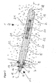
- Fig. 1 shows in a clear representation of a pressure tube anchor 1 according to the invention, which is arranged within a borehole 2.
- the Ankerzugglied 3 of the pressure tube anchor 1 consists of a single element in the form of a ribbed steel rod, the ribs form a thread and the longitudinal axis carries the reference numeral 4. Except for the end portions of the Ankerzugglied 3 is surrounded by a cladding tube 5, within which it is guided longitudinally displaceable without adhesion.
- the armature link member 3 encloses a cuff-like supporting element 9, which is supported with a lower annular flange on the abutment plate 6 and with an upper annular flange an anchor plate 10 carries, in which the pressure tube anchor 1 is held with its anchor head 11.
- the anchor plate 10 has a likewise central opening 12, the spherical surface of which is the air side expands. At the lower edge of the opening 12 includes a transverse to the anchor plate 10 extending pipe socket 13, which forms a connection to the upper end of the cladding tube 5 with its free end.
- an anchor nut 14 is screwed onto the air-side end of the Ankerzugglieds 3, which has a corresponding to the shape of the soffit surface of the opening 12 spherical peripheral portion and is supported with this on the anchor plate 10.
- the complementary design of anchor nut 14 and anchor plate 10 allows an angle compensation, if the anchor plate 10 is not perpendicular to the longitudinal axis 4 of the pressure tube anchor 1.
- a bell-shaped cap 15 is further pushed onto the Ankerzugglied 3, which surrounds the armature nut 14 and closes tightly to the anchor plate 10 back.
- the cap 15 is fixed by means of a further, screwed onto the end of the Ankerzugglieds 3 nut 16th
- the anchor foot construction comprises a sleeve-like anchor foot 19 whose internal thread is in engagement with the ribs of the Ankerzugglieds 3. In this way, a tensile and pressure resistant, but at the same time releasable connection between the Ankerzugglied 3 and anchor foot 19 comes about.
- Each pressure tube 20 is provided at its outer periphery with spacers 21 which center the pressure tube anchor 1 in the borehole 2.
- the cavity between the wall of the borehole 2 and the pressure tube anchor 1 is pressed with a curable injection material 22.
- the hardened injection material 22 thus forms within the bore hole 2 a Verpressenia which causes a toothing mainly between the pressure pipes 20 and the wall of the borehole 2, so that the originating from the Ankerzugglied 3, axially acting on the pressure pipes 20 forces on the grout in Substrate 7 can be delivered.
- the exact structure of the pressure pipes 20 goes out of the Fig. 2 to 5 out.
- the pressure pipes 20 each consist of a circular-cylindrical one-piece body, made of a material with a low elongation at break, for example made of cast steel, glass, concrete, ceramic and the like.
- Along side generatrices extends a first pair of longitudinal grooves 23, which lie diametrically opposite relative to the longitudinal axis 4.
- the longitudinal grooves 23 In cross-section, the longitudinal grooves 23 each have a continuous course, ie have neither corners nor edges.
- the sides 24 are inclined symmetrically to each other, so that the groove cross-section to the rounded groove bottom 25 becomes narrower.
- the longitudinal grooves 23 extend from the outer circumference to about 75% of the wall thickness of the pressure tube 20, so that webs 30 remain there as a residual cross section.
- a second pair of longitudinal grooves 26, which also extend in a diametrical position axially parallel to the longitudinal axis 4 along the inner wall of the pressure tube 20.
- the longitudinal grooves 26 also have a continuous course with in the direction of the rounded base 27 converging sides 28.
- the radial depth of the longitudinal grooves 26 is also about 75% of the wall thickness of the pressure tube 20, so that there webs 30 are formed. Otherwise, a plurality of circumferential ribs 29, whose function is to produce a secure bond to the injection material 22, are distributed over the outer circumference.
- predetermined breaking points are within the scope of the invention.
- areas of reduced pipe wall thickness may additionally have a perforation and / or consist of a material of lesser strength.
- pressure pipes are within the scope of the invention, the predetermined breaking points are formed only by perforations and / or areas with a material of lesser strength.
Landscapes
- Engineering & Computer Science (AREA)
- Structural Engineering (AREA)
- Life Sciences & Earth Sciences (AREA)
- General Life Sciences & Earth Sciences (AREA)
- Mining & Mineral Resources (AREA)
- Paleontology (AREA)
- Civil Engineering (AREA)
- General Engineering & Computer Science (AREA)
- Piles And Underground Anchors (AREA)
Applications Claiming Priority (1)
| Application Number | Priority Date | Filing Date | Title |
|---|---|---|---|
| DE201020004381 DE202010004381U1 (de) | 2010-03-30 | 2010-03-30 | Druckrohr sowie daraus hergestellter Erdanker |
Publications (3)
| Publication Number | Publication Date |
|---|---|
| EP2372026A2 true EP2372026A2 (fr) | 2011-10-05 |
| EP2372026A3 EP2372026A3 (fr) | 2014-07-02 |
| EP2372026B1 EP2372026B1 (fr) | 2015-11-11 |
Family
ID=42558367
Family Applications (1)
| Application Number | Title | Priority Date | Filing Date |
|---|---|---|---|
| EP10009682.5A Active EP2372026B1 (fr) | 2010-03-30 | 2010-09-16 | Cable de tension et ancrage au sol fabriqué à l'aide de celui-ci |
Country Status (3)
| Country | Link |
|---|---|
| EP (1) | EP2372026B1 (fr) |
| DE (1) | DE202010004381U1 (fr) |
| ES (1) | ES2561049T3 (fr) |
Families Citing this family (5)
| Publication number | Priority date | Publication date | Assignee | Title |
|---|---|---|---|---|
| CN105544550A (zh) * | 2016-02-07 | 2016-05-04 | 北京市勘察设计研究院有限公司 | 一种通过利用气囊封堵装置的反重力加压注浆方法 |
| NL2018677B1 (en) | 2017-04-10 | 2018-10-19 | Univ Delft Tech | Injected bolted connection |
| CN112576291A (zh) * | 2020-12-29 | 2021-03-30 | 中国地质调查局武汉地质调查中心(中南地质科技创新中心) | 一种玄武岩纤维筋的锚索及其监测系统 |
| DE102023117011A1 (de) * | 2023-06-28 | 2025-01-02 | Karlsruher Institut für Technologie, Körperschaft des öffentlichen Rechts | Geotechnischer Anker mit Quellkörper, Ankersystem und Herstellung des Ankersystems |
| WO2026041236A1 (fr) * | 2024-08-23 | 2026-02-26 | Dywidag-Systems International Gmbh | Ancre de base |
Citations (3)
| Publication number | Priority date | Publication date | Assignee | Title |
|---|---|---|---|---|
| DE2353652A1 (de) | 1973-10-26 | 1975-05-07 | Bauer Karl Kg | Ausbaubarer verpressanker mit zerstoerbarem ankerfuss |
| EP0545471A1 (fr) | 1991-11-29 | 1993-06-09 | Hollandsche Beton Groep N.V. | Procédé pour fixer une ancre pour l'ancrage de murs de soutènement, de bâtiment, de rideaux, de palplanches, de murs de quais et similaires |
| EP1486617A1 (fr) | 2000-05-08 | 2004-12-15 | Dywidag-Systems International GmbH | Ancrage injecté récupérable |
-
2010
- 2010-03-30 DE DE201020004381 patent/DE202010004381U1/de not_active Expired - Lifetime
- 2010-09-16 ES ES10009682.5T patent/ES2561049T3/es active Active
- 2010-09-16 EP EP10009682.5A patent/EP2372026B1/fr active Active
Patent Citations (3)
| Publication number | Priority date | Publication date | Assignee | Title |
|---|---|---|---|---|
| DE2353652A1 (de) | 1973-10-26 | 1975-05-07 | Bauer Karl Kg | Ausbaubarer verpressanker mit zerstoerbarem ankerfuss |
| EP0545471A1 (fr) | 1991-11-29 | 1993-06-09 | Hollandsche Beton Groep N.V. | Procédé pour fixer une ancre pour l'ancrage de murs de soutènement, de bâtiment, de rideaux, de palplanches, de murs de quais et similaires |
| EP1486617A1 (fr) | 2000-05-08 | 2004-12-15 | Dywidag-Systems International GmbH | Ancrage injecté récupérable |
Also Published As
| Publication number | Publication date |
|---|---|
| EP2372026A3 (fr) | 2014-07-02 |
| DE202010004381U1 (de) | 2010-08-12 |
| EP2372026B1 (fr) | 2015-11-11 |
| ES2561049T3 (es) | 2016-02-24 |
Similar Documents
| Publication | Publication Date | Title |
|---|---|---|
| EP2087203B1 (fr) | Ancrage coulissant amélioré | |
| DE202008001248U1 (de) | Erd- oder Felsanker mit einem Ankerzugglied aus einem oder mehreren Einzelelementen mit korrosionsgeschützter Ankerkopfausbildung | |
| EP2257690A1 (fr) | Cheville autoforeuse protégée contre la corrosion, et bloc d'éléments de cheville, et leur procédé de fabrication | |
| EP1381756B2 (fr) | Procede et dispositif de forage d'un trou et de fixation d'un ancrage dans un trou de forage | |
| EP1905923A2 (fr) | Tige d'ancrage et dispositif destiné au renforcement de composants existants contre le cisaillement à l'aide d'une telle tige d'ancrage | |
| EP2372026B1 (fr) | Cable de tension et ancrage au sol fabriqué à l'aide de celui-ci | |
| EP1397601B1 (fr) | Tige d'ancrage | |
| EP2365154B1 (fr) | Dispositif d'ancrage d'articulations de traction | |
| EP1888878B1 (fr) | Procede et dispositif pour le forage, notamment pour le forage par percussion ou par roto-percussion, d'un trou dans le sol ou la roche | |
| DE3320460C1 (de) | Nachgiebiger Gebirgsanker | |
| DE19800581A1 (de) | Spreizelement mit verschiedenen Spreizzonen | |
| DE19513202A1 (de) | Vorrichtung zur Verankerung von Bewehrungs- bzw. Spannstählen in Verankerungsgründen | |
| EP2247827B1 (fr) | Ancrage coulissant amélioré | |
| EP2893139B1 (fr) | Ensemble d'ancrage haute résistance d'un élément de précontrainte dans une pièce, l'élément de précontrainte comportant une tige de précontrainte, et procédé de production dudit ancrage | |
| EP3094787A1 (fr) | Dispositif d'ancrage au sol | |
| EP1154077B1 (fr) | Ancrage injecté récupérable | |
| EP0739442B1 (fr) | Dispositif d'ancrage dans la roche, en plastique arme fibres de verre, pouvant etre tendu | |
| DE19626828C2 (de) | Verfahren zur Erstellung eines rückbaubaren Verpreßankers mit einem Verpreßkörper und einem oder mehreren angeschlossenen Zuggliedern | |
| DE69408570T2 (de) | Mittel zum verankern von felsankern, hergestellt aus stahlbeton, in einem bohrloch. | |
| DE2201950C3 (de) | Verpreßanker zum Verankern von Bauteilen in erdigem oder felsigem Baugrund | |
| DE2353652A1 (de) | Ausbaubarer verpressanker mit zerstoerbarem ankerfuss | |
| EP0899382A1 (fr) | Elément d'ancrage d'un tirant ancrage | |
| DE10360156A1 (de) | Dübel | |
| WO2006048110A1 (fr) | Systeme d'ancrage et utilisation d'un tirant | |
| DE29707501U1 (de) | Schraub-Injektionsanker |
Legal Events
| Date | Code | Title | Description |
|---|---|---|---|
| PUAI | Public reference made under article 153(3) epc to a published international application that has entered the european phase |
Free format text: ORIGINAL CODE: 0009012 |
|
| AK | Designated contracting states |
Kind code of ref document: A2 Designated state(s): AL AT BE BG CH CY CZ DE DK EE ES FI FR GB GR HR HU IE IS IT LI LT LU LV MC MK MT NL NO PL PT RO SE SI SK SM TR |
|
| AX | Request for extension of the european patent |
Extension state: BA ME RS |
|
| PUAL | Search report despatched |
Free format text: ORIGINAL CODE: 0009013 |
|
| AK | Designated contracting states |
Kind code of ref document: A3 Designated state(s): AL AT BE BG CH CY CZ DE DK EE ES FI FR GB GR HR HU IE IS IT LI LT LU LV MC MK MT NL NO PL PT RO SE SI SK SM TR |
|
| AX | Request for extension of the european patent |
Extension state: BA ME RS |
|
| RIC1 | Information provided on ipc code assigned before grant |
Ipc: E02D 5/80 20060101ALI20140528BHEP Ipc: E02D 5/76 20060101AFI20140528BHEP |
|
| 17P | Request for examination filed |
Effective date: 20140617 |
|
| RBV | Designated contracting states (corrected) |
Designated state(s): AL AT BE BG CH CY CZ DE DK EE ES FI FR GB GR HR HU IE IS IT LI LT LU LV MC MK MT NL NO PL PT RO SE SI SK SM TR |
|
| RIC1 | Information provided on ipc code assigned before grant |
Ipc: E02D 5/76 20060101AFI20141128BHEP Ipc: E02D 5/80 20060101ALI20141128BHEP |
|
| GRAP | Despatch of communication of intention to grant a patent |
Free format text: ORIGINAL CODE: EPIDOSNIGR1 |
|
| INTG | Intention to grant announced |
Effective date: 20150528 |
|
| GRAS | Grant fee paid |
Free format text: ORIGINAL CODE: EPIDOSNIGR3 |
|
| GRAA | (expected) grant |
Free format text: ORIGINAL CODE: 0009210 |
|
| AK | Designated contracting states |
Kind code of ref document: B1 Designated state(s): AL AT BE BG CH CY CZ DE DK EE ES FI FR GB GR HR HU IE IS IT LI LT LU LV MC MK MT NL NO PL PT RO SE SI SK SM TR |
|
| REG | Reference to a national code |
Ref country code: GB Ref legal event code: FG4D Free format text: NOT ENGLISH |
|
| REG | Reference to a national code |
Ref country code: CH Ref legal event code: EP |
|
| REG | Reference to a national code |
Ref country code: IE Ref legal event code: FG4D Free format text: LANGUAGE OF EP DOCUMENT: GERMAN |
|
| REG | Reference to a national code |
Ref country code: AT Ref legal event code: REF Ref document number: 760537 Country of ref document: AT Kind code of ref document: T Effective date: 20151215 |
|
| REG | Reference to a national code |
Ref country code: DE Ref legal event code: R096 Ref document number: 502010010615 Country of ref document: DE |
|
| REG | Reference to a national code |
Ref country code: CH Ref legal event code: NV Representative=s name: PATENTANWAELTE SCHAAD, BALASS, MENZL AND PARTN, CH |
|
| REG | Reference to a national code |
Ref country code: ES Ref legal event code: FG2A Ref document number: 2561049 Country of ref document: ES Kind code of ref document: T3 Effective date: 20160224 |
|
| REG | Reference to a national code |
Ref country code: NL Ref legal event code: FP |
|
| REG | Reference to a national code |
Ref country code: LT Ref legal event code: MG4D |
|
| PG25 | Lapsed in a contracting state [announced via postgrant information from national office to epo] |
Ref country code: LT Free format text: LAPSE BECAUSE OF FAILURE TO SUBMIT A TRANSLATION OF THE DESCRIPTION OR TO PAY THE FEE WITHIN THE PRESCRIBED TIME-LIMIT Effective date: 20151111 Ref country code: IS Free format text: LAPSE BECAUSE OF FAILURE TO SUBMIT A TRANSLATION OF THE DESCRIPTION OR TO PAY THE FEE WITHIN THE PRESCRIBED TIME-LIMIT Effective date: 20160311 Ref country code: NO Free format text: LAPSE BECAUSE OF FAILURE TO SUBMIT A TRANSLATION OF THE DESCRIPTION OR TO PAY THE FEE WITHIN THE PRESCRIBED TIME-LIMIT Effective date: 20160211 Ref country code: HR Free format text: LAPSE BECAUSE OF FAILURE TO SUBMIT A TRANSLATION OF THE DESCRIPTION OR TO PAY THE FEE WITHIN THE PRESCRIBED TIME-LIMIT Effective date: 20151111 |
|
| PG25 | Lapsed in a contracting state [announced via postgrant information from national office to epo] |
Ref country code: LV Free format text: LAPSE BECAUSE OF FAILURE TO SUBMIT A TRANSLATION OF THE DESCRIPTION OR TO PAY THE FEE WITHIN THE PRESCRIBED TIME-LIMIT Effective date: 20151111 Ref country code: PL Free format text: LAPSE BECAUSE OF FAILURE TO SUBMIT A TRANSLATION OF THE DESCRIPTION OR TO PAY THE FEE WITHIN THE PRESCRIBED TIME-LIMIT Effective date: 20151111 Ref country code: FI Free format text: LAPSE BECAUSE OF FAILURE TO SUBMIT A TRANSLATION OF THE DESCRIPTION OR TO PAY THE FEE WITHIN THE PRESCRIBED TIME-LIMIT Effective date: 20151111 Ref country code: GR Free format text: LAPSE BECAUSE OF FAILURE TO SUBMIT A TRANSLATION OF THE DESCRIPTION OR TO PAY THE FEE WITHIN THE PRESCRIBED TIME-LIMIT Effective date: 20160212 Ref country code: SE Free format text: LAPSE BECAUSE OF FAILURE TO SUBMIT A TRANSLATION OF THE DESCRIPTION OR TO PAY THE FEE WITHIN THE PRESCRIBED TIME-LIMIT Effective date: 20151111 Ref country code: PT Free format text: LAPSE BECAUSE OF FAILURE TO SUBMIT A TRANSLATION OF THE DESCRIPTION OR TO PAY THE FEE WITHIN THE PRESCRIBED TIME-LIMIT Effective date: 20160311 |
|
| PG25 | Lapsed in a contracting state [announced via postgrant information from national office to epo] |
Ref country code: CZ Free format text: LAPSE BECAUSE OF FAILURE TO SUBMIT A TRANSLATION OF THE DESCRIPTION OR TO PAY THE FEE WITHIN THE PRESCRIBED TIME-LIMIT Effective date: 20151111 |
|
| REG | Reference to a national code |
Ref country code: DE Ref legal event code: R097 Ref document number: 502010010615 Country of ref document: DE |
|
| PG25 | Lapsed in a contracting state [announced via postgrant information from national office to epo] |
Ref country code: SK Free format text: LAPSE BECAUSE OF FAILURE TO SUBMIT A TRANSLATION OF THE DESCRIPTION OR TO PAY THE FEE WITHIN THE PRESCRIBED TIME-LIMIT Effective date: 20151111 Ref country code: SM Free format text: LAPSE BECAUSE OF FAILURE TO SUBMIT A TRANSLATION OF THE DESCRIPTION OR TO PAY THE FEE WITHIN THE PRESCRIBED TIME-LIMIT Effective date: 20151111 Ref country code: DK Free format text: LAPSE BECAUSE OF FAILURE TO SUBMIT A TRANSLATION OF THE DESCRIPTION OR TO PAY THE FEE WITHIN THE PRESCRIBED TIME-LIMIT Effective date: 20151111 Ref country code: EE Free format text: LAPSE BECAUSE OF FAILURE TO SUBMIT A TRANSLATION OF THE DESCRIPTION OR TO PAY THE FEE WITHIN THE PRESCRIBED TIME-LIMIT Effective date: 20151111 Ref country code: RO Free format text: LAPSE BECAUSE OF FAILURE TO SUBMIT A TRANSLATION OF THE DESCRIPTION OR TO PAY THE FEE WITHIN THE PRESCRIBED TIME-LIMIT Effective date: 20151111 |
|
| PLBE | No opposition filed within time limit |
Free format text: ORIGINAL CODE: 0009261 |
|
| STAA | Information on the status of an ep patent application or granted ep patent |
Free format text: STATUS: NO OPPOSITION FILED WITHIN TIME LIMIT |
|
| REG | Reference to a national code |
Ref country code: FR Ref legal event code: PLFP Year of fee payment: 7 |
|
| 26N | No opposition filed |
Effective date: 20160812 |
|
| PG25 | Lapsed in a contracting state [announced via postgrant information from national office to epo] |
Ref country code: SI Free format text: LAPSE BECAUSE OF FAILURE TO SUBMIT A TRANSLATION OF THE DESCRIPTION OR TO PAY THE FEE WITHIN THE PRESCRIBED TIME-LIMIT Effective date: 20151111 |
|
| PG25 | Lapsed in a contracting state [announced via postgrant information from national office to epo] |
Ref country code: MC Free format text: LAPSE BECAUSE OF FAILURE TO SUBMIT A TRANSLATION OF THE DESCRIPTION OR TO PAY THE FEE WITHIN THE PRESCRIBED TIME-LIMIT Effective date: 20151111 |
|
| REG | Reference to a national code |
Ref country code: IE Ref legal event code: MM4A |
|
| PG25 | Lapsed in a contracting state [announced via postgrant information from national office to epo] |
Ref country code: IE Free format text: LAPSE BECAUSE OF NON-PAYMENT OF DUE FEES Effective date: 20160916 |
|
| PG25 | Lapsed in a contracting state [announced via postgrant information from national office to epo] |
Ref country code: LU Free format text: LAPSE BECAUSE OF NON-PAYMENT OF DUE FEES Effective date: 20160916 |
|
| REG | Reference to a national code |
Ref country code: FR Ref legal event code: PLFP Year of fee payment: 8 |
|
| PG25 | Lapsed in a contracting state [announced via postgrant information from national office to epo] |
Ref country code: CY Free format text: LAPSE BECAUSE OF FAILURE TO SUBMIT A TRANSLATION OF THE DESCRIPTION OR TO PAY THE FEE WITHIN THE PRESCRIBED TIME-LIMIT Effective date: 20151111 Ref country code: HU Free format text: LAPSE BECAUSE OF FAILURE TO SUBMIT A TRANSLATION OF THE DESCRIPTION OR TO PAY THE FEE WITHIN THE PRESCRIBED TIME-LIMIT; INVALID AB INITIO Effective date: 20100916 |
|
| PG25 | Lapsed in a contracting state [announced via postgrant information from national office to epo] |
Ref country code: TR Free format text: LAPSE BECAUSE OF FAILURE TO SUBMIT A TRANSLATION OF THE DESCRIPTION OR TO PAY THE FEE WITHIN THE PRESCRIBED TIME-LIMIT Effective date: 20151111 Ref country code: MK Free format text: LAPSE BECAUSE OF FAILURE TO SUBMIT A TRANSLATION OF THE DESCRIPTION OR TO PAY THE FEE WITHIN THE PRESCRIBED TIME-LIMIT Effective date: 20151111 Ref country code: MT Free format text: LAPSE BECAUSE OF FAILURE TO SUBMIT A TRANSLATION OF THE DESCRIPTION OR TO PAY THE FEE WITHIN THE PRESCRIBED TIME-LIMIT Effective date: 20151111 |
|
| PG25 | Lapsed in a contracting state [announced via postgrant information from national office to epo] |
Ref country code: BG Free format text: LAPSE BECAUSE OF FAILURE TO SUBMIT A TRANSLATION OF THE DESCRIPTION OR TO PAY THE FEE WITHIN THE PRESCRIBED TIME-LIMIT Effective date: 20151111 |
|
| REG | Reference to a national code |
Ref country code: FR Ref legal event code: PLFP Year of fee payment: 9 |
|
| PG25 | Lapsed in a contracting state [announced via postgrant information from national office to epo] |
Ref country code: AL Free format text: LAPSE BECAUSE OF FAILURE TO SUBMIT A TRANSLATION OF THE DESCRIPTION OR TO PAY THE FEE WITHIN THE PRESCRIBED TIME-LIMIT Effective date: 20151111 |
|
| P01 | Opt-out of the competence of the unified patent court (upc) registered |
Effective date: 20230512 |
|
| REG | Reference to a national code |
Ref country code: CH Ref legal event code: U11 Free format text: ST27 STATUS EVENT CODE: U-0-0-U10-U11 (AS PROVIDED BY THE NATIONAL OFFICE) Effective date: 20251001 |
|
| PGFP | Annual fee paid to national office [announced via postgrant information from national office to epo] |
Ref country code: DE Payment date: 20250929 Year of fee payment: 16 |
|
| PGFP | Annual fee paid to national office [announced via postgrant information from national office to epo] |
Ref country code: NL Payment date: 20250926 Year of fee payment: 16 Ref country code: IT Payment date: 20250919 Year of fee payment: 16 |
|
| PGFP | Annual fee paid to national office [announced via postgrant information from national office to epo] |
Ref country code: BE Payment date: 20250929 Year of fee payment: 16 Ref country code: GB Payment date: 20250929 Year of fee payment: 16 |
|
| PGFP | Annual fee paid to national office [announced via postgrant information from national office to epo] |
Ref country code: AT Payment date: 20250929 Year of fee payment: 16 Ref country code: FR Payment date: 20250925 Year of fee payment: 16 |
|
| PGFP | Annual fee paid to national office [announced via postgrant information from national office to epo] |
Ref country code: CH Payment date: 20251001 Year of fee payment: 16 |
|
| PGFP | Annual fee paid to national office [announced via postgrant information from national office to epo] |
Ref country code: ES Payment date: 20251001 Year of fee payment: 16 |