EP2372051A2 - Ensemble de poignée - Google Patents
Ensemble de poignée Download PDFInfo
- Publication number
- EP2372051A2 EP2372051A2 EP11000627A EP11000627A EP2372051A2 EP 2372051 A2 EP2372051 A2 EP 2372051A2 EP 11000627 A EP11000627 A EP 11000627A EP 11000627 A EP11000627 A EP 11000627A EP 2372051 A2 EP2372051 A2 EP 2372051A2
- Authority
- EP
- European Patent Office
- Prior art keywords
- handle
- substructure
- square pin
- pin
- square
- Prior art date
- Legal status (The legal status is an assumption and is not a legal conclusion. Google has not performed a legal analysis and makes no representation as to the accuracy of the status listed.)
- Withdrawn
Links
- 238000000034 method Methods 0.000 claims abstract description 5
- 230000015572 biosynthetic process Effects 0.000 description 3
- 230000000712 assembly Effects 0.000 description 2
- 238000000429 assembly Methods 0.000 description 2
- 238000004519 manufacturing process Methods 0.000 description 2
- 238000004873 anchoring Methods 0.000 description 1
- 230000005540 biological transmission Effects 0.000 description 1
- 230000001419 dependent effect Effects 0.000 description 1
Images


Classifications
-
- E—FIXED CONSTRUCTIONS
- E05—LOCKS; KEYS; WINDOW OR DOOR FITTINGS; SAFES
- E05B—LOCKS; ACCESSORIES THEREFOR; HANDCUFFS
- E05B3/00—Fastening knobs or handles to lock or latch parts
- E05B3/02—Fastening knobs or handles to the spindle by pinning or riveting
-
- E—FIXED CONSTRUCTIONS
- E05—LOCKS; KEYS; WINDOW OR DOOR FITTINGS; SAFES
- E05B—LOCKS; ACCESSORIES THEREFOR; HANDCUFFS
- E05B3/00—Fastening knobs or handles to lock or latch parts
- E05B3/06—Fastening knobs or handles to lock or latch parts by means arranged in or on the rose or escutcheon
-
- E—FIXED CONSTRUCTIONS
- E05—LOCKS; KEYS; WINDOW OR DOOR FITTINGS; SAFES
- E05B—LOCKS; ACCESSORIES THEREFOR; HANDCUFFS
- E05B15/00—Other details of locks; Parts for engagement by bolts of fastening devices
- E05B15/0033—Spindles for handles, e.g. square spindles
Definitions
- the latter variant has the disadvantage that the screw head remains visible from the outside, which may be undesirable for aesthetic reasons, while the spring bolt variant ultimately allows no play connection between square pin and handle, so that the handle assembly not only leaves an unstable impression, but also there is a risk that the handle will come loose after frequent use of the handle assembly of the square pin.
- the invention has for its object to provide a more stable handle assembly, which is also produced with less economic effort.
- a handle assembly having the features of claim 1 and in particular by the fact that the square pin is fixed by means of a pin connection to the handle.
- the handle and the square pin pierces at a suitable location transverse to the longitudinal extent of the square pin and a suitable dowel pin or a suitable clamping sleeve to be inserted into the hole.
- a positive connection between the square pin and the handle is achieved by which game is effectively canceled between these two components and which is essentially insoluble in normal use of the handle assembly.
- the square pin and the handle can thus easily and reliably connect play reliably and permanently, which ultimately leads to increased stability of the handle assembly.
- Pinning the square pin to the handle also allows the square pin to protrude from the handle with a desired length so that a type of square pin can be used in different types of handle assemblies. This simplifies the storage, as not a separate type of square pin must be kept for each type of handle assembly, and ultimately contributes to a more economical production of the handle assembly.
- a clamping pin or a clamping sleeve of the pin connection extends transversely to the longitudinal extent of the square pin through the square pin and a shoulder of the handle.
- the square pin is fixable by means of a screw connection to the substructure.
- the screw allows a backlash-free and permanently reliable mounting of the handle on the substructure and also ensures optimal transmission of tensile forces from the handle to the substructure upon actuation of the handle assembly.
- the formation of the external thread on the square pin and thereby made possible screw with the substructure also has the advantage that seen with a correspondingly long formation of the external thread in the longitudinal direction of the square pin significant tolerances in the length of protruding from the handle portion of the square pin can be compensated. Even if the square pin protrudes different distances from the handle for different applications, the handle can still be securely attached to the on the substructure
- the substructure has a wall with a passage opening through which the square pin can extend, so that it can be fixed to the substructure by a threaded nut screwed onto the external thread from the rear side of the substructure facing away from the grip piece.
- the cross section of the passage opening is adapted to the cross section of the square pin.
- the wall can be rotatably mounted in the substructure.
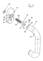
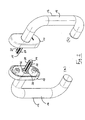
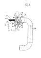
- the handle assembly shown in the figures comprises a mountable to a window or a door substructure 10, a handle 12 and a square pin 14 for connecting the handle 12 with the substructure 10th
- the handle 12 has a handle portion 16 which is angled several times and has a constant circular outer cross-section over substantially its entire length.
- the grip part 16 can also have any other shape which is suitable for a window or door handle.
- a projection 18 protrudes from the handle portion 16, which also has a substantially circular outer cross-section, but has a relation to the handle portion 16 reduced outer diameter.
- a blind bore 20 extends from an end face of the projection 18 into the handle part 16 into which the square pin 14 can be inserted.
- the square pin 14 has a first portion 22, in the longitudinal direction of the square pin 14 seen a second section 24 connects.
- the side surfaces 26 of the square pin 14 are formed substantially completely flat, so that the square pin 14 here has a typical square pins relatively sharp-edged, in particular square, cross-section.
- the square pin 14 is provided with an external thread 28, which is cut especially in the edges, adjacent to which adjacent side surfaces 26.
- a hole 30 is drilled in the region of the projection 18, which extends transversely to the longitudinal extent of the square pin 14 through the projection 18 and the square pin 14 received therein.
- a clamping pin 32 or a clamping sleeve is used, which provides by positive engagement for an at least approximately free of play anchoring of the square pin 14 in the handle 12.
- a hollow cylindrical receptacle 36 is provided for receiving the projection 18, whose inner diameter and depth are adapted to the dimensions of the projection 18.
- the receptacle 36 is bounded by a wall 38, in which a passage 40 is provided, whose cross section is adapted to the cross section of the square pin 14.
- the handle 12 provided with the square pin 14 is placed on the substructure 18 so that the square pin 14 extends through the passage 40 in the wall 38 and the projection 18 of the handle 12 in the receptacle 36th the substructure 10 is completely absorbed.
- a threaded nut 42 is now screwed from the handle 12 remote from the rear side of the substructure 10 forth on the external thread 28 of extending through the wall 38 through square pin 14, and indeed so far until the threaded nut 42nd to the rear of the wall 38 abuts and the handle 12 is connected to the substructure 10 without play.
- the receptacle 36 is rotatably mounted in the substructure 10 about the longitudinal axis of the square pin 14 around pivoting of the handle 12 connected to the substructure 10 about the longitudinal axis of the square pin 14 and thereby actuation of a closing mechanism associated with the handle assembly of the window or the door enable.
Landscapes
- Engineering & Computer Science (AREA)
- Mechanical Engineering (AREA)
- Lock And Its Accessories (AREA)
- Securing Of Glass Panes Or The Like (AREA)
- Window Of Vehicle (AREA)
Applications Claiming Priority (1)
| Application Number | Priority Date | Filing Date | Title |
|---|---|---|---|
| DE201010013529 DE102010013529A1 (de) | 2010-03-31 | 2010-03-31 | Griffanordnung |
Publications (2)
| Publication Number | Publication Date |
|---|---|
| EP2372051A2 true EP2372051A2 (fr) | 2011-10-05 |
| EP2372051A3 EP2372051A3 (fr) | 2013-07-24 |
Family
ID=44275610
Family Applications (1)
| Application Number | Title | Priority Date | Filing Date |
|---|---|---|---|
| EP11000627.7A Withdrawn EP2372051A3 (fr) | 2010-03-31 | 2011-01-26 | Ensemble de poignée |
Country Status (2)
| Country | Link |
|---|---|
| EP (1) | EP2372051A3 (fr) |
| DE (1) | DE102010013529A1 (fr) |
Families Citing this family (2)
| Publication number | Priority date | Publication date | Assignee | Title |
|---|---|---|---|---|
| CN105781234A (zh) * | 2016-04-28 | 2016-07-20 | 王林军 | 一种弹子插芯门锁的执手安装组件 |
| CN110219524A (zh) * | 2019-06-28 | 2019-09-10 | 太仓德纳森机电工程有限公司 | 一种电气控制柜柜门锁 |
Family Cites Families (10)
| Publication number | Priority date | Publication date | Assignee | Title |
|---|---|---|---|---|
| DE290671C (fr) * | ||||
| US945165A (en) * | 1909-09-02 | 1910-01-04 | P & F Corbin | Knob attachment. |
| FR820630A (fr) * | 1937-04-15 | 1937-11-16 | Bouton de porte | |
| FR1429919A (fr) * | 1965-04-05 | 1966-02-25 | Ensemble bec de cane-plaque de propreté réglable | |
| DE2727922A1 (de) * | 1977-06-21 | 1979-01-04 | Grossteinbeck Gmbh Otto | Tuerdrueckerverbindung |
| DE2806417C2 (de) * | 1978-02-15 | 1986-03-20 | Heinrich Wilke Gmbh, 3548 Arolsen | Mehrkant-Schloßstift |
| DE8209457U1 (de) * | 1982-04-02 | 1982-07-08 | Decker, Karl, 2400 Lübeck | Tuerdruecker-garnitur mit holzdrueckern |
| FR2710094B1 (fr) * | 1993-09-15 | 1995-12-01 | Chrisligne | Système de fixation d'un bouton sur une face d'un panneau de porte, notamment une porte palière. |
| DE102005001446A1 (de) * | 2005-01-12 | 2006-07-20 | Hewi Heinrich Wilke Gmbh | Vierkantstift |
| DE202005017497U1 (de) * | 2005-11-07 | 2007-03-15 | Hoppe Ag | Betätigungshandhabe |
-
2010
- 2010-03-31 DE DE201010013529 patent/DE102010013529A1/de not_active Withdrawn
-
2011
- 2011-01-26 EP EP11000627.7A patent/EP2372051A3/fr not_active Withdrawn
Non-Patent Citations (1)
| Title |
|---|
| None |
Also Published As
| Publication number | Publication date |
|---|---|
| EP2372051A3 (fr) | 2013-07-24 |
| DE102010013529A1 (de) | 2011-10-06 |
Similar Documents
| Publication | Publication Date | Title |
|---|---|---|
| DE10229300B3 (de) | Verbindungssystem für Bauteile, insbesondere für Möbelteile | |
| EP2742199B1 (fr) | Système de fixation pour fixer une pièce sur une rainure d'une fenêtre, d'une porte ou analogue | |
| DE3523155C2 (fr) | ||
| EP2366851A2 (fr) | Agencement de rosaces pour une porte | |
| EP1072745B1 (fr) | Ferrure de verrouillage pour fenêtres ou portes | |
| EP2742826A1 (fr) | Dispositif de fixation pour fixer un élément, par exemple une tringle à un second élément, ainsi que fixation de tringle pour tiroir et tiroir avec une fixation de tringle | |
| DE4210488A1 (de) | Verbindungseinrichtung für ein insbesondere rohrförmiges Bauteil | |
| DE8903833U1 (de) | Distanzschraube | |
| EP2372051A2 (fr) | Ensemble de poignée | |
| EP2913465B1 (fr) | Dispositif de charniere pour portes, fenetres ou similaires | |
| EP0592854B1 (fr) | Dispositif de montage d'une poignée de porte amovible | |
| EP2172606A2 (fr) | Dispositif de poignée | |
| DE3835835A1 (de) | Fenster, tuer od. dgl., bei dem bzw. der zumindest der fluegelrahmen aus metall- oder kunststoffprofilen zusammengesetzt ist | |
| DE3147092C2 (de) | Verbindungssystem mit wenigstens einem Eckbogenelement | |
| EP3406916B1 (fr) | Équerre pour profilés de support | |
| DE4339042C1 (de) | Vorrichtung zur Befestigung eines Bauteils an einem Verbindungsstift | |
| DE3725719C2 (de) | Verfahren und Vorrichtung zur Befestigung eines Griffes, oder dergleichen | |
| EP1114905A1 (fr) | Douille de montage | |
| EP4151866B1 (fr) | Dispositif de fixation | |
| DE20106561U1 (de) | Vorrichtung zum Verbinden von Profilstäben | |
| DE102008011334A1 (de) | Griffbefestigung | |
| EP0235385A2 (fr) | Jonction de poignée de porte | |
| DE2419462B2 (fr) | ||
| DE29712974U1 (de) | Vorrichtung zur Befestigung eines Türgriffs an einem Türrahmen aus Holz | |
| DE20219174U1 (de) | Dichtung insbesondere selbsttätig absenkende Bodendichtung für Türen |
Legal Events
| Date | Code | Title | Description |
|---|---|---|---|
| PUAI | Public reference made under article 153(3) epc to a published international application that has entered the european phase |
Free format text: ORIGINAL CODE: 0009012 |
|
| AK | Designated contracting states |
Kind code of ref document: A2 Designated state(s): AL AT BE BG CH CY CZ DE DK EE ES FI FR GB GR HR HU IE IS IT LI LT LU LV MC MK MT NL NO PL PT RO RS SE SI SK SM TR |
|
| AX | Request for extension of the european patent |
Extension state: BA ME |
|
| PUAL | Search report despatched |
Free format text: ORIGINAL CODE: 0009013 |
|
| AK | Designated contracting states |
Kind code of ref document: A3 Designated state(s): AL AT BE BG CH CY CZ DE DK EE ES FI FR GB GR HR HU IE IS IT LI LT LU LV MC MK MT NL NO PL PT RO RS SE SI SK SM TR |
|
| AX | Request for extension of the european patent |
Extension state: BA ME |
|
| RIC1 | Information provided on ipc code assigned before grant |
Ipc: E05B 3/08 20060101ALI20130614BHEP Ipc: E05B 3/02 20060101ALI20130614BHEP Ipc: E05B 1/00 20060101AFI20130614BHEP |
|
| 17P | Request for examination filed |
Effective date: 20131209 |
|
| RBV | Designated contracting states (corrected) |
Designated state(s): AL AT BE BG CH CY CZ DE DK EE ES FI FR GB GR HR HU IE IS IT LI LT LU LV MC MK MT NL NO PL PT RO RS SE SI SK SM TR |
|
| 17Q | First examination report despatched |
Effective date: 20140513 |
|
| STAA | Information on the status of an ep patent application or granted ep patent |
Free format text: STATUS: THE APPLICATION IS DEEMED TO BE WITHDRAWN |
|
| 18D | Application deemed to be withdrawn |
Effective date: 20160802 |