EP2372061A1 - Procédé d'application d'un rail de support sur une paroi en verre - Google Patents
Procédé d'application d'un rail de support sur une paroi en verre Download PDFInfo
- Publication number
- EP2372061A1 EP2372061A1 EP20110160237 EP11160237A EP2372061A1 EP 2372061 A1 EP2372061 A1 EP 2372061A1 EP 20110160237 EP20110160237 EP 20110160237 EP 11160237 A EP11160237 A EP 11160237A EP 2372061 A1 EP2372061 A1 EP 2372061A1
- Authority
- EP
- European Patent Office
- Prior art keywords
- glass wall
- rail
- screws
- holes
- support structure
- Prior art date
- Legal status (The legal status is an assumption and is not a legal conclusion. Google has not performed a legal analysis and makes no representation as to the accuracy of the status listed.)
- Granted
Links
Images



Classifications
-
- E—FIXED CONSTRUCTIONS
- E05—LOCKS; KEYS; WINDOW OR DOOR FITTINGS; SAFES
- E05D—HINGES OR SUSPENSION DEVICES FOR DOORS, WINDOWS OR WINGS
- E05D15/00—Suspension arrangements for wings
- E05D15/06—Suspension arrangements for wings for wings sliding horizontally more or less in their own plane
- E05D15/0621—Details, e.g. suspension or supporting guides
- E05D15/0626—Details, e.g. suspension or supporting guides for wings suspended at the top
- E05D15/0652—Tracks
-
- E—FIXED CONSTRUCTIONS
- E05—LOCKS; KEYS; WINDOW OR DOOR FITTINGS; SAFES
- E05Y—INDEXING SCHEME ASSOCIATED WITH SUBCLASSES E05D AND E05F, RELATING TO CONSTRUCTION ELEMENTS, ELECTRIC CONTROL, POWER SUPPLY, POWER SIGNAL OR TRANSMISSION, USER INTERFACES, MOUNTING OR COUPLING, DETAILS, ACCESSORIES, AUXILIARY OPERATIONS NOT OTHERWISE PROVIDED FOR, APPLICATION THEREOF
- E05Y2800/00—Details, accessories and auxiliary operations not otherwise provided for
- E05Y2800/15—Applicability
- E05Y2800/16—Applicable on combinations of fixed and movable wings
-
- E—FIXED CONSTRUCTIONS
- E05—LOCKS; KEYS; WINDOW OR DOOR FITTINGS; SAFES
- E05Y—INDEXING SCHEME ASSOCIATED WITH SUBCLASSES E05D AND E05F, RELATING TO CONSTRUCTION ELEMENTS, ELECTRIC CONTROL, POWER SUPPLY, POWER SIGNAL OR TRANSMISSION, USER INTERFACES, MOUNTING OR COUPLING, DETAILS, ACCESSORIES, AUXILIARY OPERATIONS NOT OTHERWISE PROVIDED FOR, APPLICATION THEREOF
- E05Y2800/00—Details, accessories and auxiliary operations not otherwise provided for
- E05Y2800/67—Materials; Strength alteration thereof
- E05Y2800/672—Glass
-
- E—FIXED CONSTRUCTIONS
- E06—DOORS, WINDOWS, SHUTTERS, OR ROLLER BLINDS IN GENERAL; LADDERS
- E06B—FIXED OR MOVABLE CLOSURES FOR OPENINGS IN BUILDINGS, VEHICLES, FENCES OR LIKE ENCLOSURES IN GENERAL, e.g. DOORS, WINDOWS, BLINDS, GATES
- E06B3/00—Window sashes, door leaves, or like elements for closing wall or like openings; Layout of fixed or moving closures, e.g. windows in wall or like openings; Features of rigidly-mounted outer frames relating to the mounting of wing frames
- E06B3/32—Arrangements of wings characterised by the manner of movement; Arrangements of movable wings in openings; Features of wings or frames relating solely to the manner of movement of the wing
- E06B3/34—Arrangements of wings characterised by the manner of movement; Arrangements of movable wings in openings; Features of wings or frames relating solely to the manner of movement of the wing with only one kind of movement
- E06B3/42—Sliding wings; Details of frames with respect to guiding
- E06B3/46—Horizontally-sliding wings
- E06B3/4681—Horizontally-sliding wings made of glass panes without frames
-
- E—FIXED CONSTRUCTIONS
- E06—DOORS, WINDOWS, SHUTTERS, OR ROLLER BLINDS IN GENERAL; LADDERS
- E06B—FIXED OR MOVABLE CLOSURES FOR OPENINGS IN BUILDINGS, VEHICLES, FENCES OR LIKE ENCLOSURES IN GENERAL, e.g. DOORS, WINDOWS, BLINDS, GATES
- E06B3/00—Window sashes, door leaves, or like elements for closing wall or like openings; Layout of fixed or moving closures, e.g. windows in wall or like openings; Features of rigidly-mounted outer frames relating to the mounting of wing frames
- E06B3/54—Fixing of glass panes or like plates
- E06B3/5436—Fixing of glass panes or like plates involving holes or indentations in the pane
Definitions
- the invention relates to a method for attaching a mounting rail and a counter rail to a glass wall and a support wall, which consists of a glass wall and a supporting structure attached thereto.
- the invention is suitable for mounting a sliding glass door on a glass wall.
- Glass walls are made of thick glass panes, which must be suitable to carry large weights.
- a support structure consisting of a support rail and a counter rail.
- the support structure must have a high load capacity and for this reason be securely and permanently attached to the glass wall.
- the attachment of a support structure by making holes in the glass wall and screws, are inserted into the holes, these screws are anchored at both ends in the support structure.
- the support structure has an elongated support rail, which is for example the running rail of a sliding door, numerous holes must be created in the glass wall, which are arranged exactly in a row, i. at exactly the same height and in defined mutual distances. The exact positioning of the holes represents a great difficulty in the manufacture and installation of the glass wall.
- the attachment of the support structure to the glass wall and the adjustment usually require at least two people and are very laborious.
- the invention has for its object to provide a method for attaching a mounting rail and a counter rail on a glass wall, which simplifies and shortens the assembly process and ensures a secure fit of the support structure.
- the inventive method is defined by the patent claim 1. It provides that the mounting rail is first loosely attached to the glass wall, the screws in the holes of the glass wall still have game, so that an adjustment of the mounting rail in this state is still possible. This is followed by tightening the screws and thus a temporary positional fixation. Finally, the annular spaces between the screws and the bores are sprayed with a hardenable mass, so that a complete positive connection, i. a filling of all cavities in the screw passages is achieved. The support function is now essentially taken over by the hardened mass or transferred to the screws.
- the process according to the invention can be carried out in one-man operation without additional auxiliary personnel.
- the injection of the curable material into the annular spaces between the screws and the bores is preferably carried out through channels which are provided in the counterbores for receiving the screw heads. These hollow lugs guide the injected mass into the annuli. If necessary, additional appropriate ventilation channels can be provided.
- the curable composition used is preferably an intumescent propellant.
- the invention further relates to a supporting wall having a glass wall and a supporting structure, which is secured to the glass wall by means of screws passing through bores in the glass wall.
- a supporting wall having a glass wall and a supporting structure, which is secured to the glass wall by means of screws passing through bores in the glass wall.
- According to the invention is between the Screw and the holes each have an annulus filled with an in situ hardened mass.
- the outer diameter of the annular space by at least 10% - in particular by at least 20% - greater than the outer diameter of the screw.
- the support wall according to the invention is particularly suitable for attaching a sliding door to a glass wall.
- a sliding door to a glass wall.
- it is not limited to this.
- furniture such as shelves or heavy-weight decorative objects, to the supporting wall in the same way.
- a glass wall 10 which consists of a plurality of glass plates 10a, 10b, 10c, which leave a door opening 11.
- a sliding door 13 is attached to a support structure 12, which may also consist of glass.
- the sliding door is provided with carriage 14, which run in a support rail 15 of the support structure 12 with rollers.
- the support structure 12 is fastened with screws 16 to the glass wall 10, whereby they extend over a plurality of glass plates 10a, 10b, 10c and can additionally join them together.
- the support structure can thus simultaneously form a connecting part for connecting a plurality of sections of the glass wall.
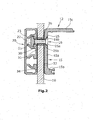
- a vertical section through the glass wall 10 and the support structure 12 is shown.
- the support structure 12 has on one side of the glass wall, the support rail 15 and on the opposite side a counter rail 20.
- the support rail 15 is substantially C-shaped. It has a base plate 15a, a lower leg 15b and an upper roof leg 15c. Through the base plate 15a, the screws 16 are inserted through and anchored on the opposite side (back) with nuts or Nutsteinen 21 in the counter rail 20.
- the counter rail 20 has longitudinal grooves 22 which receive the sliding blocks 21.
- the grooves 22 each have a longitudinal groove slot 23 whose edges are undercut.
- the sliding block 21 is designed elongated and it can be inserted through the slot slot 23 during assembly of the screw 16.
- the sliding block 21 takes the in Fig. 2 illustrated blocking position, in which it is aligned transversely to the longitudinal direction of the groove 22.
- the sliding block has an internal thread into which the external thread of the screw 16 is screwed. He can of the in Fig. 2 mounted on the left side and tightened from the right side.
- the screws 16 are inserted through holes 25 of the support rail 15 and further through corresponding holes 26 of the glass wall 10.
- the holes 25 each have a conical counterbore 25a for receiving the screw head.
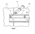
- the lowering part 25a is provided with lateral hollow channels 25b, which are also in Fig. 6 are visible.
- the channels 25b are used for injecting hardenable mass.
- the shaft 16b of the screw 16 has an undersize with respect to the bore 26.
- the outer diameter of the annular space is at least 10% larger than the outer diameter of the shaft 16b, in particular by at least 20% larger.
- a sleeve 31 made of plastic, which is intended to prevent direct contact of the shaft with the bore 26.
- the sleeve 31 is also located in the annulus.
- the annulus 30 provides the necessary for adjusting the support rail game.
- a cushion plate 33 to avoid direct contact between the metal of the support rail 15 and the glass.
- a corresponding padded disc 34 is provided between the counter-rail 20 and the glass wall 10. The pads have corresponding holes for the passage of the screws.
- the holes 25 are produced by the manufacturer.
- the holes 26 are also produced by the manufacturer.
- the glass walls are prepared for mounting the mounting rail. According to Fig. 4 the screws 16 are inserted into the support rail 15 so that they protrude on the back. In this form, the support rail 15 is set against the glass wall 10, wherein the screws 16 are inserted through the holes 26 of the glass wall.
- Fig. 4 shows the screwing a Nutsteines 21 on the screw 16.
- the sliding block is aligned horizontally, so that it fits into the corresponding groove of the counter rail.
- the counter rail is set against the back of the glass wall 10, wherein the sliding blocks 21 dive into the groove 22.
- each screw 16 can be rotated with a screwing tool, wherein the relevant sliding block 21 rotates by 90 ° until it is transversely oriented in the groove 22, as in Fig. 2 is shown.
- the screw 16 of the sliding block 21 is used to the screw head and the two rails 15 and 20 are stretched to clamp between them the glass wall 10. Before tightening can be done adjusting the alignment of the two rails 15 and 20.
- a squeezing tool 40 which has an injection tube 41 with a front tip 42.
- the squeezing tool 40 is a two-component squeezing tool that contains two components that make up the mass in separate form. When pressing the components are mixed together to initiate the curing process.
- the channels 25b lead into the annular space 30 between the screw 16 and the wall of the bore 26 (FIG. Fig. 2 ).
- the annulus is filled with the hardenable mass which hardens in the annulus.
- a final profile 44 is set, which closes the space containing the carriage 14 to the front.
- the glass of the sliding door 13 projects out of this space down.
Landscapes
- Engineering & Computer Science (AREA)
- Mechanical Engineering (AREA)
- Securing Of Glass Panes Or The Like (AREA)
Applications Claiming Priority (1)
| Application Number | Priority Date | Filing Date | Title |
|---|---|---|---|
| DE201010013585 DE102010013585A1 (de) | 2010-03-31 | 2010-03-31 | Verfahren zur Anbringung einer Tragschiene an einer Glaswand |
Publications (2)
| Publication Number | Publication Date |
|---|---|
| EP2372061A1 true EP2372061A1 (fr) | 2011-10-05 |
| EP2372061B1 EP2372061B1 (fr) | 2015-10-21 |
Family
ID=43978072
Family Applications (1)
| Application Number | Title | Priority Date | Filing Date |
|---|---|---|---|
| EP11160237.1A Active EP2372061B1 (fr) | 2010-03-31 | 2011-03-29 | Procédé d'application d'un rail de support sur une paroi en verre |
Country Status (2)
| Country | Link |
|---|---|
| EP (1) | EP2372061B1 (fr) |
| DE (1) | DE102010013585A1 (fr) |
Cited By (1)
| Publication number | Priority date | Publication date | Assignee | Title |
|---|---|---|---|---|
| AT523946B1 (de) * | 2021-03-23 | 2022-01-15 | Elmer Hubert | Ganzglasanlage mit glasschiebetür |
Families Citing this family (1)
| Publication number | Priority date | Publication date | Assignee | Title |
|---|---|---|---|---|
| EP4063600A1 (fr) * | 2021-03-23 | 2022-09-28 | Hubert Elmer | Installation tout verre pourvue de porte coulissante en verre |
Citations (2)
| Publication number | Priority date | Publication date | Assignee | Title |
|---|---|---|---|---|
| EP1025790A1 (fr) * | 1999-02-08 | 2000-08-09 | DORMA GmbH + Co. KG | Cloison de douche |
| EP1201840A2 (fr) * | 2000-10-26 | 2002-05-02 | Andreas Oswald GmbH | Système à parois de séparation sur pieds |
Family Cites Families (4)
| Publication number | Priority date | Publication date | Assignee | Title |
|---|---|---|---|---|
| DE20008684U1 (de) * | 2000-05-13 | 2001-09-20 | fischerwerke Artur Fischer GmbH & Co. KG, 72178 Waldachtal | Befestigungselement für ein Mehrscheibenglas und Anordnung in dem in einem plattenförmigen Mehrschichtkörper verankerten Befestigungselement |
| DE20019188U1 (de) * | 2000-11-10 | 2001-02-08 | Orbach, Joachim, 51545 Waldbröl | Vorrichtung zur Montage einer Verbundsicherheitsglasplatte |
| DE10325903B4 (de) * | 2002-10-26 | 2005-04-14 | Joachim Orbach | Vorrichtung für die Halterung von Platten |
| DE10329518B4 (de) * | 2003-06-30 | 2008-01-24 | Dorma Gmbh + Co. Kg | Führungseinrichtung für eine Schiebetür |
-
2010
- 2010-03-31 DE DE201010013585 patent/DE102010013585A1/de not_active Withdrawn
-
2011
- 2011-03-29 EP EP11160237.1A patent/EP2372061B1/fr active Active
Patent Citations (2)
| Publication number | Priority date | Publication date | Assignee | Title |
|---|---|---|---|---|
| EP1025790A1 (fr) * | 1999-02-08 | 2000-08-09 | DORMA GmbH + Co. KG | Cloison de douche |
| EP1201840A2 (fr) * | 2000-10-26 | 2002-05-02 | Andreas Oswald GmbH | Système à parois de séparation sur pieds |
Cited By (2)
| Publication number | Priority date | Publication date | Assignee | Title |
|---|---|---|---|---|
| AT523946B1 (de) * | 2021-03-23 | 2022-01-15 | Elmer Hubert | Ganzglasanlage mit glasschiebetür |
| AT523946A4 (de) * | 2021-03-23 | 2022-01-15 | Elmer Hubert | Ganzglasanlage mit glasschiebetür |
Also Published As
| Publication number | Publication date |
|---|---|
| EP2372061B1 (fr) | 2015-10-21 |
| DE102010013585A1 (de) | 2011-10-06 |
Similar Documents
| Publication | Publication Date | Title |
|---|---|---|
| DE20008684U1 (de) | Befestigungselement für ein Mehrscheibenglas und Anordnung in dem in einem plattenförmigen Mehrschichtkörper verankerten Befestigungselement | |
| EP2197623A1 (fr) | Procédé de fabrication de machines | |
| EP2372061B1 (fr) | Procédé d'application d'un rail de support sur une paroi en verre | |
| EP3078799A1 (fr) | Procédé de production de calages de fenêtres | |
| EP1076151A2 (fr) | Joint en T pour profilés creux et son mode d'assemblage | |
| DE3003867A1 (de) | Kraftschluessige und elastisch nachgiebige schienenbefestigung fuer gleisanlagen | |
| DE8707863U1 (de) | Bauelementesatz zum Anschließen eines Bauelementes an ein U-förmiges Profil | |
| DE102010003137B4 (de) | Ausgleichselement für eine Laufschiene sowie Verfahren zur Montage des Ausgleichselements | |
| DE2157202A1 (de) | Verfahren zur Herstellung von Bücherregalen oder Stellagen im allgemeinen sowie nach dem Verfahren erhaltene Regale | |
| DE102007045709B3 (de) | Betonschwelle und Verfahren zur Regulierung der Position von Schienen | |
| EP0180939B1 (fr) | Dispositif de maintien | |
| DE102014100688A1 (de) | Profilverbinder | |
| DE29920844U1 (de) | Freitragende Treppe | |
| EP3900589B1 (fr) | Dispositif de fixation pour deux panneaux de verre de sécurité composites agencés verticalement l'un par rapport à l'autre | |
| DE202017102916U1 (de) | Profilelement zur lastübertragenden Verbindung mit einer Abschattungseinrichtung und mit einem integrierten Zugelement | |
| EP0995670B1 (fr) | Procedé pour véhicule pour la fixation réglable des éléments | |
| DE29805785U1 (de) | Bohrlehre | |
| EP3309342A1 (fr) | Procédé de production de calages de fenêtres et dispositif d'application | |
| DE102020132441A1 (de) | System zur Befestigung, Anordnung zur Befestigung einer Schiene und Verfahren zur Reparatur einer solchen Anordnung | |
| DE69312940T2 (de) | Profil angewendet zur herstellung von elementen für zusammengeklebte strukturen und mit diesem hergestellte rettungsleiter | |
| DE202022105280U1 (de) | Höheneinstellung und Fixierung einer Glastrennwand | |
| EP2664254B1 (fr) | Procédé pour la fabrication d'un meuble avec plusiers tiroirs | |
| DE7417650U (de) | Übergangseinheit an Dehnfugen von Brücken und ähnlichen Bauwerken | |
| CH542370A (de) | Eckverbindung für längs eines Gehrungsschnittes aneinander liegende Hohlprofile | |
| DE202004001379U1 (de) | Bodenträgerschiene |
Legal Events
| Date | Code | Title | Description |
|---|---|---|---|
| PUAI | Public reference made under article 153(3) epc to a published international application that has entered the european phase |
Free format text: ORIGINAL CODE: 0009012 |
|
| AK | Designated contracting states |
Kind code of ref document: A1 Designated state(s): AL AT BE BG CH CY CZ DE DK EE ES FI FR GB GR HR HU IE IS IT LI LT LU LV MC MK MT NL NO PL PT RO RS SE SI SK SM TR |
|
| AX | Request for extension of the european patent |
Extension state: BA ME |
|
| 17P | Request for examination filed |
Effective date: 20120229 |
|
| GRAP | Despatch of communication of intention to grant a patent |
Free format text: ORIGINAL CODE: EPIDOSNIGR1 |
|
| 17Q | First examination report despatched |
Effective date: 20130724 |
|
| GRAP | Despatch of communication of intention to grant a patent |
Free format text: ORIGINAL CODE: EPIDOSNIGR1 |
|
| INTG | Intention to grant announced |
Effective date: 20150507 |
|
| GRAS | Grant fee paid |
Free format text: ORIGINAL CODE: EPIDOSNIGR3 |
|
| GRAA | (expected) grant |
Free format text: ORIGINAL CODE: 0009210 |
|
| AK | Designated contracting states |
Kind code of ref document: B1 Designated state(s): AL AT BE BG CH CY CZ DE DK EE ES FI FR GB GR HR HU IE IS IT LI LT LU LV MC MK MT NL NO PL PT RO RS SE SI SK SM TR |
|
| REG | Reference to a national code |
Ref country code: GB Ref legal event code: FG4D Free format text: NOT ENGLISH Ref country code: NL Ref legal event code: MP Effective date: 20151021 |
|
| REG | Reference to a national code |
Ref country code: CH Ref legal event code: EP |
|
| REG | Reference to a national code |
Ref country code: AT Ref legal event code: REF Ref document number: 756723 Country of ref document: AT Kind code of ref document: T Effective date: 20151115 |
|
| REG | Reference to a national code |
Ref country code: IE Ref legal event code: FG4D Free format text: LANGUAGE OF EP DOCUMENT: GERMAN |
|
| REG | Reference to a national code |
Ref country code: DE Ref legal event code: R096 Ref document number: 502011008145 Country of ref document: DE |
|
| REG | Reference to a national code |
Ref country code: LT Ref legal event code: MG4D |
|
| PG25 | Lapsed in a contracting state [announced via postgrant information from national office to epo] |
Ref country code: ES Free format text: LAPSE BECAUSE OF FAILURE TO SUBMIT A TRANSLATION OF THE DESCRIPTION OR TO PAY THE FEE WITHIN THE PRESCRIBED TIME-LIMIT Effective date: 20151021 Ref country code: IS Free format text: LAPSE BECAUSE OF FAILURE TO SUBMIT A TRANSLATION OF THE DESCRIPTION OR TO PAY THE FEE WITHIN THE PRESCRIBED TIME-LIMIT Effective date: 20160221 Ref country code: HR Free format text: LAPSE BECAUSE OF FAILURE TO SUBMIT A TRANSLATION OF THE DESCRIPTION OR TO PAY THE FEE WITHIN THE PRESCRIBED TIME-LIMIT Effective date: 20151021 Ref country code: LT Free format text: LAPSE BECAUSE OF FAILURE TO SUBMIT A TRANSLATION OF THE DESCRIPTION OR TO PAY THE FEE WITHIN THE PRESCRIBED TIME-LIMIT Effective date: 20151021 Ref country code: NO Free format text: LAPSE BECAUSE OF FAILURE TO SUBMIT A TRANSLATION OF THE DESCRIPTION OR TO PAY THE FEE WITHIN THE PRESCRIBED TIME-LIMIT Effective date: 20160121 Ref country code: NL Free format text: LAPSE BECAUSE OF FAILURE TO SUBMIT A TRANSLATION OF THE DESCRIPTION OR TO PAY THE FEE WITHIN THE PRESCRIBED TIME-LIMIT Effective date: 20151021 |
|
| PG25 | Lapsed in a contracting state [announced via postgrant information from national office to epo] |
Ref country code: GR Free format text: LAPSE BECAUSE OF FAILURE TO SUBMIT A TRANSLATION OF THE DESCRIPTION OR TO PAY THE FEE WITHIN THE PRESCRIBED TIME-LIMIT Effective date: 20160122 Ref country code: PL Free format text: LAPSE BECAUSE OF FAILURE TO SUBMIT A TRANSLATION OF THE DESCRIPTION OR TO PAY THE FEE WITHIN THE PRESCRIBED TIME-LIMIT Effective date: 20151021 Ref country code: LV Free format text: LAPSE BECAUSE OF FAILURE TO SUBMIT A TRANSLATION OF THE DESCRIPTION OR TO PAY THE FEE WITHIN THE PRESCRIBED TIME-LIMIT Effective date: 20151021 Ref country code: FI Free format text: LAPSE BECAUSE OF FAILURE TO SUBMIT A TRANSLATION OF THE DESCRIPTION OR TO PAY THE FEE WITHIN THE PRESCRIBED TIME-LIMIT Effective date: 20151021 Ref country code: SE Free format text: LAPSE BECAUSE OF FAILURE TO SUBMIT A TRANSLATION OF THE DESCRIPTION OR TO PAY THE FEE WITHIN THE PRESCRIBED TIME-LIMIT Effective date: 20151021 Ref country code: PT Free format text: LAPSE BECAUSE OF FAILURE TO SUBMIT A TRANSLATION OF THE DESCRIPTION OR TO PAY THE FEE WITHIN THE PRESCRIBED TIME-LIMIT Effective date: 20160222 Ref country code: RS Free format text: LAPSE BECAUSE OF FAILURE TO SUBMIT A TRANSLATION OF THE DESCRIPTION OR TO PAY THE FEE WITHIN THE PRESCRIBED TIME-LIMIT Effective date: 20151021 |
|
| REG | Reference to a national code |
Ref country code: DE Ref legal event code: R097 Ref document number: 502011008145 Country of ref document: DE |
|
| PG25 | Lapsed in a contracting state [announced via postgrant information from national office to epo] |
Ref country code: CZ Free format text: LAPSE BECAUSE OF FAILURE TO SUBMIT A TRANSLATION OF THE DESCRIPTION OR TO PAY THE FEE WITHIN THE PRESCRIBED TIME-LIMIT Effective date: 20151021 |
|
| PLBE | No opposition filed within time limit |
Free format text: ORIGINAL CODE: 0009261 |
|
| STAA | Information on the status of an ep patent application or granted ep patent |
Free format text: STATUS: NO OPPOSITION FILED WITHIN TIME LIMIT |
|
| PG25 | Lapsed in a contracting state [announced via postgrant information from national office to epo] |
Ref country code: SM Free format text: LAPSE BECAUSE OF FAILURE TO SUBMIT A TRANSLATION OF THE DESCRIPTION OR TO PAY THE FEE WITHIN THE PRESCRIBED TIME-LIMIT Effective date: 20151021 Ref country code: DK Free format text: LAPSE BECAUSE OF FAILURE TO SUBMIT A TRANSLATION OF THE DESCRIPTION OR TO PAY THE FEE WITHIN THE PRESCRIBED TIME-LIMIT Effective date: 20151021 Ref country code: EE Free format text: LAPSE BECAUSE OF FAILURE TO SUBMIT A TRANSLATION OF THE DESCRIPTION OR TO PAY THE FEE WITHIN THE PRESCRIBED TIME-LIMIT Effective date: 20151021 Ref country code: BE Free format text: LAPSE BECAUSE OF NON-PAYMENT OF DUE FEES Effective date: 20160331 Ref country code: SK Free format text: LAPSE BECAUSE OF FAILURE TO SUBMIT A TRANSLATION OF THE DESCRIPTION OR TO PAY THE FEE WITHIN THE PRESCRIBED TIME-LIMIT Effective date: 20151021 Ref country code: RO Free format text: LAPSE BECAUSE OF FAILURE TO SUBMIT A TRANSLATION OF THE DESCRIPTION OR TO PAY THE FEE WITHIN THE PRESCRIBED TIME-LIMIT Effective date: 20151021 |
|
| 26N | No opposition filed |
Effective date: 20160722 |
|
| PG25 | Lapsed in a contracting state [announced via postgrant information from national office to epo] |
Ref country code: LU Free format text: LAPSE BECAUSE OF FAILURE TO SUBMIT A TRANSLATION OF THE DESCRIPTION OR TO PAY THE FEE WITHIN THE PRESCRIBED TIME-LIMIT Effective date: 20160329 Ref country code: MC Free format text: LAPSE BECAUSE OF FAILURE TO SUBMIT A TRANSLATION OF THE DESCRIPTION OR TO PAY THE FEE WITHIN THE PRESCRIBED TIME-LIMIT Effective date: 20151021 |
|
| REG | Reference to a national code |
Ref country code: CH Ref legal event code: PL |
|
| GBPC | Gb: european patent ceased through non-payment of renewal fee |
Effective date: 20160329 |
|
| PG25 | Lapsed in a contracting state [announced via postgrant information from national office to epo] |
Ref country code: SI Free format text: LAPSE BECAUSE OF FAILURE TO SUBMIT A TRANSLATION OF THE DESCRIPTION OR TO PAY THE FEE WITHIN THE PRESCRIBED TIME-LIMIT Effective date: 20151021 |
|
| REG | Reference to a national code |
Ref country code: IE Ref legal event code: MM4A |
|
| REG | Reference to a national code |
Ref country code: FR Ref legal event code: ST Effective date: 20161130 |
|
| PG25 | Lapsed in a contracting state [announced via postgrant information from national office to epo] |
Ref country code: GB Free format text: LAPSE BECAUSE OF NON-PAYMENT OF DUE FEES Effective date: 20160329 Ref country code: LI Free format text: LAPSE BECAUSE OF NON-PAYMENT OF DUE FEES Effective date: 20160331 Ref country code: FR Free format text: LAPSE BECAUSE OF NON-PAYMENT OF DUE FEES Effective date: 20160331 Ref country code: CH Free format text: LAPSE BECAUSE OF NON-PAYMENT OF DUE FEES Effective date: 20160331 Ref country code: IE Free format text: LAPSE BECAUSE OF NON-PAYMENT OF DUE FEES Effective date: 20160329 |
|
| REG | Reference to a national code |
Ref country code: AT Ref legal event code: MM01 Ref document number: 756723 Country of ref document: AT Kind code of ref document: T Effective date: 20160329 |
|
| PG25 | Lapsed in a contracting state [announced via postgrant information from national office to epo] |
Ref country code: MT Free format text: LAPSE BECAUSE OF FAILURE TO SUBMIT A TRANSLATION OF THE DESCRIPTION OR TO PAY THE FEE WITHIN THE PRESCRIBED TIME-LIMIT Effective date: 20151021 Ref country code: AT Free format text: LAPSE BECAUSE OF NON-PAYMENT OF DUE FEES Effective date: 20160329 |
|
| PG25 | Lapsed in a contracting state [announced via postgrant information from national office to epo] |
Ref country code: HU Free format text: LAPSE BECAUSE OF FAILURE TO SUBMIT A TRANSLATION OF THE DESCRIPTION OR TO PAY THE FEE WITHIN THE PRESCRIBED TIME-LIMIT; INVALID AB INITIO Effective date: 20110329 Ref country code: CY Free format text: LAPSE BECAUSE OF FAILURE TO SUBMIT A TRANSLATION OF THE DESCRIPTION OR TO PAY THE FEE WITHIN THE PRESCRIBED TIME-LIMIT Effective date: 20151021 |
|
| PG25 | Lapsed in a contracting state [announced via postgrant information from national office to epo] |
Ref country code: MK Free format text: LAPSE BECAUSE OF FAILURE TO SUBMIT A TRANSLATION OF THE DESCRIPTION OR TO PAY THE FEE WITHIN THE PRESCRIBED TIME-LIMIT Effective date: 20151021 Ref country code: TR Free format text: LAPSE BECAUSE OF FAILURE TO SUBMIT A TRANSLATION OF THE DESCRIPTION OR TO PAY THE FEE WITHIN THE PRESCRIBED TIME-LIMIT Effective date: 20151021 |
|
| PG25 | Lapsed in a contracting state [announced via postgrant information from national office to epo] |
Ref country code: BG Free format text: LAPSE BECAUSE OF FAILURE TO SUBMIT A TRANSLATION OF THE DESCRIPTION OR TO PAY THE FEE WITHIN THE PRESCRIBED TIME-LIMIT Effective date: 20151021 |
|
| PG25 | Lapsed in a contracting state [announced via postgrant information from national office to epo] |
Ref country code: AL Free format text: LAPSE BECAUSE OF FAILURE TO SUBMIT A TRANSLATION OF THE DESCRIPTION OR TO PAY THE FEE WITHIN THE PRESCRIBED TIME-LIMIT Effective date: 20151021 |
|
| PGFP | Annual fee paid to national office [announced via postgrant information from national office to epo] |
Ref country code: IT Payment date: 20250331 Year of fee payment: 15 |
|
| PGFP | Annual fee paid to national office [announced via postgrant information from national office to epo] |
Ref country code: DE Payment date: 20260316 Year of fee payment: 16 |