EP2372073A1 - Fensterladenanordnung - Google Patents
Fensterladenanordnung Download PDFInfo
- Publication number
- EP2372073A1 EP2372073A1 EP10157922A EP10157922A EP2372073A1 EP 2372073 A1 EP2372073 A1 EP 2372073A1 EP 10157922 A EP10157922 A EP 10157922A EP 10157922 A EP10157922 A EP 10157922A EP 2372073 A1 EP2372073 A1 EP 2372073A1
- Authority
- EP
- European Patent Office
- Prior art keywords
- cloth
- rod
- roller
- unit
- window
- Prior art date
- Legal status (The legal status is an assumption and is not a legal conclusion. Google has not performed a legal analysis and makes no representation as to the accuracy of the status listed.)
- Withdrawn
Links
Images



Classifications
-
- E—FIXED CONSTRUCTIONS
- E06—DOORS, WINDOWS, SHUTTERS, OR ROLLER BLINDS IN GENERAL; LADDERS
- E06B—FIXED OR MOVABLE CLOSURES FOR OPENINGS IN BUILDINGS, VEHICLES, FENCES OR LIKE ENCLOSURES IN GENERAL, e.g. DOORS, WINDOWS, BLINDS, GATES
- E06B9/00—Screening or protective devices for wall or similar openings, with or without operating or securing mechanisms; Closures of similar construction
- E06B9/24—Screens or other constructions affording protection against light, especially against sunshine; Similar screens for privacy or appearance; Slat blinds
- E06B9/26—Lamellar or like blinds, e.g. venetian blinds
- E06B9/262—Lamellar or like blinds, e.g. venetian blinds with flexibly-interconnected horizontal or vertical strips; Concertina blinds, i.e. upwardly folding flexible screens
-
- E—FIXED CONSTRUCTIONS
- E06—DOORS, WINDOWS, SHUTTERS, OR ROLLER BLINDS IN GENERAL; LADDERS
- E06B—FIXED OR MOVABLE CLOSURES FOR OPENINGS IN BUILDINGS, VEHICLES, FENCES OR LIKE ENCLOSURES IN GENERAL, e.g. DOORS, WINDOWS, BLINDS, GATES
- E06B9/00—Screening or protective devices for wall or similar openings, with or without operating or securing mechanisms; Closures of similar construction
- E06B9/24—Screens or other constructions affording protection against light, especially against sunshine; Similar screens for privacy or appearance; Slat blinds
- E06B2009/2423—Combinations of at least two screens
- E06B2009/2447—Parallel screens
- E06B2009/2452—Parallel screens moving independently
-
- E—FIXED CONSTRUCTIONS
- E06—DOORS, WINDOWS, SHUTTERS, OR ROLLER BLINDS IN GENERAL; LADDERS
- E06B—FIXED OR MOVABLE CLOSURES FOR OPENINGS IN BUILDINGS, VEHICLES, FENCES OR LIKE ENCLOSURES IN GENERAL, e.g. DOORS, WINDOWS, BLINDS, GATES
- E06B9/00—Screening or protective devices for wall or similar openings, with or without operating or securing mechanisms; Closures of similar construction
- E06B9/24—Screens or other constructions affording protection against light, especially against sunshine; Similar screens for privacy or appearance; Slat blinds
- E06B2009/2423—Combinations of at least two screens
- E06B2009/2447—Parallel screens
- E06B2009/2458—Parallel screens moving simultaneously
-
- E—FIXED CONSTRUCTIONS
- E06—DOORS, WINDOWS, SHUTTERS, OR ROLLER BLINDS IN GENERAL; LADDERS
- E06B—FIXED OR MOVABLE CLOSURES FOR OPENINGS IN BUILDINGS, VEHICLES, FENCES OR LIKE ENCLOSURES IN GENERAL, e.g. DOORS, WINDOWS, BLINDS, GATES
- E06B9/00—Screening or protective devices for wall or similar openings, with or without operating or securing mechanisms; Closures of similar construction
- E06B9/24—Screens or other constructions affording protection against light, especially against sunshine; Similar screens for privacy or appearance; Slat blinds
- E06B9/26—Lamellar or like blinds, e.g. venetian blinds
- E06B9/262—Lamellar or like blinds, e.g. venetian blinds with flexibly-interconnected horizontal or vertical strips; Concertina blinds, i.e. upwardly folding flexible screens
- E06B2009/2622—Gathered vertically; Roman, Austrian or festoon blinds
-
- E—FIXED CONSTRUCTIONS
- E06—DOORS, WINDOWS, SHUTTERS, OR ROLLER BLINDS IN GENERAL; LADDERS
- E06B—FIXED OR MOVABLE CLOSURES FOR OPENINGS IN BUILDINGS, VEHICLES, FENCES OR LIKE ENCLOSURES IN GENERAL, e.g. DOORS, WINDOWS, BLINDS, GATES
- E06B9/00—Screening or protective devices for wall or similar openings, with or without operating or securing mechanisms; Closures of similar construction
- E06B9/24—Screens or other constructions affording protection against light, especially against sunshine; Similar screens for privacy or appearance; Slat blinds
- E06B9/40—Roller blinds
Definitions
- the present invention relates to a window blind assembly, more particularly to a window blind assembly that is aesthetically pleasing, structurally simple, and easily taken apart for cleaning.
- the conventional roller blind has a roller blind cloth and a roller rod mounted to a window.
- the roller blind cloth is connected to the roller rod, and may be wound around and unwound from the roller rod by rotating the roller rod, thereby either covering or uncovering the window.
- the roman blind has a curtain cloth mounted to an inner side of a window, and one side of the curtain cloth is provided with some guide rings. Some cords extend through the guide rings, and are then connected to a bottom portion of the curtain cloth. Manipulation of the cords results in folding and unfolding of the curtain cloth.
- the conventional roller blind has an unsophisticated appearance.
- the conventional roman blind on the other hand, is not easily taken apart for cleaning. There is a need for a new curtain structurethat deals with these issues.
- the object of the present invention is to provide a window blind assembly, which combines aspects of a roller blind and a roman blind, has a structure that is simple, and is low in cost.
- a window blind assembly of the present invention is adapted for being mounted to a window.
- the window blind assembly comprises a roller blind unit, a curtain member unit, and a clamping unit.
- the roller blind unit includes a roller rod that extends horizontally and that is rotatably mounted at or in proximity to an upper edge portion of the window, and a roller blind cloth a top edge of which is connected to the roller rod and which is able to be wound around and extended from the roller rod.
- the curtain member unit includes a folding curtain cloth a top edge of which is mounted at or around the upper edge of the window.
- the clamping unit includes a connecting clamp that extends horizontally, and has a first clamping portion that clamps onto the folding curtain cloth and a second clamping portion that clamps onto the roller blind cloth.
- a first preferred embodiment of a window blind assembly of the present invention is adapted for being mounted to a window 2.
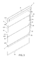
- the window blind assembly includes a roller blind unit 3, a curtain member unit 4, and a clamping unit 5 disposed between and interconnecting the roller blind unit 3 and the curtain member unit 4.
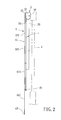
- the roller blind unit 3 includes a roller rod 32, a roller blind cloth 34, a horizontal frame 31, a weighting rod 35, and a cord 33.
- the roller rod 32 extends horizontally and is rotatably mounted at or in proximity to an upper edge portion of the window 2.
- the roller blind cloth 34 has a top edge connected to the roller rod 32, and the roller blind cloth 34 is able to be wound around and extended from the roller rod 32.
- the horizontal frame 31 is mounted at least partially surrounding the roller rod 32.
- the weighting rod 35 extends horizontally and is connected to a bottom edge of the roller blind cloth 34.
- the weighting rod 35 pulls down on the roller blind cloth 34 to flatten the same by virtue of its weight.
- the cord 33 is coupled to the roller rod 32 for controlling rotation of the same such that the roller blind cloth 34 is wound around or extended from the roller rod 32.
- the roller blind unit 3 is manipulated by pulling the cord 33 to drive the roller rod 32 such that the roller blind cloth 34 is wound around the roller rod 32 or extended downwardly.
- a section of the curtain member unit 4 clamped by the connecting clamp 50 is displaced upwardly, such that the curtain member unit 4 is folded. This will be described in greater detail below.
- the roller rod 32 may be driven by the cord 33 as described above, or can be driven by a motor (not shown), or can be driven through a spring mechanism (not shown) . Therefore, the driving method is not limited to the embodiment described herein.
- the curtain member unit 4 includes a folding curtain cloth 41, a fastening member 42, and a rod 43.
- the folding curtain cloth 41 has a top edge mounted at or around the upper edge of the window 2, and the folding curtain cloth 41 is disposed in front of the roller blind cloth 34.
- the fastening member 42 interconnects the horizontal frame 31 and the top edge of the folding curtain cloth 41.
- the horizontal frame 31 may be made of a fabric material
- the fastening member 42 may be a hook fastener, such as that found in a Velcro ® fastener, and the fastening member 42 may attach to the fabric material of the horizontal frame 31 through a hook-and-loop engagement with the horizontal frame 31.
- the rod 43 horizontally extends and is connected to a bottom edge of the folding curtain cloth 41.
- the folding curtain cloth 41 has a sheltering portion 411 and three sleeving portions 416.
- Each of the sleeving portions 416 extends horizontally, and is connected to a rear surface of the sheltering portion 411 of the folding curtain cloth 41.
- the sheltering portion 411 has a first cloth segment 412, a second cloth segment 413, a third cloth segment 414, and a fourth cloth segment 415, which are arranged vertically in this order.
- the sleeving portions 416 horizontally extend, and are respectively disposed at connecting portions between the first cloth segment 412 and the second cloth segment 413, between the second cloth segment 413 and the third cloth segment 414, and between the third cloth segment 414 and the fourth cloth segment 415.
- the clamping unit 5 includes three connecting clamps 50 and three connecting tubes 53.
- the connecting clamps 50 extend horizontally and are vertically spaced apart from each other.
- the connecting clamp 50 has a first clamping portion 51 that clamps onto the folding curtain cloth 41 and a second clamping portion 52 that clamps onto the roller blind cloth 34.
- the connecting tube 53 extends horizontally on a rear surface of the roller blind cloth 34, and is connected to a respective one of the second clamping portions 52 of the connecting clamps 50 .
- the first clamping portion 51 of the connecting clamp 50 has a front rod 511 and a rear rod 512 which are disposed adjacent to each other and end portions of which are connected to each other.
- the front rod 511 and the rear rod 512 of the first clamping portion 51 define a first slot 513 for clamping onto the folding curtain cloth 41.
- the front rod 511 of the first clamping portion 51 is inserted into a respective one of the sleeving portions 416, such that the first clamping portion 51 clamps onto the sleeving portion 416.
- the second clamping portion 52 has a front rod 521 and a rear rod 522 disposed adjacent to each other and end portions of which are connected to each other.
- the front rod 521 and the rear rod 522 of the second clamping portion 52 define a second slot 523 for clamping onto the roller blind cloth 34.
- the front rod 521 of the second clamping portion 52 is coupled to the rear rod 512 of the first clamping portion 51.
- a metal rod can be bent to form the connecting clamp 50.
- the connecting clamp 50 can be formed using plastic material. Hence, the present invention is not limited with respect to the material and fabricating method used for the connecting clamp 50.
- the connecting tube 53 is sleeved on the rear rod 522 of the second clamping portion 52 of the connecting clamp 50. End portions of the connecting tube 53 of the clamping unit 5 are formed with slits 532 that extend horizontally and facilitate inserting of the rear rod 522 of the second clamping portion 52 into the connecting tube 53.
- An inner surface of the connecting tube 53 of the clamping unit 5 is formed with a plurality of lengthwise ribs 533. The ribs 533 are used for enhancing the strength of the connecting tube 53 so as to prevent the same from being bent when in use.
- the roller blind cloth 34 of the roller blind unit 3 and the folding curtain cloth 41 of the curtain member unit 4 are respectively unwound and unfolded downwardly when the window 2 is covered.
- the roller blind cloth 34 of the roller blind unit 3 is wound upwardly by pulling the cord 33 of the roller blind unit 3 which results in rotation of the roller rod 32.
- the weighting rod 35 moves upwardly to first push against the lowest connecting clamp 50 and the lowest connecting tube 53, and to subsequently displace the lowest connecting clamp 50 and the lowest connecting tube 53 in an upward direction.
- the third cloth segment 414 is folded as shown in Figure 6 .
- this process is repeated with the continued winding of the roller blind cloth 34, such that the roller blind cloth 34 is fully wound around the roller rod 32, and the second cloth segment 413 and the first cloth segment 412 are eventually folded upwardly as shown in Figures 7 and 8 .
- Figures 7 and 8 show that the folded curtain member unit 4 has a sophisticated, classic appearance.
- the roller blind unit 3 is provided with the folding curtain cloth 41 and the clamping unit 5 is mounted between the curtain member unit 4 and the roller blind unit 3.
- the folding curtain cloth 41 uses the fastening member 42 for attachment to the horizontal frame 31. Accordingly, by simply removing the fastening member 42 and the connecting clamps 50, the folding curtain cloth 41 can be removed for cleaning or for replacement with another folding curtain cloth 41 with a different style.
- the slit 532 of the connecting tube 53 of the clamping unit 5 allows for convenient insertion of the rear rod 522 of the connecting clamp 50 into the connecting tube 53.
- Figure 9 illustrates a second preferred embodiment of the window blind assembly according to the present invention.
- the second preferred embodiment differs from the first preferred embodiment in the following aspects.
- the connecting tube 53 of each of the connecting clamps 50 extends into a respective one of the sleeving portions 416, and is sleeved on the front rod 511 of the first clamping portion 51 of the corresponding connecting clamp 50. During the process of being folded upwardly, the connecting tube 53 can horizontally support the folding curtain cloth 41.
Landscapes
- Engineering & Computer Science (AREA)
- Structural Engineering (AREA)
- Architecture (AREA)
- Civil Engineering (AREA)
- Curtains And Furnishings For Windows Or Doors (AREA)
Priority Applications (1)
| Application Number | Priority Date | Filing Date | Title |
|---|---|---|---|
| EP10157922A EP2372073A1 (de) | 2010-03-26 | 2010-03-26 | Fensterladenanordnung |
Applications Claiming Priority (1)
| Application Number | Priority Date | Filing Date | Title |
|---|---|---|---|
| EP10157922A EP2372073A1 (de) | 2010-03-26 | 2010-03-26 | Fensterladenanordnung |
Publications (1)
| Publication Number | Publication Date |
|---|---|
| EP2372073A1 true EP2372073A1 (de) | 2011-10-05 |
Family
ID=42753373
Family Applications (1)
| Application Number | Title | Priority Date | Filing Date |
|---|---|---|---|
| EP10157922A Withdrawn EP2372073A1 (de) | 2010-03-26 | 2010-03-26 | Fensterladenanordnung |
Country Status (1)
| Country | Link |
|---|---|
| EP (1) | EP2372073A1 (de) |
Cited By (4)
| Publication number | Priority date | Publication date | Assignee | Title |
|---|---|---|---|---|
| WO2012072972A1 (en) * | 2010-12-01 | 2012-06-07 | Louver-Lite Limited | Blind assembly |
| WO2012109501A1 (en) * | 2011-02-10 | 2012-08-16 | Hunter Douglas, Inc. | Band lift system for shades |
| GB2501797A (en) * | 2012-02-27 | 2013-11-06 | Fourds Ltd | Screen Assembly |
| EP4001580A1 (de) * | 2020-11-17 | 2022-05-25 | Trenomat GmbH & Co. KG | Trennvorhang für beispielsweise sporthallen |
Citations (3)
| Publication number | Priority date | Publication date | Assignee | Title |
|---|---|---|---|---|
| FR2203013A1 (de) * | 1972-10-18 | 1974-05-10 | Quiot Andre | |
| GB1461395A (en) * | 1973-03-13 | 1977-01-13 | Beauty Blinds Ltd | Curtain mounting assembly |
| GB2389074A (en) * | 2002-05-30 | 2003-12-03 | Louver Lite Ltd | Blind fabric |
-
2010
- 2010-03-26 EP EP10157922A patent/EP2372073A1/de not_active Withdrawn
Patent Citations (3)
| Publication number | Priority date | Publication date | Assignee | Title |
|---|---|---|---|---|
| FR2203013A1 (de) * | 1972-10-18 | 1974-05-10 | Quiot Andre | |
| GB1461395A (en) * | 1973-03-13 | 1977-01-13 | Beauty Blinds Ltd | Curtain mounting assembly |
| GB2389074A (en) * | 2002-05-30 | 2003-12-03 | Louver Lite Ltd | Blind fabric |
Cited By (7)
| Publication number | Priority date | Publication date | Assignee | Title |
|---|---|---|---|---|
| WO2012072972A1 (en) * | 2010-12-01 | 2012-06-07 | Louver-Lite Limited | Blind assembly |
| WO2012109501A1 (en) * | 2011-02-10 | 2012-08-16 | Hunter Douglas, Inc. | Band lift system for shades |
| US9267324B2 (en) | 2011-02-10 | 2016-02-23 | Hunter Douglas, Inc. | Band lift system for shades |
| US10392858B2 (en) | 2011-02-10 | 2019-08-27 | Hunter Douglas Inc. | Band lift system for shades |
| GB2501797A (en) * | 2012-02-27 | 2013-11-06 | Fourds Ltd | Screen Assembly |
| GB2501797B (en) * | 2012-02-27 | 2016-03-09 | Fourds Ltd | Screen assembly |
| EP4001580A1 (de) * | 2020-11-17 | 2022-05-25 | Trenomat GmbH & Co. KG | Trennvorhang für beispielsweise sporthallen |
Similar Documents
| Publication | Publication Date | Title |
|---|---|---|
| US8186411B2 (en) | Window blind assembly | |
| US20110203742A1 (en) | Window blind assembly | |
| US6662845B1 (en) | Roman shade with separated backing sheet | |
| US20110186240A1 (en) | Roman curtain | |
| TWM256434U (en) | Curtain Venetian blinds | |
| EP2372073A1 (de) | Fensterladenanordnung | |
| US7100661B1 (en) | Awning topper curtain rod extender | |
| US20060048902A1 (en) | Raisable panel | |
| US20120273140A1 (en) | Apparatus, system, and method for covering a window | |
| US20120305199A1 (en) | Window Covering and Method of Making the Same | |
| AU2004201848A1 (en) | Raisable panel | |
| EP2369119A1 (de) | Fensterjalousienanordnung | |
| US20070000618A1 (en) | Roman blind assembly | |
| US5230375A (en) | Curtain system and method | |
| AU2010200750B2 (en) | Window blind assembly | |
| CN2545343Y (zh) | 轻便型横式布帘百叶窗 | |
| CA2695353A1 (en) | Window blind assembly | |
| EP2369123A1 (de) | Fensterladenanordnung | |
| US20100224331A1 (en) | Panels of Fabric and Associated Assemblies for a Window Treatment | |
| US20120273139A1 (en) | Apparatus, system, and method for covering a window | |
| CN212815589U (zh) | 一种多功能展示墙 | |
| JP2002332785A (ja) | 日射遮蔽装置 | |
| US20230042499A1 (en) | Roman shade | |
| AU2010200746B2 (en) | Window blind assembly | |
| TW201113420A (en) | Roller blind device |
Legal Events
| Date | Code | Title | Description |
|---|---|---|---|
| PUAI | Public reference made under article 153(3) epc to a published international application that has entered the european phase |
Free format text: ORIGINAL CODE: 0009012 |
|
| 17P | Request for examination filed |
Effective date: 20110418 |
|
| AK | Designated contracting states |
Kind code of ref document: A1 Designated state(s): AT BE BG CH CY CZ DE DK EE ES FI FR GB GR HR HU IE IS IT LI LT LU LV MC MK MT NL NO PL PT RO SE SI SK SM TR |
|
| STAA | Information on the status of an ep patent application or granted ep patent |
Free format text: STATUS: THE APPLICATION IS DEEMED TO BE WITHDRAWN |
|
| 18D | Application deemed to be withdrawn |
Effective date: 20141001 |