EP2372086A2 - Kühlkreislauf für eine Turbinenrotorschaufel und zugehöriges Kühlverfahren - Google Patents
Kühlkreislauf für eine Turbinenrotorschaufel und zugehöriges Kühlverfahren Download PDFInfo
- Publication number
- EP2372086A2 EP2372086A2 EP11159290A EP11159290A EP2372086A2 EP 2372086 A2 EP2372086 A2 EP 2372086A2 EP 11159290 A EP11159290 A EP 11159290A EP 11159290 A EP11159290 A EP 11159290A EP 2372086 A2 EP2372086 A2 EP 2372086A2
- Authority
- EP
- European Patent Office
- Prior art keywords
- airfoil
- cooling circuit
- cooling
- platform
- passage
- Prior art date
- Legal status (The legal status is an assumption and is not a legal conclusion. Google has not performed a legal analysis and makes no representation as to the accuracy of the status listed.)
- Withdrawn
Links
- 238000001816 cooling Methods 0.000 title claims abstract description 221
- 230000002093 peripheral effect Effects 0.000 claims description 14
- 238000000034 method Methods 0.000 claims description 11
- 238000004519 manufacturing process Methods 0.000 description 3
- 230000001154 acute effect Effects 0.000 description 2
- WYTGDNHDOZPMIW-RCBQFDQVSA-N alstonine Natural products C1=CC2=C3C=CC=CC3=NC2=C2N1C[C@H]1[C@H](C)OC=C(C(=O)OC)[C@H]1C2 WYTGDNHDOZPMIW-RCBQFDQVSA-N 0.000 description 2
- 238000005553 drilling Methods 0.000 description 2
- 238000000605 extraction Methods 0.000 description 2
- 241000879887 Cyrtopleura costata Species 0.000 description 1
- 230000009286 beneficial effect Effects 0.000 description 1
- 238000005266 casting Methods 0.000 description 1
- 238000010276 construction Methods 0.000 description 1
- 239000002826 coolant Substances 0.000 description 1
- 238000005336 cracking Methods 0.000 description 1
- 230000009429 distress Effects 0.000 description 1
- 238000010304 firing Methods 0.000 description 1
- 230000000977 initiatory effect Effects 0.000 description 1
- 238000012986 modification Methods 0.000 description 1
- 230000004048 modification Effects 0.000 description 1
- 230000003647 oxidation Effects 0.000 description 1
- 238000007254 oxidation reaction Methods 0.000 description 1
Images


Classifications
-
- F—MECHANICAL ENGINEERING; LIGHTING; HEATING; WEAPONS; BLASTING
- F01—MACHINES OR ENGINES IN GENERAL; ENGINE PLANTS IN GENERAL; STEAM ENGINES
- F01D—NON-POSITIVE DISPLACEMENT MACHINES OR ENGINES, e.g. STEAM TURBINES
- F01D5/00—Blades; Blade-carrying members; Heating, heat-insulating, cooling or antivibration means on the blades or the members
- F01D5/02—Blade-carrying members, e.g. rotors
- F01D5/08—Heating, heat-insulating or cooling means
- F01D5/081—Cooling fluid being directed on the side of the rotor disc or at the roots of the blades
- F01D5/082—Cooling fluid being directed on the side of the rotor disc or at the roots of the blades on the side of the rotor disc
-
- F—MECHANICAL ENGINEERING; LIGHTING; HEATING; WEAPONS; BLASTING
- F05—INDEXING SCHEMES RELATING TO ENGINES OR PUMPS IN VARIOUS SUBCLASSES OF CLASSES F01-F04
- F05D—INDEXING SCHEME FOR ASPECTS RELATING TO NON-POSITIVE-DISPLACEMENT MACHINES OR ENGINES, GAS-TURBINES OR JET-PROPULSION PLANTS
- F05D2240/00—Components
- F05D2240/80—Platforms for stationary or moving blades
- F05D2240/81—Cooled platforms
-
- F—MECHANICAL ENGINEERING; LIGHTING; HEATING; WEAPONS; BLASTING
- F05—INDEXING SCHEMES RELATING TO ENGINES OR PUMPS IN VARIOUS SUBCLASSES OF CLASSES F01-F04
- F05D—INDEXING SCHEME FOR ASPECTS RELATING TO NON-POSITIVE-DISPLACEMENT MACHINES OR ENGINES, GAS-TURBINES OR JET-PROPULSION PLANTS
- F05D2250/00—Geometry
- F05D2250/10—Two-dimensional
- F05D2250/18—Two-dimensional patterned
- F05D2250/185—Two-dimensional patterned serpentine-like
-
- F—MECHANICAL ENGINEERING; LIGHTING; HEATING; WEAPONS; BLASTING
- F05—INDEXING SCHEMES RELATING TO ENGINES OR PUMPS IN VARIOUS SUBCLASSES OF CLASSES F01-F04
- F05D—INDEXING SCHEME FOR ASPECTS RELATING TO NON-POSITIVE-DISPLACEMENT MACHINES OR ENGINES, GAS-TURBINES OR JET-PROPULSION PLANTS
- F05D2260/00—Function
- F05D2260/20—Heat transfer, e.g. cooling
- F05D2260/205—Cooling fluid recirculation, i.e. after cooling one or more components is the cooling fluid recovered and used elsewhere for other purposes
Definitions
- the present invention relates generally to gas turbine buckets or blades and particularly relates to cooling a so-called platform portion interposed between the bucket airfoil and the bucket shank.
- the present invention relates to a cooling circuit for a turbine bucket having a shank portion, a platform portion and an airfoil portion, the cooling circuit comprising a first cooling passage extending from a cooling air inlet located at a radially inward end of said shank portion so as to communicate with a turbine wheelspace when in use, said first cooling passage connecting to a second cooling passage extending within and across at least one region of said platform, said second cooling passage connecting with a third cooling passage extending radially outwardly in said airfoil portion, said third cooling passage terminating at one or more cooling air outlets located at a radially outward end of said airfoil portion.
- the invention in another exemplary but nonlimiting embodiment, relates to a cooling circuit for a turbine bucket having a shank, a platform and an airfoil, the cooling circuit comprising: a first cooling passage extending from an inlet located at a radially inward end of the shank and adapted to communicate with a turbine wheel-space, the first cooling passage, in use, supplying cooling air to a serpentine cooling circuit extending within and across at least one region of the platform, said serpentine cooling circuit connecting with a separate internal cooling circuit passage proximate a trailing edge of the airfoil, such that the cooling air used to cool the platform is re-used in the airfoil cooling circuit; wherein the platform includes a first region on a pressure side of the airfoil portion and a second region on a suction side of the airfoil portion, the at least one region comprising the first region on the pressure side of the airfoil.
- the invention provides a method of cooling a gas turbine bucket platform comprising: extracting compressor cooling air from a wheel space area between blade wheels mounted on a turbine rotor; feeding extracted compressor cooling air from a radially oriented passage along a leading edge of a shank portion of the bucket to a serpentine cooling passage formed in the platform; dumping the extracted compressor cooling air into an internal cooling circuit in the bucket airfoil; and exhausting the extracted compressor cooling air along a trailing edge of the bucket airfoil.
- the present invention relates to a turbine bucket platform cooling arrangement where a portion of the compressor-extracted air that is used to cool the wheel space areas between the rotor wheels is fed to the bucket platform through a passage on the lower outlet side of the bucket shank portion.
- This passage will feed the extracted air radially outwardly to the platform where it will turn substantially 90 degrees and follow a serpentine passage along and around the "inner portion" of the platform, i.e., that portion on the pressure side of the bucket airfoil.
- the extracted cooling air will then dump into one of the radially-extending internal core cooling passages of the bucket airfoil to be used for airfoil cooling.
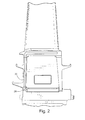
- a turbine bucket 10 includes an airfoil 12 and a shank 14, typically formed with so-called angel-wing seals 16.
- a relatively flat platform 18 is located radially between the airfoil 12 and the shank 14.
- a cooling air inlet passage 20 is formed (e.g., drilled or cast) in a forward or leading face 22 of the bucket shank 14.
- the inlet passage 20 extends radially outwardly to the platform 18 where it turns substantially 90 degrees into a platform cooling circuit generally indicated at 24.
- the inlet 26 to the radial passage 20 is radially aligned with the passage 20.
- Fig. 2 illustrates an alternative arrangement by where the inlet 28 to the passage 20 is formed at an acute angle to the passage, illustrating an alternative manufacturing expedient.
- the construction is otherwise substantially identical to that shown in Fig. 1 , and either inlet arrangement may be employed with each of the serpentine cooling circuits described below.
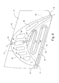
- a serpentine cooling circuit 24 for cooling the platform 18 is shown in accordance with one exemplary but nonlimiting embodiment.
- the bucket airfoil 12 has a suction side 30, a pressure side 32, a leading edge 34 and a trailing edge 36.
- the inlet passage 20 is located along the leading edge of the shank 14, adjacent the leading edge 34 of the airfoil.
- the serpentine cooling circuit 24 is formed within the platform 18 (by e.g., casting) so as to provide a first cooling passage section 38 that serves to cool an area proximate the pressure side 32 of the airfoil and including the fillet area where the airfoil 12 is joined to the platform 18.
- the cooling flow then reverses through a cooling passage section 40 in a middle region of the platform, and then reverses again in a cooling passage section 42 that runs proximate an edge 44 of the platform.
- the circuit then turns substantially 90° in a cooling passage section 46 and then dumps the cooling air into a radially extending internal airfoil cooling passage 48 closest to the airfoil trailing edge 36.
- the radial cooling passage 48 is part of an internal serpentine cooling circuit in the airfoil 12 which includes a number of radial connected passages 50, 52, 54, 56, 58 and 48.
- the coolant flows through the circuit in a direction from the leading edge to the trailing edge, exiting the airfoil through plural passages 60 extending from the radial passage 48 to the trailing edge 36.
- Fig. 4 shows an alternative serpentine cooling circuit 124 for cooling the platform 18.
- the inlet passage 20 remains adjacent the leading edge 34 of the airfoil 12.
- a first cooling passage section 62 of the cooling circuit 124 runs along the edge 44 of the platform 18 and then reverses in a cooling passage section 64 along a middle region of the platform before reversing again in a cooling passage section 66 closer to the suction side 32 of the bucket airfoil.
- the cooling circuit then reverses through a cooling passage section 68 and turns into the middle portion of the airfoil via cooling passage section 70 where it dumps into the radially-extending internal airfoil cooling passage 56.
- the internal airfoil cooling circuit remains as described above in connection with Fig. 3 .
- the cooling passage section 70 is more easily formed by initiating a drilling operation from the opposite edge 76 of the platform 18, forming an extending cooling passage section 72.
- the extended cooling passage section 72 is plugged at 74.
- the otherwise relatively short cooling passage section 72 may provide some additional, albeit minor, cooling to the platform.
- Fig. 5 illustrates a third exemplary but nonlimiting embodiment of a suitable serpentine cooling circuit.
- This cooling circuit 224 contains the same cooling passage sections 62, 64 and 66 as shown in Fig. 4 . In this embodiment, however, the cooling circuit 224 again dumps into the trailing edge airfoil cavity 48 as in the first described embodiment, via a cooling passage section 78.
- the manufacture of cooling passage section 78 is facilitated by drilling an extended passage 80 through the platform, on the suction side 30 of the airfoil 12, plugged at 82, similar to the manner in which passage section 72 is plugged at 74 in Fig. 4 . Because of the length of the extended passage section 80, some meaningful cooling of the suction side of the platform 18 is provided.
- the serpentine cooling circuit 24, 124 and 224 formed in the bucket platform 18 is fed from compressor-extraction air taken in at the lower, leading side of the bucket shank.
- the cooling air is then routed along the serpentine platform cooling circuit before being dumped into the internal airfoil cooling circuit where the platform cooling air is re-used for cooling the airfoil.
- the cooling air is then exhausted through the trailing edge of the bucket along with the airfoil cooling circuit air.
- This arrangement effectively film cools both the forward face of the shank and the platform, while providing additional cooling air to the airfoil.
- pulling compressor extraction air directly into the bucket provides air at higher pressure to the problematic platform area which helps reduce the platform temperature and prolong the life of the bucket. This, in turn, results in reduced repair costs over the service life of the bucket.
Landscapes
- Engineering & Computer Science (AREA)
- Mechanical Engineering (AREA)
- General Engineering & Computer Science (AREA)
- Turbine Rotor Nozzle Sealing (AREA)
Applications Claiming Priority (1)
| Application Number | Priority Date | Filing Date | Title |
|---|---|---|---|
| US12/732,610 US8444381B2 (en) | 2010-03-26 | 2010-03-26 | Gas turbine bucket with serpentine cooled platform and related method |
Publications (1)
| Publication Number | Publication Date |
|---|---|
| EP2372086A2 true EP2372086A2 (de) | 2011-10-05 |
Family
ID=44021918
Family Applications (1)
| Application Number | Title | Priority Date | Filing Date |
|---|---|---|---|
| EP11159290A Withdrawn EP2372086A2 (de) | 2010-03-26 | 2011-03-22 | Kühlkreislauf für eine Turbinenrotorschaufel und zugehöriges Kühlverfahren |
Country Status (4)
| Country | Link |
|---|---|
| US (1) | US8444381B2 (de) |
| EP (1) | EP2372086A2 (de) |
| JP (1) | JP2011208639A (de) |
| CN (1) | CN102200032A (de) |
Cited By (5)
| Publication number | Priority date | Publication date | Assignee | Title |
|---|---|---|---|---|
| EP2634369A1 (de) * | 2012-03-01 | 2013-09-04 | General Electric Company | Turbinenschaufel und zugehöriges Kühlverfahren |
| EP2944761A1 (de) * | 2014-04-04 | 2015-11-18 | United Technologies Corporation | Gasturbinenmotorkomponente mit plattformkühlung |
| EP3156609A1 (de) * | 2015-10-12 | 2017-04-19 | General Electric Company | Turbinenleitschaufel mit auslassplenum für kühlluft |
| EP3156607A1 (de) * | 2015-10-12 | 2017-04-19 | General Electric Company | Turbinenleitschaufeln mit gekühltem inneren deckband |
| CN113153440A (zh) * | 2020-01-22 | 2021-07-23 | 通用电气公司 | 增材制造的具有带格栅支撑结构的中空安装架的涡轮转子叶片根部 |
Families Citing this family (17)
| Publication number | Priority date | Publication date | Assignee | Title |
|---|---|---|---|---|
| US8636471B2 (en) * | 2010-12-20 | 2014-01-28 | General Electric Company | Apparatus and methods for cooling platform regions of turbine rotor blades |
| US8628300B2 (en) * | 2010-12-30 | 2014-01-14 | General Electric Company | Apparatus and methods for cooling platform regions of turbine rotor blades |
| US9022735B2 (en) | 2011-11-08 | 2015-05-05 | General Electric Company | Turbomachine component and method of connecting cooling circuits of a turbomachine component |
| US9249674B2 (en) * | 2011-12-30 | 2016-02-02 | General Electric Company | Turbine rotor blade platform cooling |
| US9021816B2 (en) * | 2012-07-02 | 2015-05-05 | United Technologies Corporation | Gas turbine engine turbine vane platform core |
| EP2886798B1 (de) | 2013-12-20 | 2018-10-24 | Rolls-Royce Corporation | Mechanisch bearbeitete Filmkühl-Bohrungen |
| US10030523B2 (en) * | 2015-02-13 | 2018-07-24 | United Technologies Corporation | Article having cooling passage with undulating profile |
| US9957815B2 (en) | 2015-03-05 | 2018-05-01 | United Technologies Corporation | Gas powered turbine component including serpentine cooling |
| JP5905631B1 (ja) * | 2015-09-15 | 2016-04-20 | 三菱日立パワーシステムズ株式会社 | 動翼、これを備えているガスタービン、及び動翼の製造方法 |
| JP6613803B2 (ja) * | 2015-10-22 | 2019-12-04 | 三菱日立パワーシステムズ株式会社 | 翼、これを備えているガスタービン、及び翼の製造方法 |
| US10054055B2 (en) * | 2015-11-19 | 2018-08-21 | United Technology Corporation | Serpentine platform cooling structures |
| US10280762B2 (en) * | 2015-11-19 | 2019-05-07 | United Technologies Corporation | Multi-chamber platform cooling structures |
| US10066485B2 (en) * | 2015-12-04 | 2018-09-04 | General Electric Company | Turbomachine blade cover plate having radial cooling groove |
| US20190085706A1 (en) * | 2017-09-18 | 2019-03-21 | General Electric Company | Turbine engine airfoil assembly |
| KR102025147B1 (ko) | 2017-10-13 | 2019-09-27 | 두산중공업 주식회사 | 버킷의 쓰로틀 플레이트 결합구조와 이를 포함하는 회전체 및 가스터빈 |
| US11199101B2 (en) * | 2019-12-12 | 2021-12-14 | General Electric Company | System and method to apply multiple thermal treatments to workpiece and related turbomachine components |
| US12173619B2 (en) | 2022-05-02 | 2024-12-24 | Siemens Energy Global GmbH & Co. KG | Turbine component having platform cooling circuit |
Family Cites Families (16)
| Publication number | Priority date | Publication date | Assignee | Title |
|---|---|---|---|---|
| US3066910A (en) * | 1958-07-09 | 1962-12-04 | Thompson Ramo Wooldridge Inc | Cooled turbine blade |
| US4312625A (en) * | 1969-06-11 | 1982-01-26 | The United States Of America As Represented By The Secretary Of The Air Force | Hydrogen cooled turbine |
| US5813835A (en) * | 1991-08-19 | 1998-09-29 | The United States Of America As Represented By The Secretary Of The Air Force | Air-cooled turbine blade |
| DE69505407T2 (de) | 1994-08-24 | 1999-05-27 | Westinghouse Electric Corp., Pittsburgh, Pa. | Gasturbinenschaufel mit gekühlter plattform |
| FR2758855B1 (fr) * | 1997-01-30 | 1999-02-26 | Snecma | Systeme de ventilation des plates-formes des aubes mobiles |
| JP3457831B2 (ja) * | 1997-03-17 | 2003-10-20 | 三菱重工業株式会社 | ガスタービン動翼の冷却プラットフォーム |
| DE19713268B4 (de) * | 1997-03-29 | 2006-01-19 | Alstom | Gekühlte Gasturbinenschaufel |
| US5915923A (en) * | 1997-05-22 | 1999-06-29 | Mitsubishi Heavy Industries, Ltd. | Gas turbine moving blade |
| JPH11166401A (ja) * | 1997-12-03 | 1999-06-22 | Toshiba Corp | ガスタービン冷却翼 |
| US6190130B1 (en) | 1998-03-03 | 2001-02-20 | Mitsubishi Heavy Industries, Ltd. | Gas turbine moving blade platform |
| ATE483098T1 (de) | 1999-09-24 | 2010-10-15 | Gen Electric | Gasturbinenschaufel mit prallgekühlter plattform |
| US7147439B2 (en) | 2004-09-15 | 2006-12-12 | General Electric Company | Apparatus and methods for cooling turbine bucket platforms |
| US7309212B2 (en) * | 2005-11-21 | 2007-12-18 | General Electric Company | Gas turbine bucket with cooled platform leading edge and method of cooling platform leading edge |
| US7416391B2 (en) * | 2006-02-24 | 2008-08-26 | General Electric Company | Bucket platform cooling circuit and method |
| US7553131B2 (en) * | 2006-07-21 | 2009-06-30 | United Technologies Corporation | Integrated platform, tip, and main body microcircuits for turbine blades |
| US7819629B2 (en) * | 2007-02-15 | 2010-10-26 | Siemens Energy, Inc. | Blade for a gas turbine |
-
2010
- 2010-03-26 US US12/732,610 patent/US8444381B2/en active Active
-
2011
- 2011-03-22 JP JP2011062484A patent/JP2011208639A/ja not_active Withdrawn
- 2011-03-22 EP EP11159290A patent/EP2372086A2/de not_active Withdrawn
- 2011-03-25 CN CN2011100821461A patent/CN102200032A/zh active Pending
Non-Patent Citations (1)
| Title |
|---|
| None |
Cited By (11)
| Publication number | Priority date | Publication date | Assignee | Title |
|---|---|---|---|---|
| EP2634369A1 (de) * | 2012-03-01 | 2013-09-04 | General Electric Company | Turbinenschaufel und zugehöriges Kühlverfahren |
| CN103291374A (zh) * | 2012-03-01 | 2013-09-11 | 通用电气公司 | 带有压力侧冷却的涡轮机叶片 |
| US9109454B2 (en) | 2012-03-01 | 2015-08-18 | General Electric Company | Turbine bucket with pressure side cooling |
| CN103291374B (zh) * | 2012-03-01 | 2016-12-28 | 通用电气公司 | 用于燃气涡轮发动机的涡轮机叶片和对平台进行冷却的方法 |
| EP2944761A1 (de) * | 2014-04-04 | 2015-11-18 | United Technologies Corporation | Gasturbinenmotorkomponente mit plattformkühlung |
| US10041374B2 (en) | 2014-04-04 | 2018-08-07 | United Technologies Corporation | Gas turbine engine component with platform cooling circuit |
| EP3156609A1 (de) * | 2015-10-12 | 2017-04-19 | General Electric Company | Turbinenleitschaufel mit auslassplenum für kühlluft |
| EP3156607A1 (de) * | 2015-10-12 | 2017-04-19 | General Electric Company | Turbinenleitschaufeln mit gekühltem inneren deckband |
| US9995172B2 (en) | 2015-10-12 | 2018-06-12 | General Electric Company | Turbine nozzle with cooling channel coolant discharge plenum |
| US10385727B2 (en) | 2015-10-12 | 2019-08-20 | General Electric Company | Turbine nozzle with cooling channel coolant distribution plenum |
| CN113153440A (zh) * | 2020-01-22 | 2021-07-23 | 通用电气公司 | 增材制造的具有带格栅支撑结构的中空安装架的涡轮转子叶片根部 |
Also Published As
| Publication number | Publication date |
|---|---|
| US8444381B2 (en) | 2013-05-21 |
| US20110236206A1 (en) | 2011-09-29 |
| CN102200032A (zh) | 2011-09-28 |
| JP2011208639A (ja) | 2011-10-20 |
Similar Documents
| Publication | Publication Date | Title |
|---|---|---|
| US8444381B2 (en) | Gas turbine bucket with serpentine cooled platform and related method | |
| JP6110642B2 (ja) | 冷却タービンブレードおよびタービンブレードを冷却する方法 | |
| EP3184741B1 (de) | Kühlkreislauf für eine mehrwandige schaufel | |
| US10738621B2 (en) | Turbine airfoil with cast platform cooling circuit | |
| EP3184740B1 (de) | Kühlkreislauf für mehrwandige schaufel | |
| EP2634369B1 (de) | Turbinenschaufel und zugehöriges herstellungsverfahren | |
| US10107108B2 (en) | Rotor blade having a flared tip | |
| US9926788B2 (en) | Cooling circuit for a multi-wall blade | |
| US7845907B2 (en) | Blade cooling passage for a turbine engine | |
| US8511992B2 (en) | Minimization of fouling and fluid losses in turbine airfoils | |
| EP3088674B1 (de) | Rotorblatt und zugehörige gasturbine | |
| CN102802866A (zh) | 具有带嵌入的冷却通路的构建表面的翼型件 | |
| EP2597263B1 (de) | Schaufelanordnung für ein Turbinensystem | |
| EP3184737B1 (de) | Mehrwandige schaufel mit kühlkreislauf | |
| CN1982654A (zh) | 钝形顶部涡轮叶片 | |
| US9102014B2 (en) | Method of servicing an airfoil assembly for use in a gas turbine engine | |
| CN103089332A (zh) | 涡轮机系统的叶片组件 | |
| CN104033186A (zh) | 燃气轮机叶片 | |
| US8398371B1 (en) | Turbine blade with multiple near wall serpentine flow cooling | |
| US9835087B2 (en) | Turbine bucket | |
| US10920610B2 (en) | Casting plug with flow control features | |
| EP3159482B1 (de) | Schaufelanordnung, zugehörige rotoranordnung und gasturbinenkraftwerk |
Legal Events
| Date | Code | Title | Description |
|---|---|---|---|
| PUAI | Public reference made under article 153(3) epc to a published international application that has entered the european phase |
Free format text: ORIGINAL CODE: 0009012 |
|
| AK | Designated contracting states |
Kind code of ref document: A2 Designated state(s): AL AT BE BG CH CY CZ DE DK EE ES FI FR GB GR HR HU IE IS IT LI LT LU LV MC MK MT NL NO PL PT RO RS SE SI SK SM TR |
|
| AX | Request for extension of the european patent |
Extension state: BA ME |
|
| STAA | Information on the status of an ep patent application or granted ep patent |
Free format text: STATUS: THE APPLICATION IS DEEMED TO BE WITHDRAWN |
|
| 18D | Application deemed to be withdrawn |
Effective date: 20131001 |