EP2372106B1 - Turbo-générateur - Google Patents
Turbo-générateur Download PDFInfo
- Publication number
- EP2372106B1 EP2372106B1 EP11002470A EP11002470A EP2372106B1 EP 2372106 B1 EP2372106 B1 EP 2372106B1 EP 11002470 A EP11002470 A EP 11002470A EP 11002470 A EP11002470 A EP 11002470A EP 2372106 B1 EP2372106 B1 EP 2372106B1
- Authority
- EP
- European Patent Office
- Prior art keywords
- rotor
- exciter
- permanent magnet
- turbogenerator
- current
- Prior art date
- Legal status (The legal status is an assumption and is not a legal conclusion. Google has not performed a legal analysis and makes no representation as to the accuracy of the status listed.)
- Expired - Lifetime
Links
Images


Classifications
-
- F—MECHANICAL ENGINEERING; LIGHTING; HEATING; WEAPONS; BLASTING
- F02—COMBUSTION ENGINES; HOT-GAS OR COMBUSTION-PRODUCT ENGINE PLANTS
- F02C—GAS-TURBINE PLANTS; AIR INTAKES FOR JET-PROPULSION PLANTS; CONTROLLING FUEL SUPPLY IN AIR-BREATHING JET-PROPULSION PLANTS
- F02C7/00—Features, components parts, details or accessories, not provided for in, or of interest apart form groups F02C1/00 - F02C6/00; Air intakes for jet-propulsion plants
- F02C7/26—Starting; Ignition
- F02C7/268—Starting drives for the rotor, acting directly on the rotor of the gas turbine to be started
-
- F—MECHANICAL ENGINEERING; LIGHTING; HEATING; WEAPONS; BLASTING
- F01—MACHINES OR ENGINES IN GENERAL; ENGINE PLANTS IN GENERAL; STEAM ENGINES
- F01D—NON-POSITIVE DISPLACEMENT MACHINES OR ENGINES, e.g. STEAM TURBINES
- F01D15/00—Adaptations of machines or engines for special use; Combinations of engines with devices driven thereby
- F01D15/10—Adaptations for driving, or combinations with, electric generators
Definitions
- the present invention relates to a turbogenerator including a brushless exciter.
- the above-mentioned known structure is disadvantageous in that a rotating shaft is required to have an overhang for mounting of the sub-exciter and the shaft length is increased correspondingly.
- the overhang may become the cause of generating shaft vibrations.
- GB-A-1523467 discloses a rotary electric machine in form of a motor/generator comprising a stator assembly having a generator winding which in the monitoring mode of the machine acts as a field compensating winding.
- US-A-2004/0027077 discloses a rotating electrical machine including an exciter that has its stator windings divided into a number of sections and a plurality of switches that are electrically coupled to the exciter stator winding sections so that the exciter stator winding sections may be selectively coupled in series or in parallel with one another.
- An object of the invention is to provide a turbogenerator which overcomes the above disadvantages and is further capable of preventing the permanent magnet from being dislodged and flying outward.
- a turbogenerator comprises a rotor over which a field winding is disposed, a generator for alternating-current excitation including a permanent magnet disposed over the rotor and generating a current with a magnetic field produced by the permanent magnet, an exciter for supplying a current to the field winding of the rotor based on the current generated by a sub-exciter, wherein the generator for alternating-current produced by the permanent magnet, and/or an exciter for supplying a current to the field winding of the rotor based on the current generated by a sub-exciter, wherein the generator for alternating-current excitation may be disposed on the side nearer to the turbine than a stator.
- Fig. 12 illustrates, as a comparative example, one example of a known turbogenerator including a brushless exciter.
- the turbogenerator has an alternating-current (AC) exciter 4 and a sub-exciter 5 both mounted in an end region of a rotor of the turbogenerator.
- the sub-exciter 5 has a permanent magnet 13 as a rotor magnet pole, and the permanent magnet 13 forms a magnetic field perpendicular to an armature winding 8.
- an AC current I a1 is induced in the armature winding 8 based on the electromagnetic induction action.
- An auto voltage regulator 16 having the rectifying function detects a generator voltage, converts the AC current I a1 to a DC current I d1 , and supplies the DC current I d1 to a field winding 18 of the AC exciter 4.
- An armature winding 19 of the AC exciter 4 is mounted over a rotor 20 of the AC exciter, and an AC current I a2 is induced in the armature winding 19 with the rotation of the rotating shaft 1.
- the induced AC current I a2 is converted to a DC current through a rotating rectifier 17 and is supplied to a field winding 21 of the turbogenerator.
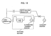
- FIG. 13 shows one example of a circuit diagram showing a manner of brushless excitation in the comparative example.
- Fig. 1 illustrates a first embodiment of the present invention.
- a rotating shaft 1 is connected to a turbine through a coupling 3.
- a sub-exciter 5 is mounted over the rotating shaft 1 on the side nearer to the turbine than a stator 2.
- An alternating-current (AC) exciter 4 is mounted over the rotating shaft 1 in its end region on the side opposite to the turbine.
- AC alternating-current
- Fig. 2 illustrates a second embodiment of the present invention.
- the sub-exciter 5 is mounted over the rotating shaft 1 between a turbine-side bearing 6 for supporting the rotating shaft 1 and the coupling 3. With such an arrangement, the length of an overhang required for mounting of the sub-exciter can be reduced.
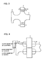
- Fig. 3 illustrates a third embodiment of the present invention.
- a turbogenerator having a coupling 3 that is co-cut from a rotating shaft 1 when a sub-exciter having a ring-shaped rotor 9 is mounted over the rotating shaft on the side near the turbine by shrink fitting, an inner diameter of the rotor 9 of the sub-exciter requires to be larger than an outer diameter of the coupling 3.
- a pedestal portion having a larger diameter than the coupling 3 is cut from the rotating shaft so that the ring-shaped rotor can be mounted in place by shrink fitting.
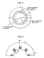
- Figs. 4 and 5 illustrate a fourth embodiment of the present invention. Because the rotor of the sub-exciter is mounted over the rotating shaft of the turbogenerator rotating at a high speed, an enlarged outer diameter increases a centrifugal force.
- a stator 7 of the sub-exciter 5, including the armature winding 8, is of a structure capable of being split in the circumferential direction and a magnetic pole 23 is directly mounted over the rotating shaft.
- the sub-exciter can be mounted even with the stator 7 having an inner diameter smaller than the outer diameter of the coupling 3.
- Fig. 4 is a view looking in the radial direction
- Fig. 5 is a view looking in the axial direction from the turbine side.
- Fig. 6 illustrates a fifth embodiment of the present invention.
- Fig. 6 shows a half of the divided stator in which armature windings 8a and 8b of the sub-exciter are wound over one of teeth 10 (or in halves of slots on both sides of each tooth) formed in a stator core 9 of the sub-exciter.
- Other armature windings accommodated in other slots are also wound in a similarly concentrated manner.
- the stator 7 of the sub-exciter can be split in the circumferential direction at any desired one of slots 11.
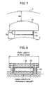
- Figs. 7 and 8 illustrate a sixth embodiment of the present invention.
- Fig. 7 is an axial sectional view of a magnetic pole of the sub-exciter provided in the turbogenerator of the present invention.
- the permanent magnet 13 is mounted between the rotating shaft 1 and a pole shoe 12 and is covered with a magnet cover 14 made of a nonmagnetic material so that the permanent magnet 13 is prevented from being dislodged and flying outward.
- the magnet cover 14 should be nonmagnetic to prevent establishment of a short-circuiting path of magnetic flux from the pole shoe 12 to the rotating shaft 1.
- a minimum air gap Ga (mm) between the stator 7 and the rotor of the sub-exciter is set not smaller than 5 mm so as to prevent generation of heat in the surface of the pole shoe 12 due to an eddy current losses.
- a distance Gp (mm) between the pole shoe 12 and the rotating shaft 1 and a thickness Gm (mm) of the permanent magnet 13 satisfy the relationships of 0.9 ⁇ Gp/Ga and 0.9 ⁇ Gm/Ga. With such settings, the magnetic flux can be prevented from leaking from the pole shoe 12 to the rotating shaft 1.
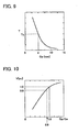
- Fig. 9 shows an analysis result representing the relationship between the air gap Ga and a permanent magnet temperature T.
- the irreversible thermal demagnetization temperature is about from 90°C to 220°C. Therefore, the permanent magnet can be used without causing thermal demagnetization by setting the air gap Ga to be not smaller than 5 mm.
- Fig. 10 shows an analysis result representing the relationship between Gp/Ga and an induced voltage V of the sub-exciter.
- Gp/Ga when Gp/Ga is smaller than 0.9, the induced voltage V is reduced due to a leakage of magnetic flux from the pole shoe to the rotating shaft.
- Gp/Ga By setting Gp/Ga to be not smaller than 0.9, a reduction of the induced voltage V can be avoided.
- Fig. 11 shows an analysis result representing the relationship between Gm/Ga and an induced voltage V of the sub-exciter.
- Fig. 11 by setting the magnet thickness so as to satisfy the relationship of 0.9 ⁇ Gm/Ga, a reduction of the induced voltage V can be avoided without forming a magnetic gap around the permanent magnet.
- Fig. 8 is a sectional view of the magnetic pole of the sub-exciter provided in the turbogenerator of the present invention, the view being taken along the radial direction.
- the pole shoe 12 has a longer axial length than the permanent magnet 13, and bolt holes are formed in portions of the pole shoe 12 axially extending with respect to the permanent magnet 13.
- the pole shoe 12 is fixed in place by fastening nonmagnetic bolts 15 into the bolt holes.
- the pole shoe 12 can be mounted in place by the bolts with no need of forming holes in the permanent magnet without impeding main magnetic flux in the pole shoe 12.
- nonmagnetic bolts it is possible to prevent establishment of a short-circuiting path of magnetic flux from the pole shoe 12 to the rotating shaft 1.
Landscapes
- Engineering & Computer Science (AREA)
- Mechanical Engineering (AREA)
- General Engineering & Computer Science (AREA)
- Chemical & Material Sciences (AREA)
- Combustion & Propulsion (AREA)
- Synchronous Machinery (AREA)
- Permanent Magnet Type Synchronous Machine (AREA)
- Connection Of Motors, Electrical Generators, Mechanical Devices, And The Like (AREA)
- Control Of Eletrric Generators (AREA)
Claims (5)
- Turbogénérateur comprenant :un rotor sur lequel est disposé un enroulement de champ (21) ;un aimant permanent (13) ;un générateur pour l'excitation en courant alternatif générant un courant avec un champ magnétique produit par ledit aimant permanent (13) ;un excitateur (4) destiné à fournir un courant à l'enroulement de champ (21) dudit rotor sur la base du courant généré par ledit générateur pour l'excitation en courant alternatif ; etune turbine destinée à produire une force motrice pour faire tourner ledit rotor,caractérisé en ce quel'aimant permanent (13) dudit générateur pour l'excitation en courant alternatif est disposé entre une pièce polaire (12) et un arbre de rotation (1) dudit rotor.
- Le turbogénérateur selon la revendication 1, dans lequel ladite pièce polaire (12) possède des parties se prolongeant sur une longueur supérieure à une longueur axiale dudit aimant permanent (13), des trous de boulons sont formés dans les parties de prolongement de ladite pièce polaire (12), et ladite pièce polaire (12) est fixée à l'arbre de rotation (1) dudit rotor par des boulons (15) fixés dans lesdits trous de boulons.
- Le turbogénérateur selon l'une des revendications 1 ou 2, dans lequel un espace minimum entre un stator dudit générateur pour l'excitation en courant alternatif et ledit rotor n'est pas inférieur à 5 mm.
- Le turbogénérateur selon les revendications 1 à 3, dans lequel, en supposant qu'un espace minimum entre un stator dudit générateur pour l'excitation en courant alternatif et ledit rotor est Ga et qu'une épaisseur dudit aimant permanent est Gm, la relation de 0.9 < Gm/Ga est satisfaite.
- Le turbogénérateur selon les revendications 1 à 4, dans lequel une partie dudit rotor dans laquelle est disposé ledit générateur pour l'excitation en courant alternatif présente un diamètre extérieur supérieur à un diamètre extérieur de l'autre partie dudit rotor.
Applications Claiming Priority (2)
| Application Number | Priority Date | Filing Date | Title |
|---|---|---|---|
| JP2004372481A JP4591075B2 (ja) | 2004-12-24 | 2004-12-24 | タービン発電機 |
| EP05017866A EP1679427B1 (fr) | 2004-12-24 | 2005-08-17 | Turbo-générateur |
Related Parent Applications (1)
| Application Number | Title | Priority Date | Filing Date |
|---|---|---|---|
| EP05017866.4 Division | 2005-08-17 |
Publications (2)
| Publication Number | Publication Date |
|---|---|
| EP2372106A1 EP2372106A1 (fr) | 2011-10-05 |
| EP2372106B1 true EP2372106B1 (fr) | 2012-11-21 |
Family
ID=36215531
Family Applications (2)
| Application Number | Title | Priority Date | Filing Date |
|---|---|---|---|
| EP11002470A Expired - Lifetime EP2372106B1 (fr) | 2004-12-24 | 2005-08-17 | Turbo-générateur |
| EP05017866A Expired - Lifetime EP1679427B1 (fr) | 2004-12-24 | 2005-08-17 | Turbo-générateur |
Family Applications After (1)
| Application Number | Title | Priority Date | Filing Date |
|---|---|---|---|
| EP05017866A Expired - Lifetime EP1679427B1 (fr) | 2004-12-24 | 2005-08-17 | Turbo-générateur |
Country Status (4)
| Country | Link |
|---|---|
| US (1) | US7732958B2 (fr) |
| EP (2) | EP2372106B1 (fr) |
| JP (1) | JP4591075B2 (fr) |
| CN (2) | CN100407556C (fr) |
Families Citing this family (9)
| Publication number | Priority date | Publication date | Assignee | Title |
|---|---|---|---|---|
| EP2528201A1 (fr) * | 2011-05-24 | 2012-11-28 | Alstom Technology Ltd | Procédé d'application d'un système de rétention au-dessus d'un coeur de rotor de machine électrique et ensemble de rotor |
| WO2013067605A2 (fr) * | 2011-11-09 | 2013-05-16 | Banjanovic Nijaz | Nouveau système excitateur pour générateurs synchrones classiques |
| US20130169074A1 (en) * | 2011-12-31 | 2013-07-04 | Sheikh Nayyer Hussain | Synchronous relcutance motor for conducting media |
| EP2704310B1 (fr) * | 2012-08-28 | 2019-02-13 | GE Renewable Technologies | Procédé pour le fonctionnement d'une telle machine électrique |
| US8963510B1 (en) * | 2013-08-23 | 2015-02-24 | Kohler Co. | Acyclic exciter for an alternator |
| KR102069734B1 (ko) | 2016-02-12 | 2020-01-28 | 지멘스 악티엔게젤샤프트 | 시동 모터를 갖는 가스 터빈 트레인 |
| CN108757351B (zh) * | 2018-03-29 | 2020-05-26 | 北京金风科创风电设备有限公司 | 直驱式风力发电机组 |
| CN109742898B (zh) * | 2018-12-28 | 2020-11-03 | 西安航天泵业有限公司 | 一种集成式全封闭低温液力发电装置 |
| CN111963319B (zh) * | 2020-09-02 | 2024-09-27 | 西北工业大学 | 微型涡喷发动机强磁耦合大功率发电系统 |
Family Cites Families (20)
| Publication number | Priority date | Publication date | Assignee | Title |
|---|---|---|---|---|
| US2189524A (en) * | 1936-04-03 | 1940-02-06 | Gen Motors Corp | Magneto rotor construction |
| FR1054581A (fr) * | 1951-04-17 | 1954-02-11 | Asea Ab | Génératrice pour la commande de régulateurs |
| US3052958A (en) * | 1957-05-02 | 1962-09-11 | Thompson Ramo Wooldridge Inc | Method of making a permanent magnet rotor |
| JPS4730081Y1 (fr) * | 1968-12-23 | 1972-09-08 | ||
| GB1414966A (en) * | 1971-10-25 | 1975-11-19 | Reyrolle Parsons Ltd | Dynamo-electric machines |
| JPS4947810A (fr) * | 1972-08-23 | 1974-05-09 | ||
| GB1523467A (en) * | 1975-11-06 | 1978-08-31 | Plessey Co Ltd | Rotary electric machines |
| JPS5921264A (ja) * | 1982-07-28 | 1984-02-03 | Toshiba Corp | ブラシレス同期電動機装置 |
| JPS61128799A (ja) * | 1984-11-28 | 1986-06-16 | Fuji Electric Co Ltd | ブラシレス同期機 |
| US4728840A (en) * | 1987-03-16 | 1988-03-01 | Westinghouse Electric Corp. | Water-cooled AC and DC motor-generator set on a common shaft with series cooling flow path |
| US4918343A (en) * | 1988-10-13 | 1990-04-17 | Kohler Co. | Brushless alternator |
| US5371426A (en) * | 1990-11-20 | 1994-12-06 | Seiko Epson Corporation | Rotor of brushless motor |
| JPH0529275A (ja) * | 1991-07-23 | 1993-02-05 | Kokusai Electric Co Ltd | プラズマエツチング方法及び装置 |
| US5587616A (en) * | 1993-05-04 | 1996-12-24 | Sundstrand Corporation | Rotor for a dynamoelectric machine having a one-piece rotation rectifier |
| US5994804A (en) * | 1998-12-07 | 1999-11-30 | Sundstrand Corporation | Air cooled dynamoelectric machine |
| US6285089B1 (en) * | 1999-11-24 | 2001-09-04 | Siemens Westinghouse Power Corporation | Induction static start for a turbine generator with a brushless exciter and associated methods |
| JP2003134764A (ja) * | 2001-10-22 | 2003-05-09 | Nishishiba Electric Co Ltd | ブラシレス回転電機 |
| US6768278B2 (en) * | 2002-08-06 | 2004-07-27 | Honeywell International, Inc. | Gas turbine engine starter generator with switchable exciter stator windings |
| US6906479B2 (en) * | 2002-08-06 | 2005-06-14 | Honeywell International, Inc. | Gas turbine engine starter generator with multiple windings on each exciter stator pole |
| US6791204B2 (en) * | 2002-09-20 | 2004-09-14 | Honeywell International Inc. | Torque generation for salient-pole synchronous machine for start-up of a prime mover |
-
2004
- 2004-12-24 JP JP2004372481A patent/JP4591075B2/ja not_active Expired - Lifetime
-
2005
- 2005-08-05 CN CN2005100891825A patent/CN100407556C/zh not_active Expired - Lifetime
- 2005-08-05 CN CNA2007101960982A patent/CN101170269A/zh active Pending
- 2005-08-17 EP EP11002470A patent/EP2372106B1/fr not_active Expired - Lifetime
- 2005-08-17 EP EP05017866A patent/EP1679427B1/fr not_active Expired - Lifetime
- 2005-08-19 US US11/206,767 patent/US7732958B2/en not_active Expired - Lifetime
Also Published As
| Publication number | Publication date |
|---|---|
| JP2006180644A (ja) | 2006-07-06 |
| CN100407556C (zh) | 2008-07-30 |
| JP4591075B2 (ja) | 2010-12-01 |
| EP1679427A2 (fr) | 2006-07-12 |
| EP1679427A3 (fr) | 2010-02-17 |
| EP1679427B1 (fr) | 2011-10-12 |
| CN101170269A (zh) | 2008-04-30 |
| US20060138881A1 (en) | 2006-06-29 |
| CN1794541A (zh) | 2006-06-28 |
| EP2372106A1 (fr) | 2011-10-05 |
| US7732958B2 (en) | 2010-06-08 |
Similar Documents
| Publication | Publication Date | Title |
|---|---|---|
| US20060131986A1 (en) | Axial gap permanent magnet reluctance motor and method | |
| CN110663158B (zh) | 用于交流电机的双磁相材料环 | |
| EP3416268B1 (fr) | Machine électrique à commutation de flux à trois phases avec aimants orientés perpendiculairement | |
| US6727631B2 (en) | Rotary electrical machine | |
| EP3648305A1 (fr) | Machine électrique ayant une conception de dent hybride | |
| JP2000156947A (ja) | 磁石式電動機及び発電機 | |
| US10992190B2 (en) | Self-exciting synchronous reluctance generators | |
| EP3410574B1 (fr) | Machines synchrones hybrides | |
| JP2000041367A (ja) | ハイブリッド励磁形同期機 | |
| GB2443032A (en) | Rotating machine operable as a generator and as a starter | |
| US20040232794A1 (en) | Method and radial gap machine for high strength undiffused brushless operation | |
| EP2372106B1 (fr) | Turbo-générateur | |
| US20040090134A1 (en) | Generator having a brushless excitor and power generating installation making use of the same | |
| CN114765392A (zh) | 具有容纳带的电机 | |
| US20240055916A1 (en) | Wound-field synchronous machines and control | |
| US20230361636A1 (en) | Electric machine having asymmetric magnet arrangement | |
| JP2010279127A (ja) | 磁気誘導子型回転機およびそれを用いたターボチャージャ | |
| KR102182353B1 (ko) | 회전 전기 기계 | |
| JP2010239862A (ja) | タービン発電機 | |
| Mbadiwe et al. | Comparative Study of PM Flux Switching and Surface Mounted PM Synchronous Machines for Direct-drive Vehicle Applications | |
| CN119678353A (zh) | 用于散热器风扇的无刷的电动马达 |
Legal Events
| Date | Code | Title | Description |
|---|---|---|---|
| PUAI | Public reference made under article 153(3) epc to a published international application that has entered the european phase |
Free format text: ORIGINAL CODE: 0009012 |
|
| 17P | Request for examination filed |
Effective date: 20110726 |
|
| AC | Divisional application: reference to earlier application |
Ref document number: 1679427 Country of ref document: EP Kind code of ref document: P |
|
| AK | Designated contracting states |
Kind code of ref document: A1 Designated state(s): DE FR GB |
|
| RIC1 | Information provided on ipc code assigned before grant |
Ipc: F02C 7/268 20060101ALI20120430BHEP Ipc: F01D 15/10 20060101AFI20120430BHEP Ipc: H02P 9/08 20060101ALI20120430BHEP |
|
| GRAP | Despatch of communication of intention to grant a patent |
Free format text: ORIGINAL CODE: EPIDOSNIGR1 |
|
| GRAS | Grant fee paid |
Free format text: ORIGINAL CODE: EPIDOSNIGR3 |
|
| GRAA | (expected) grant |
Free format text: ORIGINAL CODE: 0009210 |
|
| AC | Divisional application: reference to earlier application |
Ref document number: 1679427 Country of ref document: EP Kind code of ref document: P |
|
| AK | Designated contracting states |
Kind code of ref document: B1 Designated state(s): DE FR GB |
|
| REG | Reference to a national code |
Ref country code: GB Ref legal event code: FG4D |
|
| REG | Reference to a national code |
Ref country code: DE Ref legal event code: R096 Ref document number: 602005037145 Country of ref document: DE Effective date: 20130117 |
|
| PLBE | No opposition filed within time limit |
Free format text: ORIGINAL CODE: 0009261 |
|
| STAA | Information on the status of an ep patent application or granted ep patent |
Free format text: STATUS: NO OPPOSITION FILED WITHIN TIME LIMIT |
|
| 26N | No opposition filed |
Effective date: 20130822 |
|
| REG | Reference to a national code |
Ref country code: DE Ref legal event code: R097 Ref document number: 602005037145 Country of ref document: DE Effective date: 20130822 |
|
| REG | Reference to a national code |
Ref country code: DE Ref legal event code: R082 Ref document number: 602005037145 Country of ref document: DE Representative=s name: BEETZ & PARTNER PATENT- UND RECHTSANWAELTE, DE |
|
| REG | Reference to a national code |
Ref country code: DE Ref legal event code: R082 Ref document number: 602005037145 Country of ref document: DE Representative=s name: BEETZ & PARTNER PATENT- UND RECHTSANWAELTE, DE Effective date: 20140818 Ref country code: DE Ref legal event code: R081 Ref document number: 602005037145 Country of ref document: DE Owner name: MITSUBISHI HITACHI POWER SYSTEMS, LTD., YOKOHA, JP Free format text: FORMER OWNER: HITACHI, LTD., TOKYO, JP Effective date: 20140818 Ref country code: DE Ref legal event code: R082 Ref document number: 602005037145 Country of ref document: DE Representative=s name: BEETZ & PARTNER MBB PATENT- UND RECHTSANWAELTE, DE Effective date: 20140818 Ref country code: DE Ref legal event code: R082 Ref document number: 602005037145 Country of ref document: DE Representative=s name: BEETZ & PARTNER MBB, DE Effective date: 20140818 Ref country code: DE Ref legal event code: R082 Ref document number: 602005037145 Country of ref document: DE Representative=s name: BEETZ & PARTNER MBB PATENTANWAELTE, DE Effective date: 20140818 |
|
| REG | Reference to a national code |
Ref country code: FR Ref legal event code: TP Owner name: MITSUBISHI HITACHI POWER SYSTEMS, LTD., JP Effective date: 20141124 |
|
| REG | Reference to a national code |
Ref country code: GB Ref legal event code: 732E Free format text: REGISTERED BETWEEN 20150528 AND 20150603 |
|
| REG | Reference to a national code |
Ref country code: FR Ref legal event code: PLFP Year of fee payment: 12 |
|
| REG | Reference to a national code |
Ref country code: FR Ref legal event code: PLFP Year of fee payment: 13 |
|
| REG | Reference to a national code |
Ref country code: FR Ref legal event code: PLFP Year of fee payment: 14 |
|
| REG | Reference to a national code |
Ref country code: DE Ref legal event code: R081 Ref document number: 602005037145 Country of ref document: DE Owner name: MITSUBISHI HEAVY INDUSTRIES, LTD., JP Free format text: FORMER OWNER: MITSUBISHI HITACHI POWER SYSTEMS, LTD., YOKOHAMA-SHI, KANAGAWA, JP Ref country code: DE Ref legal event code: R081 Ref document number: 602005037145 Country of ref document: DE Owner name: MITSUBISHI GENERATOR CO., LTD., KOBE-SHI, JP Free format text: FORMER OWNER: MITSUBISHI HITACHI POWER SYSTEMS, LTD., YOKOHAMA-SHI, KANAGAWA, JP Ref country code: DE Ref legal event code: R082 Ref document number: 602005037145 Country of ref document: DE Representative=s name: BEETZ & PARTNER MBB PATENTANWAELTE, DE Ref country code: DE Ref legal event code: R081 Ref document number: 602005037145 Country of ref document: DE Owner name: MITSUBISHI POWER, LTD., JP Free format text: FORMER OWNER: MITSUBISHI HITACHI POWER SYSTEMS, LTD., YOKOHAMA-SHI, KANAGAWA, JP |
|
| REG | Reference to a national code |
Ref country code: DE Ref legal event code: R081 Ref document number: 602005037145 Country of ref document: DE Owner name: MITSUBISHI HEAVY INDUSTRIES, LTD., JP Free format text: FORMER OWNER: MITSUBISHI POWER, LTD., YOKOHAMA, JP Ref country code: DE Ref legal event code: R081 Ref document number: 602005037145 Country of ref document: DE Owner name: MITSUBISHI GENERATOR CO., LTD., KOBE-SHI, JP Free format text: FORMER OWNER: MITSUBISHI POWER, LTD., YOKOHAMA, JP |
|
| REG | Reference to a national code |
Ref country code: GB Ref legal event code: 732E Free format text: REGISTERED BETWEEN 20230907 AND 20230913 |
|
| PGFP | Annual fee paid to national office [announced via postgrant information from national office to epo] |
Ref country code: GB Payment date: 20240627 Year of fee payment: 20 |
|
| REG | Reference to a national code |
Ref country code: DE Ref legal event code: R081 Ref document number: 602005037145 Country of ref document: DE Owner name: MITSUBISHI GENERATOR CO., LTD., KOBE-SHI, JP Free format text: FORMER OWNER: MITSUBISHI HEAVY INDUSTRIES, LTD., TOKYO, JP |
|
| PGFP | Annual fee paid to national office [announced via postgrant information from national office to epo] |
Ref country code: DE Payment date: 20240702 Year of fee payment: 20 |
|
| PGFP | Annual fee paid to national office [announced via postgrant information from national office to epo] |
Ref country code: FR Payment date: 20240702 Year of fee payment: 20 |
|
| REG | Reference to a national code |
Ref country code: GB Ref legal event code: 732E Free format text: REGISTERED BETWEEN 20241107 AND 20241113 |
|
| REG | Reference to a national code |
Ref country code: DE Ref legal event code: R071 Ref document number: 602005037145 Country of ref document: DE |
|
| REG | Reference to a national code |
Ref country code: GB Ref legal event code: PE20 Expiry date: 20250816 |