EP2372260A2 - Procédé de chauffage d'eau en continu et système de chauffage d'eau - Google Patents
Procédé de chauffage d'eau en continu et système de chauffage d'eau Download PDFInfo
- Publication number
- EP2372260A2 EP2372260A2 EP11159320A EP11159320A EP2372260A2 EP 2372260 A2 EP2372260 A2 EP 2372260A2 EP 11159320 A EP11159320 A EP 11159320A EP 11159320 A EP11159320 A EP 11159320A EP 2372260 A2 EP2372260 A2 EP 2372260A2
- Authority
- EP
- European Patent Office
- Prior art keywords
- temperature
- water
- heating fluid
- outlet
- heat
- Prior art date
- Legal status (The legal status is an assumption and is not a legal conclusion. Google has not performed a legal analysis and makes no representation as to the accuracy of the status listed.)
- Granted
Links
- 238000010438 heat treatment Methods 0.000 title claims abstract description 96
- XLYOFNOQVPJJNP-UHFFFAOYSA-N water Substances O XLYOFNOQVPJJNP-UHFFFAOYSA-N 0.000 title claims abstract description 73
- 238000000034 method Methods 0.000 title claims abstract description 26
- 239000008236 heating water Substances 0.000 title claims description 7
- 239000012530 fluid Substances 0.000 claims abstract description 74
- 230000008859 change Effects 0.000 claims abstract description 19
- 230000001105 regulatory effect Effects 0.000 claims abstract description 6
- 230000001276 controlling effect Effects 0.000 claims description 7
- 230000008054 signal transmission Effects 0.000 claims description 3
- 235000020188 drinking water Nutrition 0.000 abstract description 22
- 239000003651 drinking water Substances 0.000 abstract description 22
- 230000000694 effects Effects 0.000 abstract description 5
- 230000006978 adaptation Effects 0.000 abstract description 2
- 238000012546 transfer Methods 0.000 description 10
- 238000002360 preparation method Methods 0.000 description 5
- 238000003860 storage Methods 0.000 description 5
- 230000007423 decrease Effects 0.000 description 4
- VNWKTOKETHGBQD-UHFFFAOYSA-N methane Chemical compound C VNWKTOKETHGBQD-UHFFFAOYSA-N 0.000 description 4
- 238000010079 rubber tapping Methods 0.000 description 4
- 238000009833 condensation Methods 0.000 description 3
- 230000005494 condensation Effects 0.000 description 3
- 239000000463 material Substances 0.000 description 3
- 239000008399 tap water Substances 0.000 description 3
- 235000020679 tap water Nutrition 0.000 description 3
- 230000033228 biological regulation Effects 0.000 description 2
- 230000001419 dependent effect Effects 0.000 description 2
- 239000000295 fuel oil Substances 0.000 description 2
- 238000004519 manufacturing process Methods 0.000 description 2
- 239000003345 natural gas Substances 0.000 description 2
- 230000008569 process Effects 0.000 description 2
- 230000004044 response Effects 0.000 description 2
- 230000008901 benefit Effects 0.000 description 1
- 238000007796 conventional method Methods 0.000 description 1
- 238000005260 corrosion Methods 0.000 description 1
- 230000007797 corrosion Effects 0.000 description 1
- 238000011161 development Methods 0.000 description 1
- 230000018109 developmental process Effects 0.000 description 1
- 238000010586 diagram Methods 0.000 description 1
- 230000035622 drinking Effects 0.000 description 1
- 230000007613 environmental effect Effects 0.000 description 1
- 239000002737 fuel gas Substances 0.000 description 1
- 230000006872 improvement Effects 0.000 description 1
- 238000013021 overheating Methods 0.000 description 1
- 230000009467 reduction Effects 0.000 description 1
- 230000032258 transport Effects 0.000 description 1
Images
Classifications
-
- F—MECHANICAL ENGINEERING; LIGHTING; HEATING; WEAPONS; BLASTING
- F24—HEATING; RANGES; VENTILATING
- F24D—DOMESTIC- OR SPACE-HEATING SYSTEMS, e.g. CENTRAL HEATING SYSTEMS; DOMESTIC HOT-WATER SUPPLY SYSTEMS; ELEMENTS OR COMPONENTS THEREFOR
- F24D19/00—Details
- F24D19/10—Arrangement or mounting of control or safety devices
- F24D19/1006—Arrangement or mounting of control or safety devices for water heating systems
- F24D19/1009—Arrangement or mounting of control or safety devices for water heating systems for central heating
-
- F—MECHANICAL ENGINEERING; LIGHTING; HEATING; WEAPONS; BLASTING
- F24—HEATING; RANGES; VENTILATING
- F24D—DOMESTIC- OR SPACE-HEATING SYSTEMS, e.g. CENTRAL HEATING SYSTEMS; DOMESTIC HOT-WATER SUPPLY SYSTEMS; ELEMENTS OR COMPONENTS THEREFOR
- F24D19/00—Details
- F24D19/10—Arrangement or mounting of control or safety devices
- F24D19/1006—Arrangement or mounting of control or safety devices for water heating systems
- F24D19/1066—Arrangement or mounting of control or safety devices for water heating systems for the combination of central heating and domestic hot water
- F24D19/1069—Arrangement or mounting of control or safety devices for water heating systems for the combination of central heating and domestic hot water regulation in function of the temperature of the domestic hot water
-
- F—MECHANICAL ENGINEERING; LIGHTING; HEATING; WEAPONS; BLASTING
- F24—HEATING; RANGES; VENTILATING
- F24H—FLUID HEATERS, e.g. WATER OR AIR HEATERS, HAVING HEAT-GENERATING MEANS, e.g. HEAT PUMPS, IN GENERAL
- F24H15/00—Control of fluid heaters
- F24H15/10—Control of fluid heaters characterised by the purpose of the control
- F24H15/174—Supplying heated water with desired temperature or desired range of temperature
-
- F—MECHANICAL ENGINEERING; LIGHTING; HEATING; WEAPONS; BLASTING
- F24—HEATING; RANGES; VENTILATING
- F24H—FLUID HEATERS, e.g. WATER OR AIR HEATERS, HAVING HEAT-GENERATING MEANS, e.g. HEAT PUMPS, IN GENERAL
- F24H15/00—Control of fluid heaters
- F24H15/20—Control of fluid heaters characterised by control inputs
- F24H15/212—Temperature of the water
- F24H15/219—Temperature of the water after heating
-
- F—MECHANICAL ENGINEERING; LIGHTING; HEATING; WEAPONS; BLASTING
- F24—HEATING; RANGES; VENTILATING
- F24H—FLUID HEATERS, e.g. WATER OR AIR HEATERS, HAVING HEAT-GENERATING MEANS, e.g. HEAT PUMPS, IN GENERAL
- F24H15/00—Control of fluid heaters
- F24H15/20—Control of fluid heaters characterised by control inputs
- F24H15/238—Flow rate
-
- F—MECHANICAL ENGINEERING; LIGHTING; HEATING; WEAPONS; BLASTING
- F24—HEATING; RANGES; VENTILATING
- F24H—FLUID HEATERS, e.g. WATER OR AIR HEATERS, HAVING HEAT-GENERATING MEANS, e.g. HEAT PUMPS, IN GENERAL
- F24H15/00—Control of fluid heaters
- F24H15/30—Control of fluid heaters characterised by control outputs; characterised by the components to be controlled
- F24H15/355—Control of heat-generating means in heaters
Definitions
- the invention relates to a method for heating water of variable volume flow according to the flow principle according to the preamble of claim 1, wherein a heat generator heated by a pump in a circulating heating fluid, the heating fluid heated in a run water, at least one in a waterway arranged sensor measures an outlet temperature T W and / or a volume flow V W of the water, and at least one arranged in a Walkerfluidweg sensor measures at least one Walkerfluidtemperatur T H of the heating fluid.
- the invention relates to a water heating system according to the flow principle according to the preamble of claim 7 with a heat generator, a heated by the heat generator heating fluid circuit, which is funded by a pump, heated by Schufluid Vietnamese water flow, at least one arranged in a waterway sensor for detecting an outlet temperature T. W , an inlet temperature T K and / or a volume flow V W of the water, and at least one arranged in a Walkerfluidweg sensor for detecting at least one Walkerfluidtemperatur T H of the heating fluid.
- Combination heaters can solve two heating tasks, such as hot water heating for room heating and domestic hot water for applications in the kitchen and sanitary area.
- a heater arranged in the heater (heat source) via a primary heat exchanger heats a circulating heating fluid (heating water), which is conveyed in a space heating mode by a pump (circulation pump) from the heater via flow and return lines to the rooms to be heated and there emits the heat, for example via space heaters (consumers, heat sink) to the room.
- a diverter valve directs the heating fluid to a secondary heat exchanger (eg, plate heat exchanger), often also located in the heater, where it transfers the heat to a flowing drinking water.
- a secondary heat exchanger eg, plate heat exchanger
- the drinking water flows usually under the pressure prevailing in the supply line by the secondary heat exchanger, is here by heat release on the part of Heating fluid heated and exits with a volume flow corresponding to an opening cross-section at a downstream tap fitting for use.
- the heat generator may be a burner fueled with fuel oil or natural gas, but also a heat generator operating with electrical energy.
- the heat generator can switch its heat output on and off and, as a rule, also modulate it between a minimum power different from zero and a maximum power (nominal power).
- a minimum power different from zero and a maximum power nominal power
- a maximum power nominal power
- drinking water of different volume flows can be heated.
- a set DHW temperature as well as minimum and maximum outflow temperatures can be set via a thermostat, a control unit and / or other components.
- the amount of a request made to the heat source heat demand to achieve the target hot water temperature results from the drinking water volume flow, the temperature of the incoming into the secondary heat exchanger cold drinking water (inlet temperature), the set temperature of expiring from the secondary heat exchanger warm drinking water (hot water, outlet setpoint temperature) and the efficiency chain for the heat transfer between heat generator and domestic hot water.
- a burner operated with fuel oil or natural gas heats a heating fluid via a corrosion-resistant primary heat exchanger.
- the humidity of the fuel gas produced by the burner condenses in the primary heat exchanger, whereby the energy yield is increased by the condensation heat (condensing effect).
- the primary heat exchanger must be well cooled, so it is a low Schufluid-return temperature required.
- the Schufluidvolumenstrom is unregulated, so not dependent on the drinking water volume flow, but constantly high, and he is, for example, at small drinking water flow rates significantly higher than the drinking water volume flow itself. This results, especially at low drinking water flow rates, relatively high Schufluid return temperatures, which, by their height, diminish the calorific value or completely destroy it.
- the heater can also be used to charge a domestic hot water tank with warm drinking water.
- the charging of a stratified charge accumulator is identical for the heating fluid circuit of a combination heater with the domestic hot water operation.
- the heat absorbed by the primary heat exchanger is released via the secondary heat exchanger to the drinking water to be heated.
- the cold water located in the lower part of the storage tank is conveyed through the secondary heat exchanger with a storage loading pump and heated by the heating fluid. After a drinking hot water tap, the temperature in the lower part of the store is just as cold as the inlet temperature of the drinking water in the combi appliance.
- the accumulator charge pump conveys the cold water from the lower part of the accumulator through the secondary heat exchanger into the upper part of the accumulator.
- the temperatures are the same as in the combination heater during direct tapping.
- a fixed set drinking water volume flow is conveyed by the storage loading pump through the secondary heat exchanger. This is usually set by a hydraulic throttle so that the heat generator is operated with a power just below the maximum power. This allows a quick recharge and a high degree of deployment.
- the main advantage of the stratified storage tank is that until just before the end of the charge, the cold storage water allows a low return temperature in the heating fluid circuit. This increases the efficiency of the charging process for condensing appliances.
- the setpoint temperature can be achieved in continuous operation and without cycles from the heat generator and the circulation pump.
- Changes in heat demand such as those resulting from a change in water volume flow, water inlet temperature, or setpoint temperature, must equally change the heat generator heat output.
- sudden changes in the heat demand can not be made immediately only be fulfilled with a time delay. This is due to the thermal inertia of the heat transfer system consisting of heat generator, primary heat exchanger, heating fluid circuit and secondary heat exchanger. The time delay can lead to overshoots and undershoots in the outlet temperature and the DHW comfort is negatively affected.
- Some heat generators have a predetermined, unchangeable rate of change (speed), with which the power modulation can be changed. Due to their mass and geometry as well as the specific heat capacity and the thermal conductivity of the material, the heat exchangers have a thermal inertia, which acts like a heat accumulator.
- the Schufluid Vietnameselauf has its thermal inertia due to its water volume and the mass and the material of the pipe elements used. Only two flow states are known for the heating fluid circuit according to the current state of the art for domestic hot water preparation: circulation at a nominal circulation volume (heating fluid volume) or nominal pump speed and zero circulation when the pump is switched off.
- Deviations of the outlet temperature from the outlet setpoint temperature may result due to changes in water volume flows or changed cold water inlet temperatures and have an effect on the heat generator as a changed heat requirement.
- An arranged in the outlet waterway temperature sensor detects the deviation, a temperature controller then causes an adjustment of the heat generator heat output to the new heat demand, which also changes the SchufluidVorlauftemperatur.
- the heat output transferred to the water is adjusted only with a time delay and the setpoint temperature is reached only with a time delay. For example, in the event of a sudden increase in the water volume flow, the heat generator heat output and the heating fluid flow temperature will increase and the heat transfer system will adjust to the new heat demand until the outlet temperature returns to the setpoint temperature after an initial undershooting of the setpoint temperature and / or minimum outlet temperature.
- the outlet temperature will initially exceed the setpoint temperature (and possibly even the maximum permissible outlet temperature in the short term) until the heat output and the heating fluid supply temperature are correspondingly reduced and have adapted the heat transfer system to the new heat requirement.
- the thermal inertia of the heat transfer system parameters of the temperature control underlying control algorithm 'it may also come to several overshoot and undershoot the outlet temperature to the setpoint temperature.
- the invention has for its object to provide a method for heating water by the flow principle and a water heating system, which provide the basis for a high utilization of the condensing effect in domestic hot water and react quickly and accurately to changing water flow rates.
- the method according to the invention for heating water of variable volume flow according to the continuous flow principle in which a heat generator heats a heating fluid conveyed by a pump in a circulation, the heating fluid heats a flow-guided water, at least one sensor arranged in a water flow has an outlet temperature T W and / or measures a volume flow V W of the water, and at least one arranged in a Walkerfluidweg sensor measures at least one Walkerfluidtemperatur T H of the heating fluid, aims to regulate the outlet temperature T W of the water to a predetermined set outlet temperature T W0 .
- the outlet temperature T W is controlled by means of a change of a modulatable and / or switchable flow rate V H of the heating fluid to the outlet target temperature T W0.
- the Schuffluidtemperatur T H is controlled by means of a change in a modulated and / or switchable heat capacity Q of the heat generator on heating fluid set temperature T H0.
- a suitable embodiment of the method is characterized in that if the outlet setpoint temperature T W0 is exceeded by the outlet temperature T W , as may result, for example, with a reduced tap water quantity V W or at an increased inlet temperature T K , the heating fluid volume flow V H is reduced is, and that when falling below the outlet target temperature T W0 , as may arise, for example, in an increased water tap V W or at a reduced inlet temperature T K , the Schufluidvolumenstrom V H is increased. With the reduced or increased Schufluidvolumenstrom V H is accompanied by a reduced or increased heat output to the tap water.
- a further suitable embodiment of the method is characterized in that when the heating fluid target temperature T H0 is exceeded by the heating fluid temperature T H , as it results, for example, with reduced heat output to the tapping water, the heat source heat output Q is reduced, and if the temperature falls below the Schufluid-target temperature T Ho , as it results, for example, with increased heat transfer to the tap water, the heat source heat output Q is increased.
- An embodiment of the method is characterized in that a heating fluid target temperature T HVo in the flow of Schufitmaschinenes by a constant difference amount is greater than the outlet target temperature T W0 of the water. This temperature increase ensures that even with finitely small secondary heat exchanger, the outlet setpoint temperature T W0 is reliably achieved.
- a particularly suitable embodiment of the method is characterized in that a heating fluid target temperature T HV0 in the flow of Schufites by a difference greater than the outlet target temperature T W0 of the water, wherein the difference amount of a water volume flow V W and / or from a Inlet temperature T K of the water results.
- This adapted temperature increase ensures that the heating fluid temperatures are as low as possible and thereby favor the condensation conditions for the utilization of the condensing effect in the primary heat exchanger.
- a further embodiment of the method is characterized in that, in the event of a deviation of the outlet temperature T W from the outlet setpoint temperature T W0 , in addition to the change in the heating fluid volume flow V H and before the heating fluid temperature T H deviates from the desired heating fluid temperature T H0 , also the heat generator heat output Q is changed.
- This serves to adapt the thermally inert heat transfer system at an early stage to the changing tapping conditions and to further reduce temperature overshoots and temperature undershoots.
- a module pump controller via a signal transmission path corresponding control signals to a module heat controller in a controller.
- the inventive method can be realized for example by two control modules, wherein a first module (“pump controller”) for controlling the Schufluidvolumenstroms and a second module (“heat controller”) is used to control the heat generator heat output.
- a first module for controlling the Schufluidvolumenstroms
- a second module is used to control the heat generator heat output.
- the heat controller to achieve the heating fluid target temperature changes the heat generator capacity and thus also the Schufluidvorlauftemperatur, this change also affects the drinking water outlet temperature.
- the deviation is compensated by the pump controller by means of a change in the Schufluidvolumenstroms.
- the pump regulator, the pump and the heating fluid circuit can react quickly and have no trouble balancing the slow change (thermal inertia) of the heating fluid flow temperature.
- the heat controller reduces the heat generator output until the heating fluid setpoint temperature has been reached, then the pump regulator must inevitably adapt to this change.
- the volume flow in the heating fluid circuit is automatically adjusted to the volume flow in the drinking water circuit. This results in a noticeable improvement in the heater efficiency, because with the decrease in the drinking water volume flow and the volume flow in the heating circuit decreases and thus the return temperature decreases.
- the inventive method is similar to changes in the water outlet temperature, which arise when the heat generator in the clock mode, automatically from. If the heating fluid supply temperature exceeds a maximum value, the heat generator must switch off until it drops below a minimum value again. Resulting temperature deviations of the DHW outlet temperature are compensated by the pump controller by changing the Schufluidvolumenstroms.
- the inventive method is particularly advantageous in heaters in which the primary heat exchanger has a large thermally inert mass, the secondary heat exchanger but a small mass.
- the primary heat exchanger has a large thermally inert mass
- the secondary heat exchanger but a small mass.
- This is the case, for example, with primary heat exchangers made of cast materials for condensing use the case.
- these have a plate heat exchanger as a secondary heat exchanger with low mass.
- the method solves or improves all fundamental problems that occur in domestic hot water.
- the various states of the system heat generator clocks, repeated taps, tap start at very high heat fluid temperature, etc.
- the failure of the interface to the pump controller does not lead to system failure, because the heat controller still regulates to a constant Schufluidvorlauftemperatur. This reduces the comfort for the customer, but the drinking water operation is still possible.
- the modulating pump operation improves not only the increase in the heater efficiency because of the almost delay-free response pump and the control quality of the process.
- the power consumption of the pump is lower because of the more frequent partial load operation.
- there will be no cost disadvantage since the modulating high-efficiency pumps will presumably be prescribed in the foreseeable future in the important European countries.
- the invention comprises a water heating system according to the continuous flow principle with a heat generator, a heated by the heat generator, pumped by a pump heating fluid, a heated by the heating fluid, conveyed in the flow, at least one arranged in a waterway sensor for detecting an outlet temperature T W , a Inlet temperature T K and / or a volumetric flow V W of the water, as well as at least one arranged in a Schufluidweg sensor for detecting at least one Schufluidtemperatur T H of the heating fluid, wherein for controlling the outlet temperature T W to a predetermined outlet target temperature T W0, the volume flow V H. the Schufluid Vietnameselaufs and the heat output Q of the heat generator can be modulated and / or switched.
- An embodiment of the water heating system is characterized by a control device connected to the heat generator, the pump and the sensors, comprising an input device for setting desired values and / or constants, a control module for controlling the pump and a control module for controlling the heat generator, wherein the control device influences the operation of the connected components and thus regulates the outlet temperature T W.
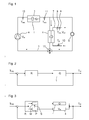
- Fig. 1 schematically shows a combination heater for room heating and domestic hot water.
- the heater comprises a heat generator 1 (heat source), a heated by the heat generator 1 via a primary heat exchanger 2 Schufluid Vietnameselauf 3, which is promoted (circulated) by a pump 4, and a connected to the heater heat consumer 5, for example, a space heater 5.
- the circulating heating fluid (Heat transfer medium) transports the heat from the heat source 1 to the heat consumer 5.
- the heater For domestic hot water, the heater comprises a working according to the flow principle water heating system with a heated by the heating fluid circuit 3 via a secondary heat exchanger 6 water flow 7, at least one arranged in a waterway 7 sensor 8, 9 10 for detecting an outlet temperature T W and / or an inlet temperature T K and / or a volumetric flow V W of the water, and at least one arranged in a Schufluidweg 3 sensor 11, 12 for detecting a flow temperature T HV and / or a remindl temperature T HR of the heating fluid.
- the heat output Q of the heat generator 1 and the volume flow V H of the heating fluid circuit 3 can be modulated and / or switched.
- the two heating tasks room heating and DHW heating are usually not fulfilled simultaneously, but individually.
- the heating fluid circuit 3 between the two heat consumers space heater 5 and secondary heat exchanger 6 is switched by means of a switching valve 13.
- Fig. 2 shows the schematic signal flow plan of a control circuit for domestic hot water production according to the input variable (setpoint) T W0 , the output (outlet temperature) T W , the controller R, the actuator (heat generator 1) and the manipulated variable Q.
- the heat generator 1 is the outlet temperature T W influenced.
- Fig. 3 shows the schematic signal flow plan of a control circuit for domestic hot water preparation according to the present invention with the input variable (setpoint) T W0 , the output (outlet temperature) T W , the controller R with module W (heat controller), module P (pump controller) and signal transmission path S between the two Controllers, the actuators (heat generator 1 and pump 4) and the manipulated variables Q and V H.
- the controller R with module W (heat controller), module P (pump controller) and signal transmission path S between the two Controllers, the actuators (heat generator 1 and pump 4) and the manipulated variables Q and V H.
- the outlet temperature T W is influenced.
Landscapes
- Engineering & Computer Science (AREA)
- Physics & Mathematics (AREA)
- Thermal Sciences (AREA)
- Chemical & Material Sciences (AREA)
- Combustion & Propulsion (AREA)
- Mechanical Engineering (AREA)
- General Engineering & Computer Science (AREA)
- Fluid Mechanics (AREA)
- Steam Or Hot-Water Central Heating Systems (AREA)
- Instantaneous Water Boilers, Portable Hot-Water Supply Apparatuses, And Control Of Portable Hot-Water Supply Apparatuses (AREA)
Applications Claiming Priority (1)
| Application Number | Priority Date | Filing Date | Title |
|---|---|---|---|
| DE102010013140A DE102010013140A1 (de) | 2010-03-27 | 2010-03-27 | Verfahren zur Erwärmung von Wasser nach dem Durchlaufprinzip und Wassererwärmungssystem |
Publications (3)
| Publication Number | Publication Date |
|---|---|
| EP2372260A2 true EP2372260A2 (fr) | 2011-10-05 |
| EP2372260A3 EP2372260A3 (fr) | 2014-01-22 |
| EP2372260B1 EP2372260B1 (fr) | 2016-05-11 |
Family
ID=44310249
Family Applications (1)
| Application Number | Title | Priority Date | Filing Date |
|---|---|---|---|
| EP11159320.8A Not-in-force EP2372260B1 (fr) | 2010-03-27 | 2011-03-23 | Procédé de chauffage d'eau en continu et système de chauffage d'eau |
Country Status (2)
| Country | Link |
|---|---|
| EP (1) | EP2372260B1 (fr) |
| DE (1) | DE102010013140A1 (fr) |
Cited By (2)
| Publication number | Priority date | Publication date | Assignee | Title |
|---|---|---|---|---|
| US10612795B2 (en) * | 2016-09-14 | 2020-04-07 | Lochinvar, Llc | Methods and system for demand-based control of a combination boiler |
| CN115104922A (zh) * | 2022-07-19 | 2022-09-27 | 芜湖艾尔达科技有限责任公司 | 一种饮水机及饮水机控制方法 |
Families Citing this family (5)
| Publication number | Priority date | Publication date | Assignee | Title |
|---|---|---|---|---|
| DE102018118432A1 (de) * | 2018-07-31 | 2020-02-06 | Oventrop Gmbh & Co. Kg | Verfahren zur Steuerung einer Heiz- und/oder Kühlanlage eines Bauwerkes |
| US12584327B2 (en) | 2021-06-03 | 2026-03-24 | Hayward Industries, Inc. | Modulating pool or spa heater systems and associated methods |
| US12222702B2 (en) | 2021-06-03 | 2025-02-11 | Hayward Industries, Inc. | Modulating pool or spa heater systems and associated methods |
| DE102021206320A1 (de) | 2021-06-21 | 2022-12-22 | Robert Bosch Gesellschaft mit beschränkter Haftung | Verfahren zum Bestimmen und/oder Optimieren einer Wärmeleistung eines Heizgeräts sowie Heizgerät und Steuergerät |
| WO2024112817A1 (fr) * | 2022-11-23 | 2024-05-30 | Hayward Industries, Inc. | Systèmes de chauffage de modulation pour une piscine ou un spa et procédés associés |
Family Cites Families (5)
| Publication number | Priority date | Publication date | Assignee | Title |
|---|---|---|---|---|
| DE1988343U (de) * | 1965-03-17 | 1968-06-27 | Junkers & Co | Gasbeheizter umlauf-wassererhitzer. |
| NL8503345A (nl) * | 1985-12-04 | 1987-07-01 | Nefit Nv | Inrichting voor het sturen van een warmwatervoorziening. |
| DE59306480D1 (de) * | 1992-02-18 | 1997-06-26 | Vaillant Joh Gmbh & Co | Verfahren zur Steuerung eines Kessels |
| DE19725951A1 (de) * | 1997-06-19 | 1999-01-21 | Bosch Gmbh Robert | Verfahren zur Brauchwasserbereitstellung in einem kombinierten System |
| DE19725952C2 (de) * | 1997-06-19 | 2001-09-13 | Bosch Gmbh Robert | Verfahren zur Brauchwasserbereitstellung in einem kombinierten System |
-
2010
- 2010-03-27 DE DE102010013140A patent/DE102010013140A1/de not_active Withdrawn
-
2011
- 2011-03-23 EP EP11159320.8A patent/EP2372260B1/fr not_active Not-in-force
Non-Patent Citations (1)
| Title |
|---|
| None |
Cited By (3)
| Publication number | Priority date | Publication date | Assignee | Title |
|---|---|---|---|---|
| US10612795B2 (en) * | 2016-09-14 | 2020-04-07 | Lochinvar, Llc | Methods and system for demand-based control of a combination boiler |
| US11828474B2 (en) | 2016-09-14 | 2023-11-28 | Lochinvar, Llc | Methods and system for demand-based control of a combination boiler |
| CN115104922A (zh) * | 2022-07-19 | 2022-09-27 | 芜湖艾尔达科技有限责任公司 | 一种饮水机及饮水机控制方法 |
Also Published As
| Publication number | Publication date |
|---|---|
| EP2372260A3 (fr) | 2014-01-22 |
| EP2372260B1 (fr) | 2016-05-11 |
| DE102010013140A1 (de) | 2011-09-29 |
Similar Documents
| Publication | Publication Date | Title |
|---|---|---|
| EP2372260B1 (fr) | Procédé de chauffage d'eau en continu et système de chauffage d'eau | |
| DE102008038617B4 (de) | Verfahren und Vorrichtung zur Wärmenutzung | |
| EP2187136A2 (fr) | Procédé de fonctionnement d'un système de transport d'énergie thermique sur un support fluide | |
| DE102011001223A1 (de) | Heizungsanlage sowie Betriebsverfahren und Steuereinrichtung für eine Heizungsanlage | |
| EP2372259B1 (fr) | Procédé de chauffage d'eau en continu et système de chauffage d'eau | |
| EP1170554B1 (fr) | Ensemble et procédé pour préparer de l'eau chaude sanitaire | |
| EP0892223B1 (fr) | Dispositif de commande et de régulation pour système de chauffage | |
| DE19859364A1 (de) | Wärmeversorgungsanlage mit Spitzenlastbegrenzung | |
| EP0807790B1 (fr) | Méthode et système pour préparer de l'eau chaude sanitaire | |
| DE102008009285B3 (de) | Schichtladespeichersystem und Verfahren zum Betreiben eines Schichtladespeichersystems | |
| EP3800403B1 (fr) | Procédé de fonctionnement d'un dispositif de chauffage, dispositif de chauffage | |
| DE10329565B4 (de) | Verfahren und Einrichtung zur Einstellung der aus dem Fernwärmenetz bezogenen Wärmemenge auf den wirklichen Bedarfsfall einer Hausanschlußstation | |
| EP1310736B1 (fr) | Régulateur et méthode de régulation pour un brûleur | |
| EP3385624A1 (fr) | Procédé de fonctionnement d'une installation de préparation d'eau sanitaire ou de chauffage, dispositif de commande et/ou de réglage pour une installation de préparation d'eau sanitaire et de chauffage et installation de préparation d'eau sanitaire | |
| EP0880659A1 (fr) | Regulateur solaire a effet modulateur | |
| EP1792125B1 (fr) | Dispositif de preparation d'eau industrielle | |
| AT400626B (de) | Heizungsanlage | |
| EP2492602A1 (fr) | Appareil et procédé pour optimiser le fonctionnement d'une chaudière pour chauffer l'eau | |
| DE102013012724A1 (de) | Vorrichtung zur Erwärmung von Heizwasser für eine Warmwasserbereitung | |
| AT411632B (de) | Verfahren zum regeln der entnahmetemperatur von brauchwasser | |
| DE3410316A1 (de) | Mehrkessel-heizungsanlage fuer fluessige waermetraegermedien | |
| EP4481280B1 (fr) | Installation de chauffage, procédé de fonctionnement d'une installation de chauffage et programme informatique | |
| EP0579933A1 (fr) | Procédé pour le chauffage d'eau sanitaire et chauffé-eau pour la mise en oeuvre du procédé | |
| DE10251336A1 (de) | Trinkwassererwärmer | |
| EP0936413B1 (fr) | Installation d'eau chaude avec régulateur pour la température d'eau |
Legal Events
| Date | Code | Title | Description |
|---|---|---|---|
| PUAI | Public reference made under article 153(3) epc to a published international application that has entered the european phase |
Free format text: ORIGINAL CODE: 0009012 |
|
| AK | Designated contracting states |
Kind code of ref document: A2 Designated state(s): AL AT BE BG CH CY CZ DE DK EE ES FI FR GB GR HR HU IE IS IT LI LT LU LV MC MK MT NL NO PL PT RO RS SE SI SK SM TR |
|
| AX | Request for extension of the european patent |
Extension state: BA ME |
|
| PUAL | Search report despatched |
Free format text: ORIGINAL CODE: 0009013 |
|
| AK | Designated contracting states |
Kind code of ref document: A3 Designated state(s): AL AT BE BG CH CY CZ DE DK EE ES FI FR GB GR HR HU IE IS IT LI LT LU LV MC MK MT NL NO PL PT RO RS SE SI SK SM TR |
|
| AX | Request for extension of the european patent |
Extension state: BA ME |
|
| RIC1 | Information provided on ipc code assigned before grant |
Ipc: F24D 19/10 20060101AFI20131217BHEP |
|
| 17P | Request for examination filed |
Effective date: 20140722 |
|
| RBV | Designated contracting states (corrected) |
Designated state(s): AL AT BE BG CH CY CZ DE DK EE ES FI FR GB GR HR HU IE IS IT LI LT LU LV MC MK MT NL NO PL PT RO RS SE SI SK SM TR |
|
| 17Q | First examination report despatched |
Effective date: 20141212 |
|
| GRAP | Despatch of communication of intention to grant a patent |
Free format text: ORIGINAL CODE: EPIDOSNIGR1 |
|
| INTG | Intention to grant announced |
Effective date: 20160119 |
|
| GRAS | Grant fee paid |
Free format text: ORIGINAL CODE: EPIDOSNIGR3 |
|
| GRAA | (expected) grant |
Free format text: ORIGINAL CODE: 0009210 |
|
| AK | Designated contracting states |
Kind code of ref document: B1 Designated state(s): AL AT BE BG CH CY CZ DE DK EE ES FI FR GB GR HR HU IE IS IT LI LT LU LV MC MK MT NL NO PL PT RO RS SE SI SK SM TR |
|
| REG | Reference to a national code |
Ref country code: GB Ref legal event code: FG4D Free format text: NOT ENGLISH |
|
| REG | Reference to a national code |
Ref country code: CH Ref legal event code: EP |
|
| REG | Reference to a national code |
Ref country code: AT Ref legal event code: REF Ref document number: 798971 Country of ref document: AT Kind code of ref document: T Effective date: 20160515 |
|
| REG | Reference to a national code |
Ref country code: IE Ref legal event code: FG4D Free format text: LANGUAGE OF EP DOCUMENT: GERMAN |
|
| REG | Reference to a national code |
Ref country code: DE Ref legal event code: R096 Ref document number: 502011009692 Country of ref document: DE |
|
| REG | Reference to a national code |
Ref country code: NL Ref legal event code: FP |
|
| REG | Reference to a national code |
Ref country code: LT Ref legal event code: MG4D |
|
| PG25 | Lapsed in a contracting state [announced via postgrant information from national office to epo] |
Ref country code: FI Free format text: LAPSE BECAUSE OF FAILURE TO SUBMIT A TRANSLATION OF THE DESCRIPTION OR TO PAY THE FEE WITHIN THE PRESCRIBED TIME-LIMIT Effective date: 20160511 Ref country code: LT Free format text: LAPSE BECAUSE OF FAILURE TO SUBMIT A TRANSLATION OF THE DESCRIPTION OR TO PAY THE FEE WITHIN THE PRESCRIBED TIME-LIMIT Effective date: 20160511 Ref country code: NO Free format text: LAPSE BECAUSE OF FAILURE TO SUBMIT A TRANSLATION OF THE DESCRIPTION OR TO PAY THE FEE WITHIN THE PRESCRIBED TIME-LIMIT Effective date: 20160811 |
|
| PG25 | Lapsed in a contracting state [announced via postgrant information from national office to epo] |
Ref country code: SE Free format text: LAPSE BECAUSE OF FAILURE TO SUBMIT A TRANSLATION OF THE DESCRIPTION OR TO PAY THE FEE WITHIN THE PRESCRIBED TIME-LIMIT Effective date: 20160511 Ref country code: LV Free format text: LAPSE BECAUSE OF FAILURE TO SUBMIT A TRANSLATION OF THE DESCRIPTION OR TO PAY THE FEE WITHIN THE PRESCRIBED TIME-LIMIT Effective date: 20160511 Ref country code: GR Free format text: LAPSE BECAUSE OF FAILURE TO SUBMIT A TRANSLATION OF THE DESCRIPTION OR TO PAY THE FEE WITHIN THE PRESCRIBED TIME-LIMIT Effective date: 20160812 Ref country code: PT Free format text: LAPSE BECAUSE OF FAILURE TO SUBMIT A TRANSLATION OF THE DESCRIPTION OR TO PAY THE FEE WITHIN THE PRESCRIBED TIME-LIMIT Effective date: 20160912 Ref country code: ES Free format text: LAPSE BECAUSE OF FAILURE TO SUBMIT A TRANSLATION OF THE DESCRIPTION OR TO PAY THE FEE WITHIN THE PRESCRIBED TIME-LIMIT Effective date: 20160511 Ref country code: HR Free format text: LAPSE BECAUSE OF FAILURE TO SUBMIT A TRANSLATION OF THE DESCRIPTION OR TO PAY THE FEE WITHIN THE PRESCRIBED TIME-LIMIT Effective date: 20160511 Ref country code: RS Free format text: LAPSE BECAUSE OF FAILURE TO SUBMIT A TRANSLATION OF THE DESCRIPTION OR TO PAY THE FEE WITHIN THE PRESCRIBED TIME-LIMIT Effective date: 20160511 |
|
| PG25 | Lapsed in a contracting state [announced via postgrant information from national office to epo] |
Ref country code: IT Free format text: LAPSE BECAUSE OF FAILURE TO SUBMIT A TRANSLATION OF THE DESCRIPTION OR TO PAY THE FEE WITHIN THE PRESCRIBED TIME-LIMIT Effective date: 20160511 |
|
| PG25 | Lapsed in a contracting state [announced via postgrant information from national office to epo] |
Ref country code: RO Free format text: LAPSE BECAUSE OF FAILURE TO SUBMIT A TRANSLATION OF THE DESCRIPTION OR TO PAY THE FEE WITHIN THE PRESCRIBED TIME-LIMIT Effective date: 20160511 Ref country code: SK Free format text: LAPSE BECAUSE OF FAILURE TO SUBMIT A TRANSLATION OF THE DESCRIPTION OR TO PAY THE FEE WITHIN THE PRESCRIBED TIME-LIMIT Effective date: 20160511 Ref country code: CZ Free format text: LAPSE BECAUSE OF FAILURE TO SUBMIT A TRANSLATION OF THE DESCRIPTION OR TO PAY THE FEE WITHIN THE PRESCRIBED TIME-LIMIT Effective date: 20160511 Ref country code: DK Free format text: LAPSE BECAUSE OF FAILURE TO SUBMIT A TRANSLATION OF THE DESCRIPTION OR TO PAY THE FEE WITHIN THE PRESCRIBED TIME-LIMIT Effective date: 20160511 Ref country code: EE Free format text: LAPSE BECAUSE OF FAILURE TO SUBMIT A TRANSLATION OF THE DESCRIPTION OR TO PAY THE FEE WITHIN THE PRESCRIBED TIME-LIMIT Effective date: 20160511 |
|
| REG | Reference to a national code |
Ref country code: DE Ref legal event code: R097 Ref document number: 502011009692 Country of ref document: DE |
|
| PG25 | Lapsed in a contracting state [announced via postgrant information from national office to epo] |
Ref country code: PL Free format text: LAPSE BECAUSE OF FAILURE TO SUBMIT A TRANSLATION OF THE DESCRIPTION OR TO PAY THE FEE WITHIN THE PRESCRIBED TIME-LIMIT Effective date: 20160511 Ref country code: SM Free format text: LAPSE BECAUSE OF FAILURE TO SUBMIT A TRANSLATION OF THE DESCRIPTION OR TO PAY THE FEE WITHIN THE PRESCRIBED TIME-LIMIT Effective date: 20160511 |
|
| PLBE | No opposition filed within time limit |
Free format text: ORIGINAL CODE: 0009261 |
|
| STAA | Information on the status of an ep patent application or granted ep patent |
Free format text: STATUS: NO OPPOSITION FILED WITHIN TIME LIMIT |
|
| 26N | No opposition filed |
Effective date: 20170214 |
|
| PG25 | Lapsed in a contracting state [announced via postgrant information from national office to epo] |
Ref country code: SI Free format text: LAPSE BECAUSE OF FAILURE TO SUBMIT A TRANSLATION OF THE DESCRIPTION OR TO PAY THE FEE WITHIN THE PRESCRIBED TIME-LIMIT Effective date: 20160511 |
|
| PG25 | Lapsed in a contracting state [announced via postgrant information from national office to epo] |
Ref country code: MC Free format text: LAPSE BECAUSE OF FAILURE TO SUBMIT A TRANSLATION OF THE DESCRIPTION OR TO PAY THE FEE WITHIN THE PRESCRIBED TIME-LIMIT Effective date: 20160511 |
|
| REG | Reference to a national code |
Ref country code: IE Ref legal event code: MM4A |
|
| REG | Reference to a national code |
Ref country code: FR Ref legal event code: ST Effective date: 20171130 |
|
| PG25 | Lapsed in a contracting state [announced via postgrant information from national office to epo] |
Ref country code: FR Free format text: LAPSE BECAUSE OF NON-PAYMENT OF DUE FEES Effective date: 20170331 Ref country code: LU Free format text: LAPSE BECAUSE OF NON-PAYMENT OF DUE FEES Effective date: 20170323 |
|
| PG25 | Lapsed in a contracting state [announced via postgrant information from national office to epo] |
Ref country code: IE Free format text: LAPSE BECAUSE OF NON-PAYMENT OF DUE FEES Effective date: 20170323 |
|
| REG | Reference to a national code |
Ref country code: BE Ref legal event code: MM Effective date: 20170331 |
|
| PG25 | Lapsed in a contracting state [announced via postgrant information from national office to epo] |
Ref country code: BE Free format text: LAPSE BECAUSE OF NON-PAYMENT OF DUE FEES Effective date: 20170331 |
|
| PG25 | Lapsed in a contracting state [announced via postgrant information from national office to epo] |
Ref country code: MT Free format text: LAPSE BECAUSE OF FAILURE TO SUBMIT A TRANSLATION OF THE DESCRIPTION OR TO PAY THE FEE WITHIN THE PRESCRIBED TIME-LIMIT Effective date: 20160511 |
|
| PG25 | Lapsed in a contracting state [announced via postgrant information from national office to epo] |
Ref country code: AL Free format text: LAPSE BECAUSE OF FAILURE TO SUBMIT A TRANSLATION OF THE DESCRIPTION OR TO PAY THE FEE WITHIN THE PRESCRIBED TIME-LIMIT Effective date: 20160511 |
|
| PG25 | Lapsed in a contracting state [announced via postgrant information from national office to epo] |
Ref country code: HU Free format text: LAPSE BECAUSE OF FAILURE TO SUBMIT A TRANSLATION OF THE DESCRIPTION OR TO PAY THE FEE WITHIN THE PRESCRIBED TIME-LIMIT; INVALID AB INITIO Effective date: 20110323 |
|
| PG25 | Lapsed in a contracting state [announced via postgrant information from national office to epo] |
Ref country code: BG Free format text: LAPSE BECAUSE OF FAILURE TO SUBMIT A TRANSLATION OF THE DESCRIPTION OR TO PAY THE FEE WITHIN THE PRESCRIBED TIME-LIMIT Effective date: 20160511 |
|
| PG25 | Lapsed in a contracting state [announced via postgrant information from national office to epo] |
Ref country code: CY Free format text: LAPSE BECAUSE OF NON-PAYMENT OF DUE FEES Effective date: 20160511 |
|
| PG25 | Lapsed in a contracting state [announced via postgrant information from national office to epo] |
Ref country code: MK Free format text: LAPSE BECAUSE OF FAILURE TO SUBMIT A TRANSLATION OF THE DESCRIPTION OR TO PAY THE FEE WITHIN THE PRESCRIBED TIME-LIMIT Effective date: 20160511 |
|
| PG25 | Lapsed in a contracting state [announced via postgrant information from national office to epo] |
Ref country code: TR Free format text: LAPSE BECAUSE OF FAILURE TO SUBMIT A TRANSLATION OF THE DESCRIPTION OR TO PAY THE FEE WITHIN THE PRESCRIBED TIME-LIMIT Effective date: 20160511 |
|
| PGFP | Annual fee paid to national office [announced via postgrant information from national office to epo] |
Ref country code: AT Payment date: 20200319 Year of fee payment: 10 |
|
| PGFP | Annual fee paid to national office [announced via postgrant information from national office to epo] |
Ref country code: CH Payment date: 20200325 Year of fee payment: 10 |
|
| PG25 | Lapsed in a contracting state [announced via postgrant information from national office to epo] |
Ref country code: IS Free format text: LAPSE BECAUSE OF FAILURE TO SUBMIT A TRANSLATION OF THE DESCRIPTION OR TO PAY THE FEE WITHIN THE PRESCRIBED TIME-LIMIT Effective date: 20160911 |
|
| REG | Reference to a national code |
Ref country code: CH Ref legal event code: PL |
|
| REG | Reference to a national code |
Ref country code: AT Ref legal event code: MM01 Ref document number: 798971 Country of ref document: AT Kind code of ref document: T Effective date: 20210323 |
|
| PG25 | Lapsed in a contracting state [announced via postgrant information from national office to epo] |
Ref country code: LI Free format text: LAPSE BECAUSE OF NON-PAYMENT OF DUE FEES Effective date: 20210331 Ref country code: CH Free format text: LAPSE BECAUSE OF NON-PAYMENT OF DUE FEES Effective date: 20210331 Ref country code: AT Free format text: LAPSE BECAUSE OF NON-PAYMENT OF DUE FEES Effective date: 20210323 |
|
| PGFP | Annual fee paid to national office [announced via postgrant information from national office to epo] |
Ref country code: DE Payment date: 20220525 Year of fee payment: 12 |
|
| PGFP | Annual fee paid to national office [announced via postgrant information from national office to epo] |
Ref country code: GB Payment date: 20230323 Year of fee payment: 13 |
|
| PGFP | Annual fee paid to national office [announced via postgrant information from national office to epo] |
Ref country code: NL Payment date: 20230322 Year of fee payment: 13 |
|
| REG | Reference to a national code |
Ref country code: DE Ref legal event code: R119 Ref document number: 502011009692 Country of ref document: DE |
|
| PG25 | Lapsed in a contracting state [announced via postgrant information from national office to epo] |
Ref country code: DE Free format text: LAPSE BECAUSE OF NON-PAYMENT OF DUE FEES Effective date: 20231003 |
|
| REG | Reference to a national code |
Ref country code: NL Ref legal event code: MM Effective date: 20240401 |
|
| GBPC | Gb: european patent ceased through non-payment of renewal fee |
Effective date: 20240323 |
|
| PG25 | Lapsed in a contracting state [announced via postgrant information from national office to epo] |
Ref country code: NL Free format text: LAPSE BECAUSE OF NON-PAYMENT OF DUE FEES Effective date: 20240401 |
|
| PG25 | Lapsed in a contracting state [announced via postgrant information from national office to epo] |
Ref country code: NL Free format text: LAPSE BECAUSE OF NON-PAYMENT OF DUE FEES Effective date: 20240401 |
|
| PG25 | Lapsed in a contracting state [announced via postgrant information from national office to epo] |
Ref country code: GB Free format text: LAPSE BECAUSE OF NON-PAYMENT OF DUE FEES Effective date: 20240323 |
|
| PG25 | Lapsed in a contracting state [announced via postgrant information from national office to epo] |
Ref country code: GB Free format text: LAPSE BECAUSE OF NON-PAYMENT OF DUE FEES Effective date: 20240323 |