EP2372281B1 - Four destiné au traitement thermique d'une multitude d'objets - Google Patents
Four destiné au traitement thermique d'une multitude d'objets Download PDFInfo
- Publication number
- EP2372281B1 EP2372281B1 EP10157826.8A EP10157826A EP2372281B1 EP 2372281 B1 EP2372281 B1 EP 2372281B1 EP 10157826 A EP10157826 A EP 10157826A EP 2372281 B1 EP2372281 B1 EP 2372281B1
- Authority
- EP
- European Patent Office
- Prior art keywords
- heating chamber
- oven
- oven according
- burner chambers
- burner
- Prior art date
- Legal status (The legal status is an assumption and is not a legal conclusion. Google has not performed a legal analysis and makes no representation as to the accuracy of the status listed.)
- Active
Links
Images




Classifications
-
- F—MECHANICAL ENGINEERING; LIGHTING; HEATING; WEAPONS; BLASTING
- F27—FURNACES; KILNS; OVENS; RETORTS
- F27B—FURNACES, KILNS, OVENS OR RETORTS IN GENERAL; OPEN SINTERING OR LIKE APPARATUS
- F27B17/00—Furnaces of a kind not covered by any of groups F27B1/00 - F27B15/00
- F27B17/0016—Chamber type furnaces
- F27B17/0041—Chamber type furnaces specially adapted for burning bricks or pottery
- F27B17/005—Chamber type furnaces specially adapted for burning bricks or pottery with cylindrical chambers
-
- F—MECHANICAL ENGINEERING; LIGHTING; HEATING; WEAPONS; BLASTING
- F27—FURNACES; KILNS; OVENS; RETORTS
- F27B—FURNACES, KILNS, OVENS OR RETORTS IN GENERAL; OPEN SINTERING OR LIKE APPARATUS
- F27B5/00—Muffle furnaces; Retort furnaces; Other furnaces in which the charge is held completely isolated
- F27B5/02—Muffle furnaces; Retort furnaces; Other furnaces in which the charge is held completely isolated of multiple-chamber type
-
- F—MECHANICAL ENGINEERING; LIGHTING; HEATING; WEAPONS; BLASTING
- F27—FURNACES; KILNS; OVENS; RETORTS
- F27B—FURNACES, KILNS, OVENS OR RETORTS IN GENERAL; OPEN SINTERING OR LIKE APPARATUS
- F27B5/00—Muffle furnaces; Retort furnaces; Other furnaces in which the charge is held completely isolated
- F27B5/06—Details, accessories or equipment specially adapted for furnaces of these types
- F27B5/08—Arrangements of linings
-
- F—MECHANICAL ENGINEERING; LIGHTING; HEATING; WEAPONS; BLASTING
- F27—FURNACES; KILNS; OVENS; RETORTS
- F27B—FURNACES, KILNS, OVENS OR RETORTS IN GENERAL; OPEN SINTERING OR LIKE APPARATUS
- F27B7/00—Rotary-drum furnaces, i.e. horizontal or slightly inclined
- F27B7/20—Details, accessories or equipment specially adapted for rotary-drum furnaces
- F27B7/22—Rotary drums; Supports therefor
Definitions
- the invention relates to a furnace for heat treatment of a variety of articles according to the preamble of claim 1. Furthermore, the invention relates to a furnace with a plurality of ovens.
- the heat treatment of grinding wheels takes several hours at temperatures above 200 ° C. Such a heat treatment causes high energy consumption since not only the grinding wheels but also the parts of the furnace absorb heat during heating. Most of the furnace parts are relatively heavy in the heated area of the furnace and have a high heat capacity.
- the oven has a vertical combustion chamber, which is equipped from below. Also, this oven has a relatively high energy consumption due to its structural design.
- the furnace comprises a support frame, which is formed as a three-dimensional frame, the heating chamber and the combustion chambers are arranged in the support frame, the support frame is provided for supporting the heating chamber and the combustion chambers, and the support frame of the heating chamber and the Combustion chambers is thermally decoupled, wherein the heating chamber and the combustion chambers are attached at least indirectly via a plurality of thermal insulation elements on the support frame.
- the essence of the invention lies in the fact that the supporting function in the furnace is taken over exclusively by the support frame.
- the heating chamber and the combustion chambers can be designed to be particularly thin-walled. This causes a low heat capacity of the heating chamber and the combustion chambers, so that the heating chamber and the combustion chambers absorb relatively little heat during operation, resulting in a significant energy saving.
- the at least one heating element can be arranged within the heating chamber and / or the heating chamber upstream and / or downstream. Alternatively or additionally, the heating element or elements can also be arranged in the combustion chambers or in the region of the covering hoods.
- the support framework is thermally decoupled from the heating chamber and from the combustion chambers. This leads to a further significant energy savings, since greatly reduced thermal bridges exist between the support frame on the one hand and the heating chamber and the combustion chambers on the other.
- the heating chamber and the combustion chambers are attached at least indirectly via a plurality of thermal insulation elements on the support frame.
- the thermal insulation elements are made of a high temperature insulating plastic.
- the walls of the heating chamber and / or the combustion chambers are at least partially provided with a thermal insulating material. As a result, a heat transfer from the heating chamber and the combustion chambers to the environment is prevented or at least significantly reduced.
- the heating chamber and the combustion chambers can be made in lightweight construction.
- the lightweight construction causes a particularly low heat capacity and thus a low heat absorption of the heating chamber and the combustion chambers. This results in a further substantial energy saving.
- the oven is provided for the heat treatment of disc-shaped objects, in particular grinding wheels.
- the grinding wheels are stacked in the combustion chambers.
- the cross section of the combustion chambers is adapted to the contour of the grinding wheels.
- the oven has a plurality of mandrels for stacking the disc-shaped objects.
- the mandrels are arranged one above the other in the vertical combustion chambers or side by side in the horizontal combustion chambers or introduced.
- a predetermined amount of grinding wheels can already be assembled outside the furnace with the mandrel.
- the mandrels can be introduced into the combustion chambers of the furnace "in packages" with the grinding wheels.
- the mandrels are made in lightweight construction.
- the mandrels have a particularly low heat capacity and thus a low heat absorption. This also contributes to energy savings.
- the heating element is arranged in an upper region of the vertical heating chamber.
- the heating element of the heating chamber can be upstream or downstream.
- the heating element is designed as an electrical heating element.
- all kinds of heating such as steam, oil, gas, thermal oil carriers, etc. are possible.
- the geometric shape of the combustion chambers can be adapted to the geometric shape of the objects, so that the distance between the objects and the walls of the combustion chambers is uniform. It can be formed between the objects and the walls of the combustion chambers at least one air duct with a uniform cross-section. As a result, less air masses for the required heat exchange must be moved.
- the blower can be made relatively small, which also causes an energy saving.
- the invention relates to a furnace with a plurality of ovens described above.
- the ovens are arranged side by side and coupled to each other by means of hot air ducts and cold air ducts, so that a direct or indirect heat exchange between cooling and heating ovens is made possible. Again, this is a major contribution to saving energy.
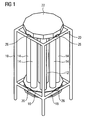
- FIG. 1 Figure 3 is a perspective view of a furnace according to a preferred embodiment of the invention.
- the oven is intended for heat treating a variety of items.
- the oven comprises a support frame 10, which is formed as a three-dimensional frame.
- the support frame 10 is substantially in the form of a cage.
- the oven further includes a heating chamber 12 located within the support 10 in the center thereof.
- the heating chamber 12 is elongated and arranged vertically. In this example, the heating chamber 12 has a round cross section.
- the combustion chambers 14 are also elongated and arranged vertically. In this example, eight combustors 14 are evenly distributed around the heating chamber 12 around.
- the combustion chambers 14 have a round cross-section.
- a base plate 16 At the lower ends of the heating chamber 12 and the combustion chambers 14 is a base plate 16.
- the base plate 16 is fixed to a lower horizontal frame 18 of the support frame 10. Between the base plate 16 and the lower horizontal frame 18 are thermal insulation elements 26th
- the thermal insulating members 26 are made of a material having low thermal conductivity.
- the base plate 16 is thus thermally decoupled from the lower horizontal frame 18.
- the thermal insulation elements 26 are made of a high temperature insulating plastic.
- the upper ends of the heating chamber 12 and the combustion chambers 14 are covered by a cover 22.
- the cover 22 is attached to an upper horizontal frame 20 of the support frame 10. Between the cover 22 and the upper horizontal frame 20 are also thermal insulation elements 26, so that the cover 22 is thermally decoupled from the upper horizontal frame 20.
- the upper ends of the heating chamber 12 and the combustion chambers 14 are interconnected.
- a heating element 28 In this embodiment, this is an electric heating element, which is arranged in the upper region of the heating chamber 12.
- the combustion chambers 14 are provided for receiving the plurality of articles subjected to the heat treatment.
- a blower 24 is arranged below the base plate 16.
- it is a radial fan whose axis of rotation is arranged vertically.
- the fan 24 conveys the heated by the heating element 28 air from the heating chamber 12 so that the air in the heating chamber 12 moved from top to bottom. Subsequently, the heated air is blown from the fan 24 into the combustion chambers 14, so that the air in the combustion chambers 14 moves from bottom to top. In the combustion chambers 14, the heat treatment of the objects takes place. Under the cover 22, the air from the upper combustion chambers 14 returns to the heating chamber 12.
- the support frame 10 forms the supporting part of the furnace.
- the heating chamber 12, the combustion chambers 14 and the cover 22 can be made in lightweight construction, since they need not have any supporting functions.
- the lightweight design allows a low heat capacity, so that the heating chamber 12, the combustion chambers 14 and the cover 22 absorb little heat.
- the heating chamber 12 and the combustion chambers 14 are made of a special flexible tube having a wall thickness of 0.13 mm. This is possible because the heating chamber 12 and the combustion chambers 14 have no supporting function.
- the support frame 10 with the lower horizontal frame 18 due to the thermal insulation elements 26 of the heating chamber 12, the combustion chambers 14, the base plate 16 and the cover 22 thermally decoupled, so that the support frame 10 with the lower horizontal frame 18 receives little or no heat , This leads to a significant energy saving.
- the furnace is provided for heat-treating resin-based abrasive wheels.
- the grinding wheels are made with phenolic resin.
- the heat treatment hardens the grinding wheels.
- the round grinding wheels are stacked in the combustion chambers 14, which have a round cross-section. The cross section of the combustion chambers 14 is thus adapted to the shape of the grinding wheels to be treated.
- the heating chamber 12 and the combustion chambers 14 are covered with an insulating material.
- the insulating material is for example off Rock wool or glass wool produced and laminated on the outside with an aluminum foil.
- the insulating material has a thickness of 100 mm to 150 mm. This also contributes to the saving of energy.
- FIG. 2 shows a top view of the oven with a removed cover 22 according to the preferred embodiment of the invention.
- a cover plate 30 At the upper ends of the heating chamber 12 and the combustion chambers 14 is a cover plate 30.
- the cover plate 30 is the same as the cover 22 by means of the thermal insulation elements 26 attached to the upper horizontal frame 20 of the support 10. Thus, the cover plate 30 is thermally decoupled from the support frame 10.
- the electric heating element 28 is mounted in the upper region of the heating chamber 12.
- the heating element 28 can be dismantled without great effort for maintenance and repair purposes.
- the heating chamber 12 has a protective grid 32 for the heating element 28.
- the combustion chambers 14 each have at the upper end a centering element 34 for the central positioning of the grinding wheels.
- FIG. 3 is a perspective detail view of a lower portion of the furnace according to the preferred embodiment of the invention shown.
- FIG. 3 in particular shows the thermal decoupling between the support frame 10 on the one hand and the heating chamber 12 and the combustion chambers 14 on the other.
- the detail view in particular shows the thermal insulation element 26 which is arranged between the base plate 16 and the lower horizontal frame 18.
- the thermal insulating element 26 is formed as an L-profile section.
- the thermal insulating member 26 is made of the high-temperature insulating plastic.
- FIG. 4 shows a front view of a furnace with multiple furnaces according to the preferred embodiment of the invention.
- the ovens are arranged side by side.
- FIG. 4 the arrangement of the heating element 28 in the upper region of the combustion chamber 12 can be seen.
- the grinding wheels are arranged. A certain number of grinding wheels are first stacked on a mandrel 40. Several such mandrels 40 are inserted from below into the combustion chamber 14. In this example ten mandrels 40 per combustion chamber 14 are provided.
- FIG. 4 the arrangement of the blower 24.
- a motor 42 for driving the fan 24 is located below the blower 24th
- the adjacent furnaces are coupled to each other by means of a hot air duct 36 and a cold air duct 38.
- This warm air is transported from a just-cooling oven in a straight oven to be heated. This also contributes to energy savings.
- FIG. 5 shows a top view of the oven with multiple furnaces according to the preferred embodiment of the invention.
- the kiln plant has five ovens.
- FIG. 5 illustrates in particular the arrangement of the hot air ducts 36 and the cold air ducts 38.
- FIG. 6 Figure 3 is a perspective view of a mandrel 40 for the oven according to the preferred embodiment of the invention.
- the mandrel 40 is provided for stacking a predetermined amount of grinding wheels.
- the mandrel 40 includes a vertical tube 44 and a round base 46.
- the base 46 is composed of an outer ring and a plurality of spokes.
- the heat capacity of the mandrel 40 is therefore low. When heated, the mandrel 40 absorbs only little heat, which also contributes to energy savings.
- centering elements 34 are provided for the central positioning of the mandrels 40 within the combustion chambers 14.
Landscapes
- Engineering & Computer Science (AREA)
- Mechanical Engineering (AREA)
- General Engineering & Computer Science (AREA)
- Furnace Details (AREA)
- Muffle Furnaces And Rotary Kilns (AREA)
- Tunnel Furnaces (AREA)
- Electric Stoves And Ranges (AREA)
Claims (14)
- Four destiné au traitement thermique d'une pluralité d'objets, lequel comporte les éléments suivants :- une chambre de chauffage (12) allongée, qui est disposée horizontalement ou verticalement dans une zone centrale,- une pluralité de chambres de combustion (14) allongées, qui sont disposées verticalement ou horizontalement,- au moins un élément de chauffage (28) qui est associé à la chambre de chauffage (12), et- au moins une soufflerie (24) destinée à générer un flux d'air depuis la chambre de chauffage (12) vers les chambres de combustion (14),- lesdites chambres de combustion (14) étant prévues pour recevoir les objets, etcaractérisé en ce que
le four comporte un cadre porteur (10) qui est réalisé sous la forme d'un cadre tridimensionnel, la chambre de chauffage (12) et les chambres de combustion (14) sont agencées dans le cadre porteur (10), ledit cadre porteur (10) étant prévu pour supporter la chambre de chauffage (12) et les chambres de combustion (14), et ledit cadre porteur (10) étant découplé thermiquement de la chambre de chauffage (12) et des chambres de combustion (14), ladite chambre de chauffage (12) et lesdites chambres de combustion (14) étant fixées au moins indirectement sur le cadre porteur (10) par l'intermédiaire d'une pluralité d'éléments calorifuges (26). - Four selon la revendication 1, caractérisé en ce que la chambre de chauffage (12) et les chambres de combustion (14) sont fixées directement sur le cadre porteur (10) par une pluralité d'éléments calorifuges (26).
- Four selon la revendication 2, caractérisé en ce que les éléments calorifuges (26) sont réalisés en matière plastique d'isolation aux températures élevées.
- Four selon une ou plusieurs des revendications précédentes, caractérisé en ce que les parois de la chambre de chauffage (12) et/ou des chambres de combustion (14) sont munies, au moins en partie, d'un matériau calorifuge.
- Four selon une ou plusieurs des revendications précédentes, caractérisé en ce que la chambre de chauffage (12) et les chambres de combustion (14) sont réalisées selon une construction légère, de telle sorte que les capacités thermiques de la chambre de chauffage (12) et des chambres de combustion (14) sont faibles.
- Four selon une ou plusieurs des revendications précédentes, caractérisé en ce que le four est prévu pour le traitement thermique d'objets en forme de disques.
- Four selon la revendication 6, caractérisé en ce que le four est prévu pour le traitement thermique de disques de meulage.
- Four selon la revendication 7, caractérisé en ce que le four comporte une pluralité de mandrins (40) pour l'empilement des objets en forme de disques, lesdits mandrins (40) étant disposés ou pouvant être introduits les uns au-dessus des autres dans les chambres de combustion (14).
- Four selon la revendication 8, caractérisé en ce que les mandrins (40) sont réalisés selon une construction légère.
- Four selon une ou plusieurs des revendications précédentes, caractérisé en ce que ledit au moins un élément de chauffage (16) est disposé à l'intérieur de la chambre de chauffage (12) ou est monté en amont ou en aval de la chambre de chauffage (12).
- Four selon une ou plusieurs des revendications précédentes, caractérisé en ce que ledit au moins un élément de chauffage (16) peut être alimenté en courant électrique, en huile, gaz, vapeur et/ou un porteur d'huile thermique.
- Four selon une ou plusieurs des revendications précédentes, caractérisé en ce que la forme géométrique des chambres de combustion (14) est adaptée à la forme géométrique des objets, de telle sorte que la distance entre les objets et les parois des chambres de combustion (14) est uniforme.
- Four selon la revendication 12, caractérisé en ce qu'au moins un conduit d'air à section transversale uniforme est réalisé entre les objets et les parois des chambres de combustion (14).
- Installation de fours, comportant une pluralité de fours selon une ou plusieurs des revendications précédentes, caractérisée en ce que les fours sont montés les uns à côté des autres et sont couplés entre eux par des conduits d'air chaud (36) et des conduits d'air froid (38), de telle sorte qu'un échange de chaleur est possible entre les fours refroidissant et les fours chauffant.
Priority Applications (10)
| Application Number | Priority Date | Filing Date | Title |
|---|---|---|---|
| SI201030442T SI2372281T1 (sl) | 2010-03-25 | 2010-03-25 | Peč za toplotno obdelavo večjega števila predmetov |
| PL10157826T PL2372281T3 (pl) | 2010-03-25 | 2010-03-25 | Piec do obróbki cieplnej wielu przedmiotów |
| EP10157826.8A EP2372281B1 (fr) | 2010-03-25 | 2010-03-25 | Four destiné au traitement thermique d'une multitude d'objets |
| ES10157826.8T ES2437179T3 (es) | 2010-03-25 | 2010-03-25 | Horno para el tratamiento térmico de varios objetos |
| CN2011800147871A CN102933928A (zh) | 2010-03-25 | 2011-03-25 | 用于多个物体的热处理的炉子 |
| EP11711077A EP2550498A1 (fr) | 2010-03-25 | 2011-03-25 | Four pour le traitement thermique d'une pluralité d'objets |
| US13/635,665 US20130209950A2 (en) | 2010-03-25 | 2011-03-25 | Oven for heat treatment of a multiplicity of objects |
| PCT/EP2011/054655 WO2011117409A1 (fr) | 2010-03-25 | 2011-03-25 | Four pour le traitement thermique d'une pluralité d'objets |
| BR112012024328A BR112012024328A2 (pt) | 2010-03-25 | 2011-03-25 | forno para o tratamento térmico de uma multiplicidade de objetos |
| RU2012138910/02A RU2575504C2 (ru) | 2010-03-25 | 2011-03-25 | Печь для термообработки объектов |
Applications Claiming Priority (1)
| Application Number | Priority Date | Filing Date | Title |
|---|---|---|---|
| EP10157826.8A EP2372281B1 (fr) | 2010-03-25 | 2010-03-25 | Four destiné au traitement thermique d'une multitude d'objets |
Publications (2)
| Publication Number | Publication Date |
|---|---|
| EP2372281A1 EP2372281A1 (fr) | 2011-10-05 |
| EP2372281B1 true EP2372281B1 (fr) | 2013-08-28 |
Family
ID=42340711
Family Applications (2)
| Application Number | Title | Priority Date | Filing Date |
|---|---|---|---|
| EP10157826.8A Active EP2372281B1 (fr) | 2010-03-25 | 2010-03-25 | Four destiné au traitement thermique d'une multitude d'objets |
| EP11711077A Withdrawn EP2550498A1 (fr) | 2010-03-25 | 2011-03-25 | Four pour le traitement thermique d'une pluralité d'objets |
Family Applications After (1)
| Application Number | Title | Priority Date | Filing Date |
|---|---|---|---|
| EP11711077A Withdrawn EP2550498A1 (fr) | 2010-03-25 | 2011-03-25 | Four pour le traitement thermique d'une pluralité d'objets |
Country Status (8)
| Country | Link |
|---|---|
| US (1) | US20130209950A2 (fr) |
| EP (2) | EP2372281B1 (fr) |
| CN (1) | CN102933928A (fr) |
| BR (1) | BR112012024328A2 (fr) |
| ES (1) | ES2437179T3 (fr) |
| PL (1) | PL2372281T3 (fr) |
| SI (1) | SI2372281T1 (fr) |
| WO (1) | WO2011117409A1 (fr) |
Families Citing this family (3)
| Publication number | Priority date | Publication date | Assignee | Title |
|---|---|---|---|---|
| JP5927355B2 (ja) * | 2014-06-06 | 2016-06-01 | 日鉄住金テックスエンジ株式会社 | 熱間プレス用鋼板の遠赤外線式加熱炉 |
| EP3421178A1 (fr) * | 2017-06-26 | 2019-01-02 | Dronco GmbH | Procédé de fabrication d'un élément abrasif, en particulier un disque abrasif rotatif et élément abrasif, en particulier un disque abrasif rotatif |
| US11971216B1 (en) * | 2021-12-23 | 2024-04-30 | Rolls-Royce High Temperature Composites, Inc. | Retort with loading window |
Family Cites Families (17)
| Publication number | Priority date | Publication date | Assignee | Title |
|---|---|---|---|---|
| GB120633A (en) | 1917-11-17 | 1918-11-18 | Thomas William Staine Hutchins | Improvements relating to Muffle Furnaces. |
| US2456469A (en) * | 1943-06-10 | 1948-12-14 | Metallurg Processes Co | Metallurgical furnace |
| US3415505A (en) | 1966-12-29 | 1968-12-10 | Norton Co | Method and apparatus for heating formed products |
| US4142712A (en) * | 1977-06-30 | 1979-03-06 | Midland-Ross Corporation | Method and apparatus for effecting uniform heat transfer in an industrial furnace |
| US4349333A (en) * | 1981-02-09 | 1982-09-14 | Pressure Technology, Inc. | Hot isostatic press with rapid cooling |
| US4510369A (en) * | 1983-08-15 | 1985-04-09 | Engelhard Corporation | Rotary furnace |
| FR2563516B1 (fr) * | 1984-04-26 | 1986-06-27 | Fives Cail Babcock | Installation de traitement thermique de matieres minerales et structure de support pour cette installation |
| JPS62127426A (ja) * | 1985-11-26 | 1987-06-09 | Daido Steel Co Ltd | 竪形マツフル炉 |
| US4846675A (en) * | 1987-06-01 | 1989-07-11 | Worthington Industries, Inc. | Annealing furnace |
| TW476983B (en) * | 1999-09-30 | 2002-02-21 | Tokyo Electron Ltd | Heat treatment unit and heat treatment method |
| JP3916490B2 (ja) * | 2002-03-28 | 2007-05-16 | 株式会社神戸製鋼所 | 熱間等方圧プレス装置および熱間等方圧プレス方法 |
| JP4204253B2 (ja) * | 2002-05-15 | 2009-01-07 | 株式会社神戸製鋼所 | 熱間等方加圧装置 |
| US20040131515A1 (en) * | 2003-01-03 | 2004-07-08 | Alexanian Ara J. | Material heat treatment system and method statement regarding federally sponsored research or development |
| US20040131517A1 (en) * | 2003-01-03 | 2004-07-08 | Akporiaye Duncan E. | Material heat treatment system and method |
| JP2007263463A (ja) * | 2006-03-28 | 2007-10-11 | Kobe Steel Ltd | 熱間等方圧プレス方法および装置 |
| CN101109601B (zh) * | 2007-07-05 | 2010-05-19 | 林茂昌 | 内控真空焊接炉 |
| DE102011088633A1 (de) * | 2011-12-14 | 2013-06-20 | Ebner Industrieofenbau Gmbh | Haubenofen mit innerhalb einer Schutzhaube positioniertem Wärmeabgabegerät, insbesondere gespeist von einer ofenraumexternen Energiequelle, zum Abgeben von Wärme an Glühgas |
-
2010
- 2010-03-25 EP EP10157826.8A patent/EP2372281B1/fr active Active
- 2010-03-25 PL PL10157826T patent/PL2372281T3/pl unknown
- 2010-03-25 ES ES10157826.8T patent/ES2437179T3/es active Active
- 2010-03-25 SI SI201030442T patent/SI2372281T1/sl unknown
-
2011
- 2011-03-25 EP EP11711077A patent/EP2550498A1/fr not_active Withdrawn
- 2011-03-25 CN CN2011800147871A patent/CN102933928A/zh active Pending
- 2011-03-25 US US13/635,665 patent/US20130209950A2/en not_active Abandoned
- 2011-03-25 BR BR112012024328A patent/BR112012024328A2/pt not_active Application Discontinuation
- 2011-03-25 WO PCT/EP2011/054655 patent/WO2011117409A1/fr not_active Ceased
Also Published As
| Publication number | Publication date |
|---|---|
| US20130209950A2 (en) | 2013-08-15 |
| US20130017505A1 (en) | 2013-01-17 |
| PL2372281T3 (pl) | 2014-11-28 |
| CN102933928A (zh) | 2013-02-13 |
| EP2372281A1 (fr) | 2011-10-05 |
| SI2372281T1 (sl) | 2014-02-28 |
| ES2437179T3 (es) | 2014-01-09 |
| RU2012138910A (ru) | 2014-04-27 |
| BR112012024328A2 (pt) | 2016-05-24 |
| EP2550498A1 (fr) | 2013-01-30 |
| WO2011117409A1 (fr) | 2011-09-29 |
Similar Documents
| Publication | Publication Date | Title |
|---|---|---|
| EP2384415B1 (fr) | Module absorbeur solaire et agencement d'absorbeurs solaires | |
| DE102010043229A1 (de) | Mehrlagenkammerofen | |
| EP1255953B1 (fr) | Absorbeur solaire haute temperature | |
| DE3203433C2 (de) | Anwärmofen für langgestrecktes Gut | |
| EP3863785A1 (fr) | Dispositif de chauffage doté d'éléments rayonnants infrarouge | |
| EP2372281A1 (fr) | Four destiné au traitement thermique d'une multitude d'objets | |
| DE102011018850A1 (de) | Vorrichtung zum Umformen und partiellen Presshärten eines Werkstücks aus härtbarem Stahlblech | |
| DE102012025207A1 (de) | Verfahren und Vorrichtung zur Blasformung von Behältern | |
| EP2206979A2 (fr) | Dispositif et procédé d'équilibrage de la température ambiante et conditionnement thermique ambiant | |
| DE602004004787T2 (de) | Vorrichtung zum biegen von glasscheiben | |
| EP2501659B1 (fr) | Four à chambre destiné à la fabrication de plaques de mousse de verre ou de corps moulés en mousse de verre | |
| EP4453263B1 (fr) | Procédé pour chauffer une roue de véhicule | |
| DE10232997B4 (de) | Backofen mit hoher Kapazität | |
| EP3209961B1 (fr) | Séchoir pour objets techniques, en particulier pour carrosseries mises en peinture de véhicules à moteur | |
| DE10008694A1 (de) | Sinterofen | |
| DE3434906C2 (de) | Vorrichtung zum Vorwärmen von metallischem Gut | |
| DE102020004905A1 (de) | Multiples Temperierverfahren für Werkstücke mittels Triplexofen | |
| DE1902812A1 (de) | Drehofen mit Planetenkuehler | |
| DE3515856C1 (de) | Tunnelförmiger Industrieofen | |
| DE19521359A1 (de) | Stanzwerkzeug | |
| DE102009019573A1 (de) | Ofen und Verfahren zum Erwärmen wenigstens eines Werkstückes | |
| DE10361756B3 (de) | Schwerkraftbiegeofen und Schwerkraftbiegeverfahren für Glas | |
| DE1944939A1 (de) | Einrichtung zur Lufterwaermung,insbesondere fuer kombinierte Waschmaschinen | |
| DE2111785B2 (de) | Wärmebehandlungsofen | |
| EP1315604B1 (fr) | Station de chauffage permettant de chauffer des extremites de tubes en matiere plastique |
Legal Events
| Date | Code | Title | Description |
|---|---|---|---|
| PUAI | Public reference made under article 153(3) epc to a published international application that has entered the european phase |
Free format text: ORIGINAL CODE: 0009012 |
|
| AK | Designated contracting states |
Kind code of ref document: A1 Designated state(s): AT BE BG CH CY CZ DE DK EE ES FI FR GB GR HR HU IE IS IT LI LT LU LV MC MK MT NL NO PL PT RO SE SI SK SM TR |
|
| 17P | Request for examination filed |
Effective date: 20120403 |
|
| GRAP | Despatch of communication of intention to grant a patent |
Free format text: ORIGINAL CODE: EPIDOSNIGR1 |
|
| GRAS | Grant fee paid |
Free format text: ORIGINAL CODE: EPIDOSNIGR3 |
|
| GRAA | (expected) grant |
Free format text: ORIGINAL CODE: 0009210 |
|
| AK | Designated contracting states |
Kind code of ref document: B1 Designated state(s): AT BE BG CH CY CZ DE DK EE ES FI FR GB GR HR HU IE IS IT LI LT LU LV MC MK MT NL NO PL PT RO SE SI SK SM TR |
|
| REG | Reference to a national code |
Ref country code: GB Ref legal event code: FG4D Free format text: NOT ENGLISH |
|
| REG | Reference to a national code |
Ref country code: CH Ref legal event code: EP |
|
| REG | Reference to a national code |
Ref country code: AT Ref legal event code: REF Ref document number: 629584 Country of ref document: AT Kind code of ref document: T Effective date: 20130915 |
|
| REG | Reference to a national code |
Ref country code: IE Ref legal event code: FG4D Free format text: LANGUAGE OF EP DOCUMENT: GERMAN |
|
| REG | Reference to a national code |
Ref country code: DE Ref legal event code: R096 Ref document number: 502010004484 Country of ref document: DE Effective date: 20131024 |
|
| REG | Reference to a national code |
Ref country code: CH Ref legal event code: NV Representative=s name: FIAMMENGHI-FIAMMENGHI, CH |
|
| RAP2 | Party data changed (patent owner data changed or rights of a patent transferred) |
Owner name: DRONCO GMBH |
|
| REG | Reference to a national code |
Ref country code: ES Ref legal event code: FG2A Ref document number: 2437179 Country of ref document: ES Kind code of ref document: T3 Effective date: 20140109 |
|
| REG | Reference to a national code |
Ref country code: LT Ref legal event code: MG4D |
|
| REG | Reference to a national code |
Ref country code: NL Ref legal event code: VDEP Effective date: 20130828 |
|
| PG25 | Lapsed in a contracting state [announced via postgrant information from national office to epo] |
Ref country code: IS Free format text: LAPSE BECAUSE OF FAILURE TO SUBMIT A TRANSLATION OF THE DESCRIPTION OR TO PAY THE FEE WITHIN THE PRESCRIBED TIME-LIMIT Effective date: 20131228 Ref country code: NO Free format text: LAPSE BECAUSE OF FAILURE TO SUBMIT A TRANSLATION OF THE DESCRIPTION OR TO PAY THE FEE WITHIN THE PRESCRIBED TIME-LIMIT Effective date: 20131128 Ref country code: LT Free format text: LAPSE BECAUSE OF FAILURE TO SUBMIT A TRANSLATION OF THE DESCRIPTION OR TO PAY THE FEE WITHIN THE PRESCRIBED TIME-LIMIT Effective date: 20130828 Ref country code: CY Free format text: LAPSE BECAUSE OF FAILURE TO SUBMIT A TRANSLATION OF THE DESCRIPTION OR TO PAY THE FEE WITHIN THE PRESCRIBED TIME-LIMIT Effective date: 20130619 Ref country code: PT Free format text: LAPSE BECAUSE OF FAILURE TO SUBMIT A TRANSLATION OF THE DESCRIPTION OR TO PAY THE FEE WITHIN THE PRESCRIBED TIME-LIMIT Effective date: 20131230 Ref country code: HR Free format text: LAPSE BECAUSE OF FAILURE TO SUBMIT A TRANSLATION OF THE DESCRIPTION OR TO PAY THE FEE WITHIN THE PRESCRIBED TIME-LIMIT Effective date: 20130828 Ref country code: SE Free format text: LAPSE BECAUSE OF FAILURE TO SUBMIT A TRANSLATION OF THE DESCRIPTION OR TO PAY THE FEE WITHIN THE PRESCRIBED TIME-LIMIT Effective date: 20130828 |
|
| REG | Reference to a national code |
Ref country code: NL Ref legal event code: VDEP Effective date: 20130828 |
|
| REG | Reference to a national code |
Ref country code: DE Ref legal event code: R081 Ref document number: 502010004484 Country of ref document: DE Owner name: DRONCO GMBH, DE Free format text: FORMER OWNER: DRONCO AG, 95632 WUNSIEDEL, DE Effective date: 20140110 |
|
| PG25 | Lapsed in a contracting state [announced via postgrant information from national office to epo] |
Ref country code: FI Free format text: LAPSE BECAUSE OF FAILURE TO SUBMIT A TRANSLATION OF THE DESCRIPTION OR TO PAY THE FEE WITHIN THE PRESCRIBED TIME-LIMIT Effective date: 20130828 Ref country code: GR Free format text: LAPSE BECAUSE OF FAILURE TO SUBMIT A TRANSLATION OF THE DESCRIPTION OR TO PAY THE FEE WITHIN THE PRESCRIBED TIME-LIMIT Effective date: 20131129 Ref country code: LV Free format text: LAPSE BECAUSE OF FAILURE TO SUBMIT A TRANSLATION OF THE DESCRIPTION OR TO PAY THE FEE WITHIN THE PRESCRIBED TIME-LIMIT Effective date: 20130828 |
|
| REG | Reference to a national code |
Ref country code: CH Ref legal event code: PUE Owner name: DRONCO GMBH, DE Free format text: FORMER OWNER: DRONCO AG, DE |
|
| PG25 | Lapsed in a contracting state [announced via postgrant information from national office to epo] |
Ref country code: CY Free format text: LAPSE BECAUSE OF FAILURE TO SUBMIT A TRANSLATION OF THE DESCRIPTION OR TO PAY THE FEE WITHIN THE PRESCRIBED TIME-LIMIT Effective date: 20130828 |
|
| PG25 | Lapsed in a contracting state [announced via postgrant information from national office to epo] |
Ref country code: RO Free format text: LAPSE BECAUSE OF FAILURE TO SUBMIT A TRANSLATION OF THE DESCRIPTION OR TO PAY THE FEE WITHIN THE PRESCRIBED TIME-LIMIT Effective date: 20130828 Ref country code: NL Free format text: LAPSE BECAUSE OF FAILURE TO SUBMIT A TRANSLATION OF THE DESCRIPTION OR TO PAY THE FEE WITHIN THE PRESCRIBED TIME-LIMIT Effective date: 20130828 Ref country code: SK Free format text: LAPSE BECAUSE OF FAILURE TO SUBMIT A TRANSLATION OF THE DESCRIPTION OR TO PAY THE FEE WITHIN THE PRESCRIBED TIME-LIMIT Effective date: 20130828 Ref country code: CZ Free format text: LAPSE BECAUSE OF FAILURE TO SUBMIT A TRANSLATION OF THE DESCRIPTION OR TO PAY THE FEE WITHIN THE PRESCRIBED TIME-LIMIT Effective date: 20130828 Ref country code: EE Free format text: LAPSE BECAUSE OF FAILURE TO SUBMIT A TRANSLATION OF THE DESCRIPTION OR TO PAY THE FEE WITHIN THE PRESCRIBED TIME-LIMIT Effective date: 20130828 Ref country code: DK Free format text: LAPSE BECAUSE OF FAILURE TO SUBMIT A TRANSLATION OF THE DESCRIPTION OR TO PAY THE FEE WITHIN THE PRESCRIBED TIME-LIMIT Effective date: 20130828 |
|
| REG | Reference to a national code |
Ref country code: DE Ref legal event code: R097 Ref document number: 502010004484 Country of ref document: DE |
|
| REG | Reference to a national code |
Ref country code: GB Ref legal event code: 732E Free format text: REGISTERED BETWEEN 20140508 AND 20140514 |
|
| PLBE | No opposition filed within time limit |
Free format text: ORIGINAL CODE: 0009261 |
|
| STAA | Information on the status of an ep patent application or granted ep patent |
Free format text: STATUS: NO OPPOSITION FILED WITHIN TIME LIMIT |
|
| 26N | No opposition filed |
Effective date: 20140530 |
|
| REG | Reference to a national code |
Ref country code: DE Ref legal event code: R097 Ref document number: 502010004484 Country of ref document: DE Effective date: 20140530 |
|
| PG25 | Lapsed in a contracting state [announced via postgrant information from national office to epo] |
Ref country code: LU Free format text: LAPSE BECAUSE OF FAILURE TO SUBMIT A TRANSLATION OF THE DESCRIPTION OR TO PAY THE FEE WITHIN THE PRESCRIBED TIME-LIMIT Effective date: 20140325 |
|
| REG | Reference to a national code |
Ref country code: PL Ref legal event code: T3 |
|
| REG | Reference to a national code |
Ref country code: IE Ref legal event code: MM4A |
|
| PG25 | Lapsed in a contracting state [announced via postgrant information from national office to epo] |
Ref country code: IE Free format text: LAPSE BECAUSE OF NON-PAYMENT OF DUE FEES Effective date: 20140325 |
|
| REG | Reference to a national code |
Ref country code: AT Ref legal event code: PC Ref document number: 629584 Country of ref document: AT Kind code of ref document: T Owner name: DRONCO GMBH, DE Effective date: 20150603 |
|
| PG25 | Lapsed in a contracting state [announced via postgrant information from national office to epo] |
Ref country code: MT Free format text: LAPSE BECAUSE OF FAILURE TO SUBMIT A TRANSLATION OF THE DESCRIPTION OR TO PAY THE FEE WITHIN THE PRESCRIBED TIME-LIMIT Effective date: 20130828 |
|
| REG | Reference to a national code |
Ref country code: FR Ref legal event code: PLFP Year of fee payment: 7 |
|
| PG25 | Lapsed in a contracting state [announced via postgrant information from national office to epo] |
Ref country code: SM Free format text: LAPSE BECAUSE OF FAILURE TO SUBMIT A TRANSLATION OF THE DESCRIPTION OR TO PAY THE FEE WITHIN THE PRESCRIBED TIME-LIMIT Effective date: 20130828 |
|
| PGFP | Annual fee paid to national office [announced via postgrant information from national office to epo] |
Ref country code: BG Payment date: 20160314 Year of fee payment: 7 Ref country code: TR Payment date: 20160324 Year of fee payment: 7 Ref country code: CH Payment date: 20160324 Year of fee payment: 7 |
|
| PG25 | Lapsed in a contracting state [announced via postgrant information from national office to epo] |
Ref country code: MC Free format text: LAPSE BECAUSE OF FAILURE TO SUBMIT A TRANSLATION OF THE DESCRIPTION OR TO PAY THE FEE WITHIN THE PRESCRIBED TIME-LIMIT Effective date: 20130828 |
|
| PGFP | Annual fee paid to national office [announced via postgrant information from national office to epo] |
Ref country code: SI Payment date: 20160310 Year of fee payment: 7 Ref country code: AT Payment date: 20160329 Year of fee payment: 7 |
|
| REG | Reference to a national code |
Ref country code: DE Ref legal event code: R082 Ref document number: 502010004484 Country of ref document: DE Representative=s name: MEISSNER BOLTE PATENTANWAELTE RECHTSANWAELTE P, DE |
|
| PG25 | Lapsed in a contracting state [announced via postgrant information from national office to epo] |
Ref country code: HU Free format text: LAPSE BECAUSE OF FAILURE TO SUBMIT A TRANSLATION OF THE DESCRIPTION OR TO PAY THE FEE WITHIN THE PRESCRIBED TIME-LIMIT; INVALID AB INITIO Effective date: 20100325 Ref country code: BE Free format text: LAPSE BECAUSE OF FAILURE TO SUBMIT A TRANSLATION OF THE DESCRIPTION OR TO PAY THE FEE WITHIN THE PRESCRIBED TIME-LIMIT Effective date: 20140331 |
|
| PG25 | Lapsed in a contracting state [announced via postgrant information from national office to epo] |
Ref country code: IT Free format text: LAPSE BECAUSE OF NON-PAYMENT OF DUE FEES Effective date: 20160325 |
|
| REG | Reference to a national code |
Ref country code: FR Ref legal event code: PLFP Year of fee payment: 8 |
|
| PG25 | Lapsed in a contracting state [announced via postgrant information from national office to epo] |
Ref country code: IT Free format text: LAPSE BECAUSE OF NON-PAYMENT OF DUE FEES Effective date: 20160325 |
|
| PGRI | Patent reinstated in contracting state [announced from national office to epo] |
Ref country code: IT Effective date: 20170710 |
|
| REG | Reference to a national code |
Ref country code: CH Ref legal event code: PL |
|
| REG | Reference to a national code |
Ref country code: AT Ref legal event code: MM01 Ref document number: 629584 Country of ref document: AT Kind code of ref document: T Effective date: 20170325 |
|
| PG25 | Lapsed in a contracting state [announced via postgrant information from national office to epo] |
Ref country code: AT Free format text: LAPSE BECAUSE OF NON-PAYMENT OF DUE FEES Effective date: 20170325 |
|
| REG | Reference to a national code |
Ref country code: SI Ref legal event code: KO00 Effective date: 20171208 |
|
| PG25 | Lapsed in a contracting state [announced via postgrant information from national office to epo] |
Ref country code: LI Free format text: LAPSE BECAUSE OF NON-PAYMENT OF DUE FEES Effective date: 20170331 Ref country code: CH Free format text: LAPSE BECAUSE OF NON-PAYMENT OF DUE FEES Effective date: 20170331 Ref country code: SI Free format text: LAPSE BECAUSE OF NON-PAYMENT OF DUE FEES Effective date: 20170326 |
|
| REG | Reference to a national code |
Ref country code: FR Ref legal event code: PLFP Year of fee payment: 9 |
|
| PGFP | Annual fee paid to national office [announced via postgrant information from national office to epo] |
Ref country code: MK Payment date: 20160315 Year of fee payment: 7 |
|
| PG25 | Lapsed in a contracting state [announced via postgrant information from national office to epo] |
Ref country code: BG Free format text: LAPSE BECAUSE OF NON-PAYMENT OF DUE FEES Effective date: 20171006 |
|
| PGFP | Annual fee paid to national office [announced via postgrant information from national office to epo] |
Ref country code: IT Payment date: 20190325 Year of fee payment: 10 Ref country code: IT Payment date: 20190321 Year of fee payment: 10 |
|
| GBPC | Gb: european patent ceased through non-payment of renewal fee |
Effective date: 20200325 |
|
| PG25 | Lapsed in a contracting state [announced via postgrant information from national office to epo] |
Ref country code: GB Free format text: LAPSE BECAUSE OF NON-PAYMENT OF DUE FEES Effective date: 20200325 |
|
| PG25 | Lapsed in a contracting state [announced via postgrant information from national office to epo] |
Ref country code: TR Free format text: LAPSE BECAUSE OF NON-PAYMENT OF DUE FEES Effective date: 20170325 |
|
| PG25 | Lapsed in a contracting state [announced via postgrant information from national office to epo] |
Ref country code: IT Free format text: LAPSE BECAUSE OF NON-PAYMENT OF DUE FEES Effective date: 20200325 |
|
| REG | Reference to a national code |
Ref country code: DE Ref legal event code: R082 Ref document number: 502010004484 Country of ref document: DE Representative=s name: ABITZ & PARTNER PATENTANWAELTE MBB, DE |
|
| PGFP | Annual fee paid to national office [announced via postgrant information from national office to epo] |
Ref country code: ES Payment date: 20250416 Year of fee payment: 16 |
|
| PGFP | Annual fee paid to national office [announced via postgrant information from national office to epo] |
Ref country code: DE Payment date: 20260330 Year of fee payment: 17 |
|
| PGFP | Annual fee paid to national office [announced via postgrant information from national office to epo] |
Ref country code: FR Payment date: 20260325 Year of fee payment: 17 |
|
| PGFP | Annual fee paid to national office [announced via postgrant information from national office to epo] |
Ref country code: PL Payment date: 20260309 Year of fee payment: 17 |