EP2372290A2 - Ensemble compact formant plaque de refroidissement avec support à inserts filetés - Google Patents
Ensemble compact formant plaque de refroidissement avec support à inserts filetés Download PDFInfo
- Publication number
- EP2372290A2 EP2372290A2 EP11250352A EP11250352A EP2372290A2 EP 2372290 A2 EP2372290 A2 EP 2372290A2 EP 11250352 A EP11250352 A EP 11250352A EP 11250352 A EP11250352 A EP 11250352A EP 2372290 A2 EP2372290 A2 EP 2372290A2
- Authority
- EP
- European Patent Office
- Prior art keywords
- cold plate
- insert
- support structure
- panel
- recited
- Prior art date
- Legal status (The legal status is an assumption and is not a legal conclusion. Google has not performed a legal analysis and makes no representation as to the accuracy of the status listed.)
- Granted
Links
Images



Classifications
-
- F—MECHANICAL ENGINEERING; LIGHTING; HEATING; WEAPONS; BLASTING
- F28—HEAT EXCHANGE IN GENERAL
- F28F—DETAILS OF HEAT-EXCHANGE AND HEAT-TRANSFER APPARATUS, OF GENERAL APPLICATION
- F28F3/00—Plate-like or laminated elements; Assemblies of plate-like or laminated elements
- F28F3/12—Elements constructed in the shape of a hollow panel, e.g. with channels
-
- F—MECHANICAL ENGINEERING; LIGHTING; HEATING; WEAPONS; BLASTING
- F28—HEAT EXCHANGE IN GENERAL
- F28F—DETAILS OF HEAT-EXCHANGE AND HEAT-TRANSFER APPARATUS, OF GENERAL APPLICATION
- F28F9/00—Casings; Header boxes; Auxiliary supports for elements; Auxiliary members within casings
- F28F9/02—Header boxes; End plates
- F28F9/0246—Arrangements for connecting header boxes with flow lines
-
- H—ELECTRICITY
- H05—ELECTRIC TECHNIQUES NOT OTHERWISE PROVIDED FOR
- H05K—PRINTED CIRCUITS; CASINGS OR CONSTRUCTIONAL DETAILS OF ELECTRIC APPARATUS; MANUFACTURE OF ASSEMBLAGES OF ELECTRICAL COMPONENTS
- H05K7/00—Constructional details common to different types of electric apparatus
- H05K7/20—Modifications to facilitate cooling, ventilating, or heating
- H05K7/20218—Modifications to facilitate cooling, ventilating, or heating using a liquid coolant without phase change in electronic enclosures
- H05K7/20254—Cold plates transferring heat from heat source to coolant
-
- H—ELECTRICITY
- H05—ELECTRIC TECHNIQUES NOT OTHERWISE PROVIDED FOR
- H05K—PRINTED CIRCUITS; CASINGS OR CONSTRUCTIONAL DETAILS OF ELECTRIC APPARATUS; MANUFACTURE OF ASSEMBLAGES OF ELECTRICAL COMPONENTS
- H05K7/00—Constructional details common to different types of electric apparatus
- H05K7/20—Modifications to facilitate cooling, ventilating, or heating
- H05K7/20218—Modifications to facilitate cooling, ventilating, or heating using a liquid coolant without phase change in electronic enclosures
- H05K7/20272—Accessories for moving fluid, for expanding fluid, for connecting fluid conduits, for distributing fluid, for removing gas or for preventing leakage, e.g. pumps, tanks or manifolds
-
- Y—GENERAL TAGGING OF NEW TECHNOLOGICAL DEVELOPMENTS; GENERAL TAGGING OF CROSS-SECTIONAL TECHNOLOGIES SPANNING OVER SEVERAL SECTIONS OF THE IPC; TECHNICAL SUBJECTS COVERED BY FORMER USPC CROSS-REFERENCE ART COLLECTIONS [XRACs] AND DIGESTS
- Y10—TECHNICAL SUBJECTS COVERED BY FORMER USPC
- Y10T—TECHNICAL SUBJECTS COVERED BY FORMER US CLASSIFICATION
- Y10T29/00—Metal working
- Y10T29/53—Means to assemble or disassemble
- Y10T29/53113—Heat exchanger
Definitions
- This disclosure generally relates to a cooling structure for cooling electronic components. More particularly, this disclosure relates to a cooling structure including a two sided cold plate support assembly.
- a cooling device Electronic components onboard aircraft or other vehicles that operate in extreme temperatures are typically protected from overheating by a cooling device. In some environments, air flow is either not available or insufficient to handle the thermal loads generated by the electronic components. In such applications, a cold plate is utilized through which a cooling fluid flows to remove heat from the electronic component. The cold plate is mounted adjacent the electronic component and supplied with fluid flow through appropriate conduits that lead to a fluid delivery system.
- a disclosed structural cold plate assembly includes a support structure including first and second opposite sides supporting corresponding cold plates and an insert.
- the insert defines a portion of a fluid passage through the support structure and secures the cold plate to the support structure.
- the example threaded insert includes a fluid passage for communicating a cooling medium from one cold plate through the support structure to a second cold plate disposed on an opposite side of the support structure.
- an example support assembly 10 includes a fixed structure 12 that supports a structural cold plate assembly 14 for thermally controlling and cooling heat generating devices 26.
- the heat generating devices 26 are electronic devices that generate heat during operation.
- the disclosed structural cold plate assembly 14 would be useful for any application requiring thermal management, including heating.
- the example structural cold plate assembly 14 includes a panel 16 that includes a first side 18 and a second side 20. Mounted to the first side 18 is a first cold plate 22 and mounted to the second side 20 is a second cold plate 24. Each of the first and second cold plates 22, 24 define passages through which a cooling medium flows to remove and control heat produced by the devices 26. The panel 16 and thereby the first and second cold plates 22, 24 are supported by at least one mount 28 to the fixed structure 12.
- the example fixed structure 12 could be a cabinet, wall, bulkhead or other fixed structure that provides a desired location for the devices 26.
- cold plates 22, 24 are disclosed by way of example, any heat exchanging device could also be utilized and would benefit from the example disclosures.
- the first and second cold plates 22, 24 include passages or fluid circuits through which the cooling medium flows to remove heat generated by the devices 26.
- the devices 26 are mounted in thermal contact with each of the cold plates 22, 24 such that thermal energy is transferred through the cold plates 22, 24 to the fluid medium.
- the devices 26 are mounted on the corresponding cold plates 22, 24.
- other mounting configurations that place the cold plate in thermal contact with the devices 26 are within the contemplation of this disclosure.
- the cooling medium is supplied through inlets 30A and 30B mounted to the first cooling plate 22.
- the cooling medium is then directed through passages ( Figure 2 ) through the panel 16 to the second cooling plate 24.
- the second cooling plate 24 includes outlets 32A and 32 B that direct cooling medium through other portions of a cooling circulation system.
- the cooling system may include a heat exchanger to dissipate heat absorbed by the cooling medium and a pump to power circulation of the cooling medium.
- the example structural cold plate assembly 14 provides for the use of different cooling mediums such as different types of fluid in each of several separate circuits to provide desired thermal control capabilities. Further, although the example structural cooling plate assembly 14 includes two separate cooling circuits, one or more than two cooling circuits are also within the contemplation for use with the disclosed device.
- the example panel 16 includes face sheets 42 that are attached to top and bottom surfaces of several intermediate internal structures.
- the example panel 16 includes a honeycomb portion 46 that includes a plurality of open cells that is sandwiched between the face sheets 42.
- the open cell structure of the honeycomb portion 46 reduces the overall weight of the panel 16 while providing a desired structural integrity and strength.
- a frame structure 44 is also disposed between the face sheets 42 to provide a solid structure around the outer edges of the panel 16.
- the frame structure 44 also provides a location into which fasteners can be inserted.
- the example face sheets 42 are adhered to the honeycomb portion 46 and the frame structure 44 by an adhesive.
- the example adhesive is selected to provide the desired bond between the honeycomb portion 46, the frame structure 44 and the face sheets 42 throughout the environmental operating range of the structural cold plate assembly 14.
- the first and second cold plates 22, 24 each include two separate fluid circuits.
- Each of the first and second cold plates includes a top cover 48 and a bottom cover 50.
- Fluid circuit plates 54 and 52 are sandwiched between the top and bottom covers 48, 50.
- Each of the fluid circuit plates 54, 52 define a portion of a passage through which a cooling medium flows.
- the cooling medium can include a cooling fluid, air, or gas along with a combination of fluid, air and gas that facilitate the removal of heat generated by the devices 26.
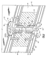
- the example structural cold plate assembly 14 includes a passage 40 through the panel 16.
- the passage 40 is defined through a mount portion 38.
- the mount portion 38 is positioned within the panel 16 and includes machined features for receiving first and second inserts 34, 36.
- the mount portion 38 includes internal threads 60 that mate with threads 68 of the inserts 34, 36.
- the first and second inserts 34, 36 secure the corresponding cold plate 22, 24 to the panel 16 and further define a portion of the fluid passage through the panel 16.
- the inserts 34, 36 secure a portion of the cold plates 22, 24. Additional fastener may also be utilized as required to secure the cold plates 22, 24 to the panel 16.
- the mount portion 38 also receives alignment pins 74 that extend upward into a corresponding opening in each of the cold plates 22, 24.
- the inserts 34, 36 include a threaded portion 68 that threadingly engages corresponding threads defined in the mount portion 38.
- a longitudinal cavity 64 extends through a portion of each insert 34, 36 and is intersected by windows 62. Cooling fluid from the cold plate 22 flows through the windows 62 into the longitudinal passage 64 into the passage 40 and through the second insert 36 into the second cold plate 24.
- the inserts 34, 36 each include a cap 72 that includes a hex opening 70 for receiving a tool to tighten the insert into the mount portion 38.
- a hex opening 70 is disclosed, other shapes that correspond with other tool configuration could also be utilized within the scope of this disclosure.
- Each of the inserts 34, 36 include a seal groove 76 on which the seal 80 can be mounted.
- the seals 78 and 80 are provided on each of the inserts 34, 36 to provide a fluid or airtight seal between the mount portion 38 and the corresponding part of the cold plate.
- the example seals 78, 80 are o-rings that are mounted into corresponding o-ring grooves on the insert and the corresponding circuit plate. As appreciated, other seal configurations could be utilized within the scope of this disclosure.
- the example inserts 34, 36 include the longitudinal passage 64 that terminates at one end at an opening 66 and dead ends at the cap 72 on another end.
- the windows 62 open transverse to the longitudinal passage 64 and communicate cooling medium transverse to the longitudinal passage 64.
- Each of the cold plates 22, 24 includes an opening 56 through which the corresponding insert 34, 36 is installed.
- the opening 56 extends through the top plate 48 and the first circuit plate 52.
- the opening 56 through the top plate 48 and first circuit plate 52 is defined to receive the diameter of the cap 72.
- the circuit plate 54 includes an opening large enough to receive the threaded portion such that a bottom portion of the cap 72 engages a ledge 58 of the circuit plate 54 and compresses the seal 78 sufficiently to provide the desired seal.
- each cold plate 22, 24 includes two fluid circuit plates 52, 54.
- the example cap 72 extends through the fluid circuit plate 52 to align the windows 62 with the second fluid circuit plate 54. Thereby fluid from the second fluid circuit plate 54 is permitted to flow through the windows 62 and into the longitudinally passage 64 that leads further to the second cold plate 24.
- the example inserts 34, 36 can also be configured to provide fluid communication between the first fluid circuit plates 52 of each corresponding cold plate 22, 24. In other words, another set of inserts 34, 36 can be provided within the example structural cold plate assembly 14 that aligns windows 62 with the specific ones of the fluid circuit plates 52, 54 that defines the desired fluid passage between fluid circuit plates in the different cold plates 22, 24.
- the seal 80 provides sealing of between the inserts 34, 36 and the cold plate 22, 24 to further seal against leakage past the threads 68.
- the specific thread configuration between the threads 68 of each insert 34, 36 and the mount portion 38 provides not only a desired sealing feature, but also provides for securing each of the cold plates 22, 24 to the panel 16. Because the threaded inserts 34, 36 are utilized for securing the cold plates 22, 24 to the panel 16, it remains possible to disassemble each of the cold plates 22, 24 from the panel 16 by unthreading the corresponding inserts 34, 36.
- each of the inserts 34, 36 could also be welded to both provide a seal and to prevent disassembly.
- a weld can be provided at an interface between the outer circumference of the cap 72 and the adjacent circuit plate 54, or top plate 48.
- another example insert 84 includes a cap 85 that is welded about its outer perimeter to form the desired seal.
- an electron beam welding process is utilized to form a weld 92 between the outer circumference of the cap 85 and the circuit plate 54.
- the weld 92 provides the desired seal and therefore no seal is provided between the bottom surface of the cap 85 and the circuit plate 52 as is disclosed in the previous example.
- the insert 84 includes seals 88 and 90 that are disposed at the top and bottom of the threads 86.
- the threads 86 engage corresponding threads 82 on the mount portion 38 to both hold the insert 84 and cold plate 22 in place.
- the example insert 84 includes windows 96 that intersect longitudinal passage 94 to define a portion of the passage 40.
- the example structural cooling plate assembly 14 is fabricated by first assembling the panel 16.
- the example panel 16 is assembled by bonding the top and bottom face sheets 42 to the honeycomb portion 46 and frame structure 44 and the mount portion 38.
- the mount portion 38 is positioned where the inserts are desired.
- the example panel 16 -bonds the face sheets 42 to the surfaces utilizing an adhesive. As appreciated other bonding processes such as brazing could also be utilized.
- the face sheets 42 can be fabricated from sheet metal material along with other sheet materials that provide the desired structure and strength properties.
- the first and second cold plates 22, 24 are then assembled to include the desired circuit configurations.
- the example cold plates 22, 24 include two circuit plates each that separate fluid circuits that will be connected by the fluid passage through the panel.
- the cold plates 22, 24 are mounted to the panel 16.
- the openings 56 are then either created, or aligned through each of the cold plates 22, 24 and aligned with each other.
- the cold plates 22, 24 are aligned by engaging the pins 74.
- the inserts 34, 36 are installed.
- the installation of the inserts 34, 36 include mounting of the seals 78, 80 and threading the insert 34, 36 into the corresponding threads of the mount portion 38. With the inserts 34, 36 installed, a passage between both cold plates 22, 24 are formed.
- the inserts 34, 36 can then remain in the threaded condition that provides for disassembly if desired.
- the insert can be welded in place to prevent disassembly and provide a desired seal.
- the example structural cold plate assembly 14 provides a two-sided thermal control structure that is built into the support structure and that reduces the number of exposed fluid conduits and connectors. Moreover, the integral structure of the disclosed structural cold plate assembly 14 aids in assembly and reduces overall package size and weight.
Landscapes
- Engineering & Computer Science (AREA)
- Microelectronics & Electronic Packaging (AREA)
- Physics & Mathematics (AREA)
- Thermal Sciences (AREA)
- Mechanical Engineering (AREA)
- General Engineering & Computer Science (AREA)
- Cooling Or The Like Of Electrical Apparatus (AREA)
- Supports For Pipes And Cables (AREA)
- Fluid-Damping Devices (AREA)
Applications Claiming Priority (1)
| Application Number | Priority Date | Filing Date | Title |
|---|---|---|---|
| US12/748,576 US8931546B2 (en) | 2010-03-29 | 2010-03-29 | Compact two sided cold plate with threaded inserts |
Publications (3)
| Publication Number | Publication Date |
|---|---|
| EP2372290A2 true EP2372290A2 (fr) | 2011-10-05 |
| EP2372290A3 EP2372290A3 (fr) | 2014-02-26 |
| EP2372290B1 EP2372290B1 (fr) | 2018-08-01 |
Family
ID=44343144
Family Applications (1)
| Application Number | Title | Priority Date | Filing Date |
|---|---|---|---|
| EP11250352.9A Active EP2372290B1 (fr) | 2010-03-29 | 2011-03-21 | Ensemble compact formant plaque de refroidissement avec support à inserts filetés |
Country Status (4)
| Country | Link |
|---|---|
| US (1) | US8931546B2 (fr) |
| EP (1) | EP2372290B1 (fr) |
| JP (1) | JP5110492B2 (fr) |
| CN (1) | CN102209458A (fr) |
Cited By (1)
| Publication number | Priority date | Publication date | Assignee | Title |
|---|---|---|---|---|
| EP2672798A3 (fr) * | 2012-06-07 | 2017-01-25 | Hamilton Sundstrand Space Systems International, Inc. | Plaque froide à deux faces compactes avec des tubes de transfert flottants |
Families Citing this family (10)
| Publication number | Priority date | Publication date | Assignee | Title |
|---|---|---|---|---|
| DE102010032078B4 (de) * | 2010-07-23 | 2012-02-16 | Siemens Aktiengesellschaft | Leistungselektronik-Baueinheit für eine Magnetresonanzeinrichtung und Magnetresonanzeinrichtung |
| US8897013B2 (en) | 2011-02-17 | 2014-11-25 | Lear Corporation | Sealed battery charger housing |
| US8804337B2 (en) | 2012-03-26 | 2014-08-12 | Hamilton Sundstrand Space Systems International, Inc. | Structural assembly for cold plate cooling |
| JP2014075488A (ja) * | 2012-10-04 | 2014-04-24 | Toyota Industries Corp | 放熱装置 |
| US8867210B2 (en) * | 2012-10-31 | 2014-10-21 | Deere & Company | Cooling apparatus for an electrical substrate |
| US20140150992A1 (en) * | 2012-11-30 | 2014-06-05 | Raytheon Company | Threaded cooling apparatus with integrated cooling channels and heat exchanger |
| US9497888B2 (en) * | 2013-02-27 | 2016-11-15 | International Business Machines Corporation | Thermal transfer structure(s) and attachment mechanism(s) facilitating cooling of electronics card(s) |
| US20140262158A1 (en) * | 2013-03-15 | 2014-09-18 | Parker-Hannifin Corporation | Two-phase cooling system |
| US9819062B2 (en) | 2014-11-14 | 2017-11-14 | Ford Global Technologies, Llc | Traction battery assembly with thermal device |
| CN111532457B (zh) * | 2020-04-28 | 2021-08-17 | 中国科学院空间应用工程与技术中心 | 一种具有液冷流道的载荷适配器 |
Family Cites Families (39)
| Publication number | Priority date | Publication date | Assignee | Title |
|---|---|---|---|---|
| US255575A (en) * | 1882-03-28 | Beer-cooler | ||
| US1958899A (en) * | 1931-06-30 | 1934-05-15 | Macadams Jesse Edward | Heat transfer apparatus |
| US1926004A (en) * | 1932-01-13 | 1933-09-05 | American Radiator Co | Radiator |
| US2272863A (en) * | 1940-11-04 | 1942-02-10 | Fred M Young | Heat exchange tube protector |
| US2752128A (en) * | 1955-10-17 | 1956-06-26 | Modine Mfg Co | Heat exchange structure |
| FR2433156A1 (fr) * | 1978-08-09 | 1980-03-07 | Commissariat Energie Atomique | Perfectionnement aux echangeurs de chaleur a plaques |
| EP0144579B1 (fr) * | 1983-11-02 | 1987-10-14 | BBC Brown Boveri AG | Corps de refroidissement par liquide de composants semi-conducteurs de puissance |
| US4559580A (en) * | 1983-11-04 | 1985-12-17 | Sundstrand Corporation | Semiconductor package with internal heat exchanger |
| US4562512A (en) * | 1984-07-23 | 1985-12-31 | Sundstrand Corporation | Multiple semiconductor containing package having a heat sink core |
| GB8719473D0 (en) * | 1987-08-18 | 1987-09-23 | Cesaroni A J | Headers for heat exchangers |
| US5088005A (en) * | 1990-05-08 | 1992-02-11 | Sundstrand Corporation | Cold plate for cooling electronics |
| US5129447A (en) * | 1991-05-20 | 1992-07-14 | United Technologies Corporation | Cooled bolting arrangement |
| US5269372A (en) * | 1992-12-21 | 1993-12-14 | International Business Machines Corporation | Intersecting flow network for a cold plate cooling system |
| FR2701600B1 (fr) * | 1993-02-10 | 1995-09-08 | Gec Alsthom Transport Sa | Dispositif de refroidissement de composants electriques de puissance. |
| US6191945B1 (en) * | 1997-07-30 | 2001-02-20 | Hewlett-Packard Company | Cold plate arrangement for cooling processor and companion voltage regulator |
| US5923533A (en) * | 1998-02-17 | 1999-07-13 | Lockheed Martin Corporation | Multiple tile scaleable cooling system for semiconductor components |
| US6349035B1 (en) * | 2000-09-29 | 2002-02-19 | Compaq Information Technologies Group, L.P. | Method and apparatus for tooless mating of liquid cooled cold plate with tapered interposer heat sink |
| US6679315B2 (en) * | 2002-01-14 | 2004-01-20 | Marconi Communications, Inc. | Small scale chip cooler assembly |
| US6967064B2 (en) * | 2002-06-24 | 2005-11-22 | Delphi Technologies, Inc. | Co-flow anode/cathode supply heat exchanger for a solid-oxide fuel cell assembly |
| DE10228263A1 (de) * | 2002-06-25 | 2004-01-22 | Behr Gmbh & Co. | Plattenwärmetauscher in Stapelbauweise |
| US7000684B2 (en) * | 2002-11-01 | 2006-02-21 | Cooligy, Inc. | Method and apparatus for efficient vertical fluid delivery for cooling a heat producing device |
| JP4180359B2 (ja) * | 2002-11-29 | 2008-11-12 | カルソニックカンセイ株式会社 | 熱交換器 |
| US7188488B2 (en) * | 2003-03-12 | 2007-03-13 | Hamilton Sundstrand | Pack and a half condensing cycle pack with combined heat exchangers |
| US7017654B2 (en) * | 2003-03-17 | 2006-03-28 | Cooligy, Inc. | Apparatus and method of forming channels in a heat-exchanging device |
| US7024874B2 (en) * | 2003-09-22 | 2006-04-11 | Hamilton Sundstrand | Aircraft galley chiller system |
| US7188662B2 (en) * | 2004-06-04 | 2007-03-13 | Cooligy, Inc. | Apparatus and method of efficient fluid delivery for cooling a heat producing device |
| US7149087B2 (en) * | 2004-09-08 | 2006-12-12 | Thermal Corp. | Liquid cooled heat sink with cold plate retention mechanism |
| US20060067052A1 (en) * | 2004-09-30 | 2006-03-30 | Llapitan David J | Liquid cooling system |
| US7201217B2 (en) * | 2005-05-24 | 2007-04-10 | Raytheon Company | Cold plate assembly |
| JP2006332393A (ja) * | 2005-05-27 | 2006-12-07 | T Rad Co Ltd | 水冷式ヒートシンク |
| DE102005048492B4 (de) * | 2005-10-07 | 2009-06-04 | Curamik Electronics Gmbh | Elektrisches Modul |
| US7766075B2 (en) * | 2005-12-09 | 2010-08-03 | The Boeing Company | Microchannel heat exchanger |
| US7353864B2 (en) * | 2005-12-23 | 2008-04-08 | Hamilton Sundstrand Corporation | Apparatus for reducing thermal fatigue in heat exchanger cores |
| DE102006037065A1 (de) | 2006-08-08 | 2008-02-21 | Siemens Ag | Kühlplattensystem |
| DE102006050256A1 (de) | 2006-10-23 | 2008-04-30 | Pahls, Hans-Helmut, Dipl.-Ing. | Kühler für elektrische elektronische und andere Bauteile |
| JP2008171840A (ja) * | 2007-01-05 | 2008-07-24 | T Rad Co Ltd | 液冷ヒートシンクおよびその設計方法 |
| JP2008235725A (ja) * | 2007-03-23 | 2008-10-02 | Calsonic Kansei Corp | 水冷式ヒートシンク |
| US7564129B2 (en) * | 2007-03-30 | 2009-07-21 | Nichicon Corporation | Power semiconductor module, and power semiconductor device having the module mounted therein |
| CN101301541A (zh) | 2008-01-29 | 2008-11-12 | 杜建耀 | 一种两面过滤水处理滤材装置 |
-
2010
- 2010-03-29 US US12/748,576 patent/US8931546B2/en active Active
-
2011
- 2011-03-21 EP EP11250352.9A patent/EP2372290B1/fr active Active
- 2011-03-29 CN CN2011100765298A patent/CN102209458A/zh active Pending
- 2011-03-29 JP JP2011071279A patent/JP5110492B2/ja not_active Expired - Fee Related
Non-Patent Citations (1)
| Title |
|---|
| None |
Cited By (1)
| Publication number | Priority date | Publication date | Assignee | Title |
|---|---|---|---|---|
| EP2672798A3 (fr) * | 2012-06-07 | 2017-01-25 | Hamilton Sundstrand Space Systems International, Inc. | Plaque froide à deux faces compactes avec des tubes de transfert flottants |
Also Published As
| Publication number | Publication date |
|---|---|
| US20110232864A1 (en) | 2011-09-29 |
| EP2372290B1 (fr) | 2018-08-01 |
| JP5110492B2 (ja) | 2012-12-26 |
| EP2372290A3 (fr) | 2014-02-26 |
| US8931546B2 (en) | 2015-01-13 |
| CN102209458A (zh) | 2011-10-05 |
| JP2011211203A (ja) | 2011-10-20 |
Similar Documents
| Publication | Publication Date | Title |
|---|---|---|
| EP2372290B1 (fr) | Ensemble compact formant plaque de refroidissement avec support à inserts filetés | |
| US8991478B2 (en) | Compact two sided cold plate with transfer tubes | |
| CN107078243B (zh) | 具有单元固定的电池模块 | |
| EP1596455B1 (fr) | Plaque avec tuyauterie intégrée composée d'une multitude de plaques avec une rainure d'arrêt de transfert de température | |
| EP3582289A1 (fr) | Bloc-batterie et automobile électrique | |
| US10862179B2 (en) | Battery module and high-voltage accumulator | |
| JP6206359B2 (ja) | 半導体装置 | |
| US8522861B2 (en) | Integral cold plate and structural member | |
| WO2019196877A1 (fr) | Bloc-batterie et boîtier de batterie associé | |
| CN112640194B (zh) | 用于牵引电池的电池壳体和用于机动车辆的牵引电池 | |
| US20110226445A1 (en) | Heat exchanger | |
| US20160282059A1 (en) | Layered heat transfer device and method for producing a layered heat transfer device | |
| KR20190020747A (ko) | 열관리 동력 전지 모듈 및 전지팩 | |
| EP1935050B1 (fr) | Dispositif dissipateur de chaleur pour batterie d'alimentation, et batterie d'alimentation utilisant ledit dispositif | |
| CN212676355U (zh) | 散热结构、电池模组以及散热系统 | |
| WO2021249272A1 (fr) | Bloc-batterie et véhicule électrique | |
| US20130233515A1 (en) | Spacecraft radiator panels | |
| CN215680865U (zh) | 电池包箱体、电池包及车辆 | |
| CN211654906U (zh) | 一种电动汽车的液冷电池箱 | |
| CN1972744A (zh) | 微流系统 | |
| EP2672798B1 (fr) | Plaque froide à deux faces compactes avec des tubes de transfert flottants | |
| CN212786395U (zh) | 一种ecu冷却装置 | |
| CN118696450B (zh) | 箱体、箱体组件、电池及用电设备 | |
| CN112186293A (zh) | 散热结构、电池模组、散热系统以及散热系统的控制方法 | |
| CN219832926U (zh) | 电池箱及电池包 |
Legal Events
| Date | Code | Title | Description |
|---|---|---|---|
| PUAI | Public reference made under article 153(3) epc to a published international application that has entered the european phase |
Free format text: ORIGINAL CODE: 0009012 |
|
| AK | Designated contracting states |
Kind code of ref document: A2 Designated state(s): AL AT BE BG CH CY CZ DE DK EE ES FI FR GB GR HR HU IE IS IT LI LT LU LV MC MK MT NL NO PL PT RO RS SE SI SK SM TR |
|
| AX | Request for extension of the european patent |
Extension state: BA ME |
|
| RAP1 | Party data changed (applicant data changed or rights of an application transferred) |
Owner name: HAMILTON SUNDSTRAND SPACE SYSTEMS INTERNATIONAL, I |
|
| PUAL | Search report despatched |
Free format text: ORIGINAL CODE: 0009013 |
|
| AK | Designated contracting states |
Kind code of ref document: A3 Designated state(s): AL AT BE BG CH CY CZ DE DK EE ES FI FR GB GR HR HU IE IS IT LI LT LU LV MC MK MT NL NO PL PT RO RS SE SI SK SM TR |
|
| AX | Request for extension of the european patent |
Extension state: BA ME |
|
| RIC1 | Information provided on ipc code assigned before grant |
Ipc: H01L 23/473 20060101ALI20140121BHEP Ipc: F28F 9/02 20060101ALI20140121BHEP Ipc: H05K 7/20 20060101ALI20140121BHEP Ipc: F28F 3/12 20060101AFI20140121BHEP |
|
| 17P | Request for examination filed |
Effective date: 20140826 |
|
| RBV | Designated contracting states (corrected) |
Designated state(s): AL AT BE BG CH CY CZ DE DK EE ES FI FR GB GR HR HU IE IS IT LI LT LU LV MC MK MT NL NO PL PT RO RS SE SI SK SM TR |
|
| 17Q | First examination report despatched |
Effective date: 20150618 |
|
| STAA | Information on the status of an ep patent application or granted ep patent |
Free format text: STATUS: EXAMINATION IS IN PROGRESS |
|
| GRAP | Despatch of communication of intention to grant a patent |
Free format text: ORIGINAL CODE: EPIDOSNIGR1 |
|
| STAA | Information on the status of an ep patent application or granted ep patent |
Free format text: STATUS: GRANT OF PATENT IS INTENDED |
|
| INTG | Intention to grant announced |
Effective date: 20180216 |
|
| GRAS | Grant fee paid |
Free format text: ORIGINAL CODE: EPIDOSNIGR3 |
|
| GRAA | (expected) grant |
Free format text: ORIGINAL CODE: 0009210 |
|
| STAA | Information on the status of an ep patent application or granted ep patent |
Free format text: STATUS: THE PATENT HAS BEEN GRANTED |
|
| AK | Designated contracting states |
Kind code of ref document: B1 Designated state(s): AL AT BE BG CH CY CZ DE DK EE ES FI FR GB GR HR HU IE IS IT LI LT LU LV MC MK MT NL NO PL PT RO RS SE SI SK SM TR |
|
| REG | Reference to a national code |
Ref country code: GB Ref legal event code: FG4D |
|
| REG | Reference to a national code |
Ref country code: CH Ref legal event code: EP Ref country code: AT Ref legal event code: REF Ref document number: 1024805 Country of ref document: AT Kind code of ref document: T Effective date: 20180815 |
|
| REG | Reference to a national code |
Ref country code: IE Ref legal event code: FG4D |
|
| REG | Reference to a national code |
Ref country code: DE Ref legal event code: R096 Ref document number: 602011050523 Country of ref document: DE |
|
| REG | Reference to a national code |
Ref country code: NL Ref legal event code: MP Effective date: 20180801 |
|
| REG | Reference to a national code |
Ref country code: LT Ref legal event code: MG4D |
|
| REG | Reference to a national code |
Ref country code: AT Ref legal event code: MK05 Ref document number: 1024805 Country of ref document: AT Kind code of ref document: T Effective date: 20180801 |
|
| PG25 | Lapsed in a contracting state [announced via postgrant information from national office to epo] |
Ref country code: BG Free format text: LAPSE BECAUSE OF FAILURE TO SUBMIT A TRANSLATION OF THE DESCRIPTION OR TO PAY THE FEE WITHIN THE PRESCRIBED TIME-LIMIT Effective date: 20181101 Ref country code: AT Free format text: LAPSE BECAUSE OF FAILURE TO SUBMIT A TRANSLATION OF THE DESCRIPTION OR TO PAY THE FEE WITHIN THE PRESCRIBED TIME-LIMIT Effective date: 20180801 Ref country code: NL Free format text: LAPSE BECAUSE OF FAILURE TO SUBMIT A TRANSLATION OF THE DESCRIPTION OR TO PAY THE FEE WITHIN THE PRESCRIBED TIME-LIMIT Effective date: 20180801 Ref country code: SE Free format text: LAPSE BECAUSE OF FAILURE TO SUBMIT A TRANSLATION OF THE DESCRIPTION OR TO PAY THE FEE WITHIN THE PRESCRIBED TIME-LIMIT Effective date: 20180801 Ref country code: IS Free format text: LAPSE BECAUSE OF FAILURE TO SUBMIT A TRANSLATION OF THE DESCRIPTION OR TO PAY THE FEE WITHIN THE PRESCRIBED TIME-LIMIT Effective date: 20181201 Ref country code: RS Free format text: LAPSE BECAUSE OF FAILURE TO SUBMIT A TRANSLATION OF THE DESCRIPTION OR TO PAY THE FEE WITHIN THE PRESCRIBED TIME-LIMIT Effective date: 20180801 Ref country code: GR Free format text: LAPSE BECAUSE OF FAILURE TO SUBMIT A TRANSLATION OF THE DESCRIPTION OR TO PAY THE FEE WITHIN THE PRESCRIBED TIME-LIMIT Effective date: 20181102 Ref country code: NO Free format text: LAPSE BECAUSE OF FAILURE TO SUBMIT A TRANSLATION OF THE DESCRIPTION OR TO PAY THE FEE WITHIN THE PRESCRIBED TIME-LIMIT Effective date: 20181101 Ref country code: FI Free format text: LAPSE BECAUSE OF FAILURE TO SUBMIT A TRANSLATION OF THE DESCRIPTION OR TO PAY THE FEE WITHIN THE PRESCRIBED TIME-LIMIT Effective date: 20180801 Ref country code: LT Free format text: LAPSE BECAUSE OF FAILURE TO SUBMIT A TRANSLATION OF THE DESCRIPTION OR TO PAY THE FEE WITHIN THE PRESCRIBED TIME-LIMIT Effective date: 20180801 Ref country code: PL Free format text: LAPSE BECAUSE OF FAILURE TO SUBMIT A TRANSLATION OF THE DESCRIPTION OR TO PAY THE FEE WITHIN THE PRESCRIBED TIME-LIMIT Effective date: 20180801 |
|
| PG25 | Lapsed in a contracting state [announced via postgrant information from national office to epo] |
Ref country code: LV Free format text: LAPSE BECAUSE OF FAILURE TO SUBMIT A TRANSLATION OF THE DESCRIPTION OR TO PAY THE FEE WITHIN THE PRESCRIBED TIME-LIMIT Effective date: 20180801 Ref country code: HR Free format text: LAPSE BECAUSE OF FAILURE TO SUBMIT A TRANSLATION OF THE DESCRIPTION OR TO PAY THE FEE WITHIN THE PRESCRIBED TIME-LIMIT Effective date: 20180801 Ref country code: AL Free format text: LAPSE BECAUSE OF FAILURE TO SUBMIT A TRANSLATION OF THE DESCRIPTION OR TO PAY THE FEE WITHIN THE PRESCRIBED TIME-LIMIT Effective date: 20180801 Ref country code: ES Free format text: LAPSE BECAUSE OF FAILURE TO SUBMIT A TRANSLATION OF THE DESCRIPTION OR TO PAY THE FEE WITHIN THE PRESCRIBED TIME-LIMIT Effective date: 20180801 |
|
| PG25 | Lapsed in a contracting state [announced via postgrant information from national office to epo] |
Ref country code: RO Free format text: LAPSE BECAUSE OF FAILURE TO SUBMIT A TRANSLATION OF THE DESCRIPTION OR TO PAY THE FEE WITHIN THE PRESCRIBED TIME-LIMIT Effective date: 20180801 Ref country code: CZ Free format text: LAPSE BECAUSE OF FAILURE TO SUBMIT A TRANSLATION OF THE DESCRIPTION OR TO PAY THE FEE WITHIN THE PRESCRIBED TIME-LIMIT Effective date: 20180801 Ref country code: EE Free format text: LAPSE BECAUSE OF FAILURE TO SUBMIT A TRANSLATION OF THE DESCRIPTION OR TO PAY THE FEE WITHIN THE PRESCRIBED TIME-LIMIT Effective date: 20180801 |
|
| REG | Reference to a national code |
Ref country code: DE Ref legal event code: R097 Ref document number: 602011050523 Country of ref document: DE |
|
| PG25 | Lapsed in a contracting state [announced via postgrant information from national office to epo] |
Ref country code: SK Free format text: LAPSE BECAUSE OF FAILURE TO SUBMIT A TRANSLATION OF THE DESCRIPTION OR TO PAY THE FEE WITHIN THE PRESCRIBED TIME-LIMIT Effective date: 20180801 Ref country code: SM Free format text: LAPSE BECAUSE OF FAILURE TO SUBMIT A TRANSLATION OF THE DESCRIPTION OR TO PAY THE FEE WITHIN THE PRESCRIBED TIME-LIMIT Effective date: 20180801 Ref country code: DK Free format text: LAPSE BECAUSE OF FAILURE TO SUBMIT A TRANSLATION OF THE DESCRIPTION OR TO PAY THE FEE WITHIN THE PRESCRIBED TIME-LIMIT Effective date: 20180801 |
|
| PLBE | No opposition filed within time limit |
Free format text: ORIGINAL CODE: 0009261 |
|
| STAA | Information on the status of an ep patent application or granted ep patent |
Free format text: STATUS: NO OPPOSITION FILED WITHIN TIME LIMIT |
|
| 26N | No opposition filed |
Effective date: 20190503 |
|
| PG25 | Lapsed in a contracting state [announced via postgrant information from national office to epo] |
Ref country code: SI Free format text: LAPSE BECAUSE OF FAILURE TO SUBMIT A TRANSLATION OF THE DESCRIPTION OR TO PAY THE FEE WITHIN THE PRESCRIBED TIME-LIMIT Effective date: 20180801 |
|
| PG25 | Lapsed in a contracting state [announced via postgrant information from national office to epo] |
Ref country code: MC Free format text: LAPSE BECAUSE OF FAILURE TO SUBMIT A TRANSLATION OF THE DESCRIPTION OR TO PAY THE FEE WITHIN THE PRESCRIBED TIME-LIMIT Effective date: 20180801 |
|
| REG | Reference to a national code |
Ref country code: CH Ref legal event code: PL |
|
| PG25 | Lapsed in a contracting state [announced via postgrant information from national office to epo] |
Ref country code: LU Free format text: LAPSE BECAUSE OF NON-PAYMENT OF DUE FEES Effective date: 20190321 |
|
| REG | Reference to a national code |
Ref country code: BE Ref legal event code: MM Effective date: 20190331 |
|
| PG25 | Lapsed in a contracting state [announced via postgrant information from national office to epo] |
Ref country code: IE Free format text: LAPSE BECAUSE OF NON-PAYMENT OF DUE FEES Effective date: 20190321 Ref country code: LI Free format text: LAPSE BECAUSE OF NON-PAYMENT OF DUE FEES Effective date: 20190331 Ref country code: CH Free format text: LAPSE BECAUSE OF NON-PAYMENT OF DUE FEES Effective date: 20190331 |
|
| PG25 | Lapsed in a contracting state [announced via postgrant information from national office to epo] |
Ref country code: BE Free format text: LAPSE BECAUSE OF NON-PAYMENT OF DUE FEES Effective date: 20190331 |
|
| PG25 | Lapsed in a contracting state [announced via postgrant information from national office to epo] |
Ref country code: TR Free format text: LAPSE BECAUSE OF FAILURE TO SUBMIT A TRANSLATION OF THE DESCRIPTION OR TO PAY THE FEE WITHIN THE PRESCRIBED TIME-LIMIT Effective date: 20180801 |
|
| PGFP | Annual fee paid to national office [announced via postgrant information from national office to epo] |
Ref country code: IT Payment date: 20200218 Year of fee payment: 10 |
|
| PG25 | Lapsed in a contracting state [announced via postgrant information from national office to epo] |
Ref country code: MT Free format text: LAPSE BECAUSE OF NON-PAYMENT OF DUE FEES Effective date: 20190321 Ref country code: PT Free format text: LAPSE BECAUSE OF FAILURE TO SUBMIT A TRANSLATION OF THE DESCRIPTION OR TO PAY THE FEE WITHIN THE PRESCRIBED TIME-LIMIT Effective date: 20181201 |
|
| PG25 | Lapsed in a contracting state [announced via postgrant information from national office to epo] |
Ref country code: CY Free format text: LAPSE BECAUSE OF FAILURE TO SUBMIT A TRANSLATION OF THE DESCRIPTION OR TO PAY THE FEE WITHIN THE PRESCRIBED TIME-LIMIT Effective date: 20180801 |
|
| PG25 | Lapsed in a contracting state [announced via postgrant information from national office to epo] |
Ref country code: HU Free format text: LAPSE BECAUSE OF FAILURE TO SUBMIT A TRANSLATION OF THE DESCRIPTION OR TO PAY THE FEE WITHIN THE PRESCRIBED TIME-LIMIT; INVALID AB INITIO Effective date: 20110321 |
|
| PG25 | Lapsed in a contracting state [announced via postgrant information from national office to epo] |
Ref country code: IT Free format text: LAPSE BECAUSE OF NON-PAYMENT OF DUE FEES Effective date: 20210321 |
|
| PG25 | Lapsed in a contracting state [announced via postgrant information from national office to epo] |
Ref country code: MK Free format text: LAPSE BECAUSE OF FAILURE TO SUBMIT A TRANSLATION OF THE DESCRIPTION OR TO PAY THE FEE WITHIN THE PRESCRIBED TIME-LIMIT Effective date: 20180801 |
|
| P01 | Opt-out of the competence of the unified patent court (upc) registered |
Free format text: CASE NUMBER: UPC_APP_0016531_2372290/2025 Effective date: 20251209 |
|
| PGFP | Annual fee paid to national office [announced via postgrant information from national office to epo] |
Ref country code: GB Payment date: 20260219 Year of fee payment: 16 |
|
| PGFP | Annual fee paid to national office [announced via postgrant information from national office to epo] |
Ref country code: DE Payment date: 20260219 Year of fee payment: 16 |
|
| PGFP | Annual fee paid to national office [announced via postgrant information from national office to epo] |
Ref country code: FR Payment date: 20260219 Year of fee payment: 16 |