EP2372294B1 - Abschussmechanismus für ein sportgewehr - Google Patents
Abschussmechanismus für ein sportgewehr Download PDFInfo
- Publication number
- EP2372294B1 EP2372294B1 EP08875591A EP08875591A EP2372294B1 EP 2372294 B1 EP2372294 B1 EP 2372294B1 EP 08875591 A EP08875591 A EP 08875591A EP 08875591 A EP08875591 A EP 08875591A EP 2372294 B1 EP2372294 B1 EP 2372294B1
- Authority
- EP
- European Patent Office
- Prior art keywords
- trigger
- accordance
- safety catch
- aperture
- stud
- Prior art date
- Legal status (The legal status is an assumption and is not a legal conclusion. Google has not performed a legal analysis and makes no representation as to the accuracy of the status listed.)
- Active
Links
Images

Classifications
-
- F—MECHANICAL ENGINEERING; LIGHTING; HEATING; WEAPONS; BLASTING
- F41—WEAPONS
- F41A—FUNCTIONAL FEATURES OR DETAILS COMMON TO BOTH SMALLARMS AND ORDNANCE, e.g. CANNONS; MOUNTINGS FOR SMALLARMS OR ORDNANCE
- F41A17/00—Safety arrangements, e.g. safeties
- F41A17/46—Trigger safeties, i.e. means for preventing trigger movement
- F41A17/48—Automatically operated trigger safeties, i.e. operated by breech opening or closing movement
- F41A17/50—Automatically operated trigger safeties, i.e. operated by breech opening or closing movement by breakdown action
Definitions
- a trigger mechanism for a sporting rifle of the type that comprises a piston, a rigid profile and a trigger safety catch and because it also has a wall, firmly attached to the rigid profile, which comprises the trigger and safety catch on one of the faces of said wall and similarly with the other face free, a first stud firmly attached to the trigger, a cover that partially covers the trigger and safety catch and said cover consists of an aperture, in the form of a slider, allowing the first stud to pass through it and for the movement of said first stud along the length of said aperture and a slider arranged over the cover in which, with the barrel broken, the referred slider will block the movement of said stud along the length of the aperture, thus immobilising the trigger and, in the closed barrel position, the mentioned slider allows the movement of the first stud along the aperture.
- the inventor is known in the sporting rifle sector as a great innovator, especially in relation to compressed air and CO 2 rifles and pistols. Within this line improvement, this patent refers to a trigger for sporting rifles.
- Spanish Patent 0493802 ( ES8104552 ) "Compressed air gun", is known from 1980, in the name of AIR MATCH, S.A.R.L., which refers to a compressed air gun. It basically comprises a frame, a barrel mounted on the same, a butt that can be closed against a stationary shoulder, a chamber with a displaceable piston to action of suction and compression air a trigger mechanism, which can be applied to or separated from the block in its assembly.
- the compression chamber closes and opens by the valve and communicates with the barrel by the passes.
- the piston is bolted to an operating lever to action the suction and compression movements. Firing is produced by trigger action which, by means of a series of levers and mechanisms, operates the impulse lever and the valve. Of application for mounting in pistol or carbine shaped.
- European Patent 0467089 "Semi-automatic compressed gas pistol” is also known from 1991, in the name of Mr Thomas G. KOTSIOPOULOS, which refers to a compressed gas pistol fitted with a semi-automatic firing mechanism to allow sequences of successive shots.
- the trigger mechanism includes a lock with a latch arm, with a cam at one end and interconnection elements at the other end. The cam is positioned to close the firing chamber as the latch arm rotates. The interconnection is positioned to releases an actuator bolt as the latch arm rotates. A rewind spring repositions the actuator bolt in order to link up with the interconnection element once the firing chamber is discharged.
- German Patent DE1810211 "Kipplaufdruck Kunststoffwaffe mit byer Lauf-Abzugêt” in the name of Mayer & Grammerlspacher Dianawerk, which refers to a break barrel for airguns, with combined trigger safety which comprises a weak recoil spring for the purpose of easy opening and closing of the weapon and also a strong spring (retainer spring) for the purpose of secure persistence of the barrel during firing use.
- the tension of said strong spring is realized by a lifting roller.
- This invention is an improvement sporting rifle sector in concrete in the compressed air or CO 2
- the inventor goes one step further in the idea of providing a maximum quality product, without any operating errors or failures, together with simple mechanical assembly.
- a trigger mechanism has been developed based on assembling the entire mechanism on a fixed profile of the sporting rifle, as if they were different layers, which facilitates both assembly and disassembly.
- Such mechanisms usually require assembly on both sides of the rifle, fitting covers on one side with another to cover the mechanism.
- a rigid profile has been developed that is used for, on the one hand, a chamber support and, on the other, extends downwards in the form of a wall and forms a support for the entire trigger mechanism and the piston release mechanism.
- Assembly is performed in the form of layers and in this way facilitates the assembly, with significant reductions in costs and handling time.
- the piston blocking time has been improved when loading the rifle because the rod, on the one hand, is coupled to a lever mechanism and, on the other, to a slider which, moved when the rifle is articulated for loading, it slides and blocks the trigger. Because this function is performed with two articulated parts, loading safety catch operation is guaranteed since any possible misalignment or alignment defects will not block the system, thus improving efficiency.
- Safety catch efficiency has also been improved, which reduces costs. This was achieved by using an ellipsoidal aperture, with a narrowing in the central zone. This special configuration creates two safety catch positions and, in the activated position, this blocks the trigger preventing it from being operated.
- Another improvement of this invention is that the trigger is a single piece and is automatically centred by a stud.
- a trigger mechanism for a sporting rifle of the type comprising a piston, rigid profile, a trigger and trigger safety catch characterised in that it has a wall, firmly attached to the rigid profile, which comprises the trigger and safety catch on one of the faces of said wall and similarly with the other face free, a first stud firmly attached to the trigger, a cover that partially covers the trigger and safety catch and said cover consists of an opening, in the form of a slider, allowing the first stud to pass through it and for the movement of said first stud along the length of said aperture and a slider arranged over the cover, in which, with the barrel broken, the referred slider will block the movement of said first stud along the length of the aperture, thus immobilising the trigger and, in the closed barrel position, the mentioned slider allows the movement of the first stud along the aperture.
- Figure 1 illustrates barrel 1 that is joined to chamber 4 by a second articulation 8, a lever mechanism 2, with its first articulation 7, a rod 3, a trigger 5, a safety catch 6 and a slider 9.
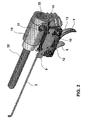
- Figure 2 represents rod 3, slider 9, trigger 5, with first spring 13, safety catch 6, rigid profile 14, spring guide 32, damping washer 31, cover 12 and trigger stud 10.
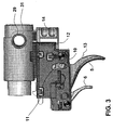
- Figure 3 shows rigid profile 14, pass-through orifice 29, damping washer 31, cover 12, with aperture 11 for trigger stud 10, mentioned trigger 5, with first spring 13 and safety catch 6.
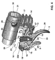
- Figure 4 contains rigid profile 14, with its wall 27, pass-through orifices 29, 30, damping washer 31, safety catch 6, trigger 5, with its stud 10, its shaft 35 and its projection 24, a first slot 25, second slot 26, first spring 13, aperture 16 in the safety catch crossed by a stud 15 on the rigid profile, counterpawl 19, anti-fall safety catch 22 in initial position, anti-fall safety catch 22a in a second position, second spring 17 and pawl 18, with its tooth 23, its elongated mounting hole 53 and stop 20.
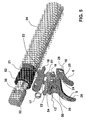
- Figure 5 shows trigger 5, trigger shaft 35, its projection 24, first slot 25, second slot 26, first spring 13, second spring 17, safety catch 6, with its aperture 16, throttle point 28, counter pawl 19, with its necking 54, and interference zone 51, anti-fall safety catch 22, pawl 18, with its tooth 23, contact zone 50, spring 34, spring guide 32 with pass-through orifice 30, spacer 52 and piston 21.
- the sportsman first loads the rifle by breaking barrel 1. This means by gripping barrel 1 and chamber 4 they will articulate by the first and second articulations 7, 8, which allows the pellet or similar to be inserted inside barrel 1.
- lever mechanism 2 moves in the opposite direction to barrel 1 and moves rod 3 which, in turn, is coupled to slider 9, thus pushing slider 9.
- slider 9 is arranged on cover 12 ( Fig. 2 ).
- cover 12 Fig. 2
- referred slider 9 blocks the movement of first stud 10 along aperture 11. This immobilises trigger 5 and hence, the rifle cannot fire.
- the trigger comprises projection 24 that is introduced into first slot 25, belonging to mentioned safety catch 6. In this way, if safety catch 6 is not released, when attempts are made to move trigger 5, projection 24 remains blocked by safety catch 6 and hence, trigger 5 is blocked and the sporting rifle cannot be fired.
- Safety catch 6 comprises kidney-shaped aperture 16, with choke point 28, which defines the two halves, upper and lower ones. Said aperture is crossed by fixed stud 15, belonging to rigid profile 14. In the safety position in this exemplary embodiment, stud 15 is in the lower half of aperture 16, blocking all possible action of trigger 5 and is assisted by throttle point 28 that stabilises the safety catch position.
- safety catch 6 When safety catch 6 is moved by a finger, it overcomes the resistance of throttle point 28 and safety catch 6 moves leaving stud 15 in the upper half of aperture 16, with trigger 5 in the unblocked position.
- said trigger shaft 35 crosses trigger 5 and anti-fall safety catch 22.
- Anti-fall safety catch 22 is intended to prevent the pawl 18 from coming down until the trigger is no longer pressed. In this way, when anti-fall safety catch 22 stops being in contact with stop 20 of pawl 18, pawl 18 is then able to move downwards.
- contact zone 50 of trigger 5 with counterpawl 19 causes trigger 5 to rotate due to finger pressure of the sportsman, this contact zone 50 rotates counter pawl 19 which reduces the space of interference zone 51 and releases pawl 18 which then falls due to the action of the vertical force component that piston 21 exerts on tooth 23, pushed by spring 34. Tooth 23 releases rifle piston 21, which then fires.
- first spring 13 and second spring 17 return the various elements to their initial positions except safety catch 6, which is left in manual operation by the sportsman.
- Elongated mounting hole 53 ( Fig. 4 ) is used to load the rifle.
- piston 21 moves backwards, it pushes pawl 18, which also moves because it is allowed to do so by elongated mounting hole 53, in this way it eliminates interference zone 51 and also the interference of anti-fall safety catch 22 with stud 20, so that pawl 18 falls into upper necking 54 of pawl 19, allowing it to pass above piston 21.
- tooth 23 reaches the piston 21, tooth 23 is able to move up under the force of spring 17.
- spacer 52 The purpose of the spacer 52 is to protect tooth 23 so that spring 34 does not eject it and thus free piston 21. It also used to damp rigid profile 14 to prevent spring 34 damaging it.
- Said damping washers 31 prevent vibrations and the tendency of chamber 4 to drag forward from damaging the trigger mechanism.
Landscapes
- Engineering & Computer Science (AREA)
- General Engineering & Computer Science (AREA)
- Toys (AREA)
- Portable Nailing Machines And Staplers (AREA)
- Mechanical Pencils And Projecting And Retracting Systems Therefor, And Multi-System Writing Instruments (AREA)
- Aiming, Guidance, Guns With A Light Source, Armor, Camouflage, And Targets (AREA)
Claims (14)
- Abzugsmechanismus für Sportgewehre mit einem Kolben (21), einem festen Profil (14), in dem eine Federführung (32) untergebracht ist und das als Kammeraufnahme dient, einem Abzug (5) sowie einem Abzugssicherungshebel (6), wobei der Abzugsmechanismus folgendes aufweist:• eine Wand (27), die fest an diesem festen Profil (14) angebracht ist, wobei der Abzug (5) und der Abzugssicherungshebel (6) über einer der Flächen dieser Wand (27) angeordnet ist und die andere Fläche dieser Wand (27) frei ist,• einen am Abzug (5) fest angebrachten Bolzen (10),• eine Abdeckung (12), die den Abzug (5) und den Sicherungshebel (6) teilweise abdeckt, wobei die Abdeckung (12) eine Öffnung (11) aufweist, durch die der erste Bolzen (10) geführt und an dieser entlang verschoben werden kann, sowie• einen Schieber (9), der über der Abdeckung (12) angeordnet ist, wobei der Schieber (9) die Bewegung des ersten Bolzens (10) entlang der Öffnung (11) bei geöffneter Laufstellung sperrt und den Abzug (5) dadurch arretiert und der Schieber (9) die Bewegung des ersten Bolzens (10) entlang der Öffnung (11) bei geschlossener Laufstellung freigibt.
- Mechanismus nach Anspruch 1, dadurch gekennzeichnet, daß der Schieber (9) an eine Stange (3) gekoppelt ist, die mit dem Hebelmechanismus (2) des Laufs (1) gekoppelt ist.
- Mechanismus nach Anspruch 1, dadurch gekennzeichnet, daß er zwischen der Wand (27) und der Abdeckung (12) eine Klinke (18) mit Zahn (23) aufweist, durch die ein Kolben (21) gesperrt wird.
- Mechanismus nach Anspruch 1, dadurch gekennzeichnet, daß er im Sicherungshebel (6) eine erste Nut (25) aufweist, in der ein Abzugsvorsprung (24) untergebracht ist.
- Mechanismus nach Anspruch 3 und 4, dadurch gekennzeichnet, daß er eine Gegenklinke (19) aufweist, die gleichzeitig an einer Klinke (18) und dem Abzug (5) anliegt, und diese Gegenklinke (19) analog mit dem Abzug (5) kinetisch gekoppelt ist, wobei der genannte erste Abschnitt (19) die Bewegung der Klinke (18) sperrt und bei Bewegung des Abzugs die Sperrung (5) freigibt.
- Mechanismus nach Anspruch 5, dadurch gekennzeichnet, daß er in der Gegenklinke (19) eine obere Verengung (54) aufweist.
- Mechanismus nach Anspruch 5, dadurch gekennzeichnet, daß er einen mit dem Abzug (5) in Verbindung stehenden störungssicheren Sicherungshebel (22) aufweist, wobei der Sicherungshebel (22) an einem Anschlag (20) an der Klinke (18) anliegt, wodurch der Sicherungshebel (22) arretiert wird.
- Mechanismus nach Anspruch 7, dadurch gekennzeichnet, daß er eine Abzugsachse (35) aufweist, die durch den Abzug (5) und den störungssicheren Sicherungshebel (22) führt.
- Mechanismus nach Anspruch 7, dadurch gekennzeichnet, daß der Abzug (5) eine zweite Nut (26) aufweist, in der eine erste Feder (13) vorhanden ist.
- Mechanismus nach Anspruch 5, dadurch gekennzeichnet, daß er eine zweite Feder (17) aufweist, die durch die Klinke (18) und Gegenklinke (19) zusammengedrückt werden.
- Mechanismus nach Anspruch 1, dadurch gekennzeichnet, daß er im Sicherungshebel (6) eine Öffnung (16) für den zweiten Bolzen (15) aufweist und die Öffnung (16) einen Drosselpunkt (28) aufweist, durch den zwei Räume definiert sind, wobei der erste den Abzug sperrt und der zweite ihn freigibt.
- Mechanismus nach Anspruch 11, dadurch gekennzeichnet, daß die Öffnung (16) in Form einer Niere vorliegt.
- Mechanismus nach Anspruch 1, dadurch gekennzeichnet, daß das genannte feste Profil (14) Durchgangsöffnungen (29, 30) aufweist und daß über den Durchgangsöffnungen (29, 30) Dämpferscheiben (31) angeordnet sind.
- Mechanismus nach Anspruch 5, dadurch gekennzeichnet, daß er am Ende des Kolbens (21) ein Abstandstück (52) sowie eine Feder (34) aufweist, die den Kolben (21) umgibt.
Applications Claiming Priority (1)
| Application Number | Priority Date | Filing Date | Title |
|---|---|---|---|
| PCT/ES2008/070216 WO2010061010A1 (es) | 2008-11-27 | 2008-11-27 | Mecanismo de disparo para carabina deportiva |
Publications (2)
| Publication Number | Publication Date |
|---|---|
| EP2372294A1 EP2372294A1 (de) | 2011-10-05 |
| EP2372294B1 true EP2372294B1 (de) | 2013-03-20 |
Family
ID=40975372
Family Applications (1)
| Application Number | Title | Priority Date | Filing Date |
|---|---|---|---|
| EP08875591A Active EP2372294B1 (de) | 2008-11-27 | 2008-11-27 | Abschussmechanismus für ein sportgewehr |
Country Status (7)
| Country | Link |
|---|---|
| US (1) | US8490310B2 (de) |
| EP (1) | EP2372294B1 (de) |
| CN (1) | CN102227606B (de) |
| ES (1) | ES2404329T3 (de) |
| MX (1) | MX2011005601A (de) |
| RU (1) | RU2478894C2 (de) |
| WO (1) | WO2010061010A1 (de) |
Families Citing this family (4)
| Publication number | Priority date | Publication date | Assignee | Title |
|---|---|---|---|---|
| ES2413495B1 (es) * | 2012-01-13 | 2014-10-23 | Gamo Outdoor, S.L. | Mecanismo de disparo para carabina deportiva |
| CN104422337A (zh) * | 2013-08-21 | 2015-03-18 | 李希龙 | 一种可多次压气储能的气枪动力装置 |
| US9194639B1 (en) | 2014-11-14 | 2015-11-24 | Crosman Corporation | Dual sear trigger assembly with centered interlock |
| US11274894B1 (en) | 2021-06-04 | 2022-03-15 | Freefall Inc. | Enhanced fire-control system |
Family Cites Families (14)
| Publication number | Priority date | Publication date | Assignee | Title |
|---|---|---|---|---|
| US495639A (en) * | 1893-04-18 | Breakdown breech-loading gun | ||
| US523130A (en) * | 1894-07-17 | Ejector for breakdown guns | ||
| US594863A (en) * | 1897-12-07 | Otto p | ||
| US495298A (en) * | 1893-04-11 | Ward george parry | ||
| US236791A (en) * | 1881-01-18 | Breech-loading fire-arm | ||
| US1792732A (en) * | 1929-04-08 | 1931-02-17 | Bishop M Crawford | Gunlock |
| BE377703A (de) * | 1931-02-27 | |||
| DE1113164B (de) * | 1958-05-21 | 1961-08-24 | Nis Petersen | Entspannungsvorrichtung fuer Jagdgewehre |
| US3153874A (en) * | 1962-08-01 | 1964-10-27 | Merrill Rex Raymond | Hinged barrel firearm with trigger safety means |
| FR1378793A (fr) * | 1964-01-10 | 1964-11-13 | Friedr Wilh Heym Fa | Arme de sûreté |
| DE1810211A1 (de) * | 1968-11-21 | 1970-06-04 | Mayer Grammelspach Dianawerk | Kipplaufdruckluftwaffe mit kombinierter Lauf-Abzugsicherung |
| IT1120690B (it) | 1979-08-13 | 1986-03-26 | Air Match Sarl | Arma da tiro ad aria precompressa |
| EP0467089B1 (de) | 1990-06-21 | 1995-10-04 | Thomas G. Kotsiopoulos | Halbautomatische Druckgaswaffe |
| CN2884122Y (zh) * | 2006-04-21 | 2007-03-28 | 雄鹰投资集团有限公司 | 立式双管猎枪的击发装置 |
-
2008
- 2008-11-27 WO PCT/ES2008/070216 patent/WO2010061010A1/es not_active Ceased
- 2008-11-27 ES ES08875591T patent/ES2404329T3/es active Active
- 2008-11-27 EP EP08875591A patent/EP2372294B1/de active Active
- 2008-11-27 MX MX2011005601A patent/MX2011005601A/es unknown
- 2008-11-27 CN CN200880132095.5A patent/CN102227606B/zh active Active
- 2008-11-27 US US13/130,679 patent/US8490310B2/en active Active
- 2008-11-27 RU RU2011126137/11A patent/RU2478894C2/ru active
Also Published As
| Publication number | Publication date |
|---|---|
| RU2011126137A (ru) | 2013-01-10 |
| CN102227606A (zh) | 2011-10-26 |
| ES2404329T3 (es) | 2013-05-27 |
| RU2478894C2 (ru) | 2013-04-10 |
| HK1160210A1 (en) | 2012-08-10 |
| MX2011005601A (es) | 2011-06-16 |
| EP2372294A1 (de) | 2011-10-05 |
| US8490310B2 (en) | 2013-07-23 |
| WO2010061010A1 (es) | 2010-06-03 |
| US20110225863A1 (en) | 2011-09-22 |
| CN102227606B (zh) | 2014-04-09 |
Similar Documents
| Publication | Publication Date | Title |
|---|---|---|
| AU2023200365B2 (en) | Selective fire firearm systems and methods | |
| EP3129739B1 (de) | Abzugssystem für feuerwaffen | |
| US6374526B1 (en) | Firing pin block for pistol | |
| US5680722A (en) | Fire control system for firearms | |
| US11578939B2 (en) | Safety mechanism for firearms | |
| US8459172B2 (en) | M249 rifle with select fire mechanism for selective fully-automatic and semi-automatic operation | |
| US8490310B2 (en) | Trigger mechanism for sporting rifle | |
| US7987763B1 (en) | Double action firing pin system | |
| AU2008309924A1 (en) | Safety mechanism for a latch | |
| US5992075A (en) | Repeating gun having an axially guided repeating unit | |
| KR20200128525A (ko) | 화기를 위한 방아쇠 장치 | |
| US11774198B2 (en) | Rifle with recoil group | |
| US8453554B2 (en) | M60 rifle with select fire mechanism for selective fully-automatic semi-automatic operation | |
| KR20200128524A (ko) | 화기를 위한 안전장치 | |
| HK1160210B (en) | Firing mechanism for a sporting rifle | |
| EP2053336B1 (de) | Einzelladergewehr | |
| US7665455B2 (en) | Compressed gas operated pistol | |
| EP0865603A1 (de) | Unterwasserpistole für sportzwecke | |
| DE256061C (de) |
Legal Events
| Date | Code | Title | Description |
|---|---|---|---|
| PUAI | Public reference made under article 153(3) epc to a published international application that has entered the european phase |
Free format text: ORIGINAL CODE: 0009012 |
|
| 17P | Request for examination filed |
Effective date: 20110627 |
|
| AK | Designated contracting states |
Kind code of ref document: A1 Designated state(s): AT BE BG CH CY CZ DE DK EE ES FI FR GB GR HR HU IE IS IT LI LT LU LV MC MT NL NO PL PT RO SE SI SK TR |
|
| DAX | Request for extension of the european patent (deleted) | ||
| 17Q | First examination report despatched |
Effective date: 20120417 |
|
| REG | Reference to a national code |
Ref country code: HK Ref legal event code: DE Ref document number: 1160210 Country of ref document: HK |
|
| GRAP | Despatch of communication of intention to grant a patent |
Free format text: ORIGINAL CODE: EPIDOSNIGR1 |
|
| GRAS | Grant fee paid |
Free format text: ORIGINAL CODE: EPIDOSNIGR3 |
|
| GRAA | (expected) grant |
Free format text: ORIGINAL CODE: 0009210 |
|
| AK | Designated contracting states |
Kind code of ref document: B1 Designated state(s): AT BE BG CH CY CZ DE DK EE ES FI FR GB GR HR HU IE IS IT LI LT LU LV MC MT NL NO PL PT RO SE SI SK TR |
|
| REG | Reference to a national code |
Ref country code: GB Ref legal event code: FG4D |
|
| REG | Reference to a national code |
Ref country code: CH Ref legal event code: EP |
|
| REG | Reference to a national code |
Ref country code: IE Ref legal event code: FG4D |
|
| REG | Reference to a national code |
Ref country code: AT Ref legal event code: REF Ref document number: 602330 Country of ref document: AT Kind code of ref document: T Effective date: 20130415 |
|
| REG | Reference to a national code |
Ref country code: DE Ref legal event code: R096 Ref document number: 602008023152 Country of ref document: DE Effective date: 20130508 |
|
| REG | Reference to a national code |
Ref country code: SE Ref legal event code: TRGR |
|
| REG | Reference to a national code |
Ref country code: ES Ref legal event code: FG2A Ref document number: 2404329 Country of ref document: ES Kind code of ref document: T3 Effective date: 20130527 |
|
| REG | Reference to a national code |
Ref country code: NL Ref legal event code: T3 |
|
| PG25 | Lapsed in a contracting state [announced via postgrant information from national office to epo] |
Ref country code: LT Free format text: LAPSE BECAUSE OF FAILURE TO SUBMIT A TRANSLATION OF THE DESCRIPTION OR TO PAY THE FEE WITHIN THE PRESCRIBED TIME-LIMIT Effective date: 20130320 Ref country code: NO Free format text: LAPSE BECAUSE OF FAILURE TO SUBMIT A TRANSLATION OF THE DESCRIPTION OR TO PAY THE FEE WITHIN THE PRESCRIBED TIME-LIMIT Effective date: 20130620 Ref country code: BG Free format text: LAPSE BECAUSE OF FAILURE TO SUBMIT A TRANSLATION OF THE DESCRIPTION OR TO PAY THE FEE WITHIN THE PRESCRIBED TIME-LIMIT Effective date: 20130620 |
|
| REG | Reference to a national code |
Ref country code: AT Ref legal event code: MK05 Ref document number: 602330 Country of ref document: AT Kind code of ref document: T Effective date: 20130320 |
|
| REG | Reference to a national code |
Ref country code: LT Ref legal event code: MG4D |
|
| PG25 | Lapsed in a contracting state [announced via postgrant information from national office to epo] |
Ref country code: SI Free format text: LAPSE BECAUSE OF FAILURE TO SUBMIT A TRANSLATION OF THE DESCRIPTION OR TO PAY THE FEE WITHIN THE PRESCRIBED TIME-LIMIT Effective date: 20130320 Ref country code: GR Free format text: LAPSE BECAUSE OF FAILURE TO SUBMIT A TRANSLATION OF THE DESCRIPTION OR TO PAY THE FEE WITHIN THE PRESCRIBED TIME-LIMIT Effective date: 20130621 Ref country code: LV Free format text: LAPSE BECAUSE OF FAILURE TO SUBMIT A TRANSLATION OF THE DESCRIPTION OR TO PAY THE FEE WITHIN THE PRESCRIBED TIME-LIMIT Effective date: 20130320 Ref country code: FI Free format text: LAPSE BECAUSE OF FAILURE TO SUBMIT A TRANSLATION OF THE DESCRIPTION OR TO PAY THE FEE WITHIN THE PRESCRIBED TIME-LIMIT Effective date: 20130320 |
|
| PG25 | Lapsed in a contracting state [announced via postgrant information from national office to epo] |
Ref country code: HR Free format text: LAPSE BECAUSE OF FAILURE TO SUBMIT A TRANSLATION OF THE DESCRIPTION OR TO PAY THE FEE WITHIN THE PRESCRIBED TIME-LIMIT Effective date: 20130320 Ref country code: BE Free format text: LAPSE BECAUSE OF FAILURE TO SUBMIT A TRANSLATION OF THE DESCRIPTION OR TO PAY THE FEE WITHIN THE PRESCRIBED TIME-LIMIT Effective date: 20130320 |
|
| PG25 | Lapsed in a contracting state [announced via postgrant information from national office to epo] |
Ref country code: PT Free format text: LAPSE BECAUSE OF FAILURE TO SUBMIT A TRANSLATION OF THE DESCRIPTION OR TO PAY THE FEE WITHIN THE PRESCRIBED TIME-LIMIT Effective date: 20130722 Ref country code: IS Free format text: LAPSE BECAUSE OF FAILURE TO SUBMIT A TRANSLATION OF THE DESCRIPTION OR TO PAY THE FEE WITHIN THE PRESCRIBED TIME-LIMIT Effective date: 20130720 Ref country code: SK Free format text: LAPSE BECAUSE OF FAILURE TO SUBMIT A TRANSLATION OF THE DESCRIPTION OR TO PAY THE FEE WITHIN THE PRESCRIBED TIME-LIMIT Effective date: 20130320 Ref country code: AT Free format text: LAPSE BECAUSE OF FAILURE TO SUBMIT A TRANSLATION OF THE DESCRIPTION OR TO PAY THE FEE WITHIN THE PRESCRIBED TIME-LIMIT Effective date: 20130320 Ref country code: CZ Free format text: LAPSE BECAUSE OF FAILURE TO SUBMIT A TRANSLATION OF THE DESCRIPTION OR TO PAY THE FEE WITHIN THE PRESCRIBED TIME-LIMIT Effective date: 20130320 Ref country code: RO Free format text: LAPSE BECAUSE OF FAILURE TO SUBMIT A TRANSLATION OF THE DESCRIPTION OR TO PAY THE FEE WITHIN THE PRESCRIBED TIME-LIMIT Effective date: 20130320 Ref country code: EE Free format text: LAPSE BECAUSE OF FAILURE TO SUBMIT A TRANSLATION OF THE DESCRIPTION OR TO PAY THE FEE WITHIN THE PRESCRIBED TIME-LIMIT Effective date: 20130320 |
|
| PG25 | Lapsed in a contracting state [announced via postgrant information from national office to epo] |
Ref country code: CY Free format text: LAPSE BECAUSE OF FAILURE TO SUBMIT A TRANSLATION OF THE DESCRIPTION OR TO PAY THE FEE WITHIN THE PRESCRIBED TIME-LIMIT Effective date: 20130320 Ref country code: PL Free format text: LAPSE BECAUSE OF FAILURE TO SUBMIT A TRANSLATION OF THE DESCRIPTION OR TO PAY THE FEE WITHIN THE PRESCRIBED TIME-LIMIT Effective date: 20130320 |
|
| REG | Reference to a national code |
Ref country code: HK Ref legal event code: GR Ref document number: 1160210 Country of ref document: HK |
|
| PLBE | No opposition filed within time limit |
Free format text: ORIGINAL CODE: 0009261 |
|
| STAA | Information on the status of an ep patent application or granted ep patent |
Free format text: STATUS: NO OPPOSITION FILED WITHIN TIME LIMIT |
|
| PG25 | Lapsed in a contracting state [announced via postgrant information from national office to epo] |
Ref country code: DK Free format text: LAPSE BECAUSE OF FAILURE TO SUBMIT A TRANSLATION OF THE DESCRIPTION OR TO PAY THE FEE WITHIN THE PRESCRIBED TIME-LIMIT Effective date: 20130320 |
|
| 26N | No opposition filed |
Effective date: 20140102 |
|
| REG | Reference to a national code |
Ref country code: DE Ref legal event code: R097 Ref document number: 602008023152 Country of ref document: DE Effective date: 20140102 |
|
| REG | Reference to a national code |
Ref country code: CH Ref legal event code: PL |
|
| PG25 | Lapsed in a contracting state [announced via postgrant information from national office to epo] |
Ref country code: MC Free format text: LAPSE BECAUSE OF FAILURE TO SUBMIT A TRANSLATION OF THE DESCRIPTION OR TO PAY THE FEE WITHIN THE PRESCRIBED TIME-LIMIT Effective date: 20130320 Ref country code: CH Free format text: LAPSE BECAUSE OF NON-PAYMENT OF DUE FEES Effective date: 20131130 Ref country code: LI Free format text: LAPSE BECAUSE OF NON-PAYMENT OF DUE FEES Effective date: 20131130 |
|
| REG | Reference to a national code |
Ref country code: IE Ref legal event code: MM4A |
|
| PG25 | Lapsed in a contracting state [announced via postgrant information from national office to epo] |
Ref country code: IE Free format text: LAPSE BECAUSE OF NON-PAYMENT OF DUE FEES Effective date: 20131127 |
|
| PG25 | Lapsed in a contracting state [announced via postgrant information from national office to epo] |
Ref country code: LU Free format text: LAPSE BECAUSE OF NON-PAYMENT OF DUE FEES Effective date: 20131127 Ref country code: HU Free format text: LAPSE BECAUSE OF FAILURE TO SUBMIT A TRANSLATION OF THE DESCRIPTION OR TO PAY THE FEE WITHIN THE PRESCRIBED TIME-LIMIT; INVALID AB INITIO Effective date: 20081127 |
|
| PG25 | Lapsed in a contracting state [announced via postgrant information from national office to epo] |
Ref country code: MT Free format text: LAPSE BECAUSE OF FAILURE TO SUBMIT A TRANSLATION OF THE DESCRIPTION OR TO PAY THE FEE WITHIN THE PRESCRIBED TIME-LIMIT Effective date: 20130320 |
|
| REG | Reference to a national code |
Ref country code: FR Ref legal event code: PLFP Year of fee payment: 8 |
|
| REG | Reference to a national code |
Ref country code: FR Ref legal event code: PLFP Year of fee payment: 9 |
|
| REG | Reference to a national code |
Ref country code: FR Ref legal event code: PLFP Year of fee payment: 10 |
|
| PGFP | Annual fee paid to national office [announced via postgrant information from national office to epo] |
Ref country code: DE Payment date: 20251126 Year of fee payment: 18 |
|
| PGFP | Annual fee paid to national office [announced via postgrant information from national office to epo] |
Ref country code: GB Payment date: 20251125 Year of fee payment: 18 |
|
| PGFP | Annual fee paid to national office [announced via postgrant information from national office to epo] |
Ref country code: IT Payment date: 20251126 Year of fee payment: 18 |
|
| PGFP | Annual fee paid to national office [announced via postgrant information from national office to epo] |
Ref country code: NL Payment date: 20251201 Year of fee payment: 18 Ref country code: FR Payment date: 20251124 Year of fee payment: 18 |
|
| PGFP | Annual fee paid to national office [announced via postgrant information from national office to epo] |
Ref country code: TR Payment date: 20251119 Year of fee payment: 18 |
|
| PGFP | Annual fee paid to national office [announced via postgrant information from national office to epo] |
Ref country code: SE Payment date: 20251126 Year of fee payment: 18 |
|
| PGFP | Annual fee paid to national office [announced via postgrant information from national office to epo] |
Ref country code: ES Payment date: 20260225 Year of fee payment: 18 |