EP2372320A1 - Équipement de refroidissement rapide pour vapeurs organiques ou inorganiques - Google Patents
Équipement de refroidissement rapide pour vapeurs organiques ou inorganiques Download PDFInfo
- Publication number
- EP2372320A1 EP2372320A1 EP10840214A EP10840214A EP2372320A1 EP 2372320 A1 EP2372320 A1 EP 2372320A1 EP 10840214 A EP10840214 A EP 10840214A EP 10840214 A EP10840214 A EP 10840214A EP 2372320 A1 EP2372320 A1 EP 2372320A1
- Authority
- EP
- European Patent Office
- Prior art keywords
- vapors
- organic
- gas
- inorganic
- cone
- Prior art date
- Legal status (The legal status is an assumption and is not a legal conclusion. Google has not performed a legal analysis and makes no representation as to the accuracy of the status listed.)
- Withdrawn
Links
- UPXAPEQKHOBINY-WGCWOXMQSA-N C=CN/C=C/C[U] Chemical compound C=CN/C=C/C[U] UPXAPEQKHOBINY-WGCWOXMQSA-N 0.000 description 1
Images

Classifications
-
- B—PERFORMING OPERATIONS; TRANSPORTING
- B01—PHYSICAL OR CHEMICAL PROCESSES OR APPARATUS IN GENERAL
- B01D—SEPARATION
- B01D5/00—Condensation of vapours; Recovering volatile solvents by condensation
-
- B—PERFORMING OPERATIONS; TRANSPORTING
- B01—PHYSICAL OR CHEMICAL PROCESSES OR APPARATUS IN GENERAL
- B01D—SEPARATION
- B01D5/00—Condensation of vapours; Recovering volatile solvents by condensation
- B01D5/0027—Condensation of vapours; Recovering volatile solvents by condensation by direct contact between vapours or gases and the cooling medium
-
- C—CHEMISTRY; METALLURGY
- C10—PETROLEUM, GAS OR COKE INDUSTRIES; TECHNICAL GASES CONTAINING CARBON MONOXIDE; FUELS; LUBRICANTS; PEAT
- C10K—PURIFYING OR MODIFYING THE CHEMICAL COMPOSITION OF COMBUSTIBLE GASES CONTAINING CARBON MONOXIDE
- C10K1/00—Purifying combustible gases containing carbon monoxide
- C10K1/04—Purifying combustible gases containing carbon monoxide by cooling to condense non-gaseous materials
-
- F—MECHANICAL ENGINEERING; LIGHTING; HEATING; WEAPONS; BLASTING
- F28—HEAT EXCHANGE IN GENERAL
- F28C—HEAT-EXCHANGE APPARATUS, NOT PROVIDED FOR IN ANOTHER SUBCLASS, IN WHICH THE HEAT-EXCHANGE MEDIA COME INTO DIRECT CONTACT WITHOUT CHEMICAL INTERACTION
- F28C3/00—Other direct-contact heat-exchange apparatus
- F28C3/02—Other direct-contact heat-exchange apparatus the heat-exchange media both being gases or vapours
-
- F—MECHANICAL ENGINEERING; LIGHTING; HEATING; WEAPONS; BLASTING
- F28—HEAT EXCHANGE IN GENERAL
- F28C—HEAT-EXCHANGE APPARATUS, NOT PROVIDED FOR IN ANOTHER SUBCLASS, IN WHICH THE HEAT-EXCHANGE MEDIA COME INTO DIRECT CONTACT WITHOUT CHEMICAL INTERACTION
- F28C3/00—Other direct-contact heat-exchange apparatus
- F28C3/06—Other direct-contact heat-exchange apparatus the heat-exchange media being a liquid and a gas or vapour
-
- F—MECHANICAL ENGINEERING; LIGHTING; HEATING; WEAPONS; BLASTING
- F28—HEAT EXCHANGE IN GENERAL
- F28D—HEAT-EXCHANGE APPARATUS, NOT PROVIDED FOR IN ANOTHER SUBCLASS, IN WHICH THE HEAT-EXCHANGE MEDIA DO NOT COME INTO DIRECT CONTACT
- F28D7/00—Heat-exchange apparatus having stationary tubular conduit assemblies for both heat-exchange media, the media being in contact with different sides of a conduit wall
- F28D7/10—Heat-exchange apparatus having stationary tubular conduit assemblies for both heat-exchange media, the media being in contact with different sides of a conduit wall the conduits being arranged one within the other, e.g. concentrically
- F28D7/106—Heat-exchange apparatus having stationary tubular conduit assemblies for both heat-exchange media, the media being in contact with different sides of a conduit wall the conduits being arranged one within the other, e.g. concentrically consisting of two coaxial conduits or modules of two coaxial conduits
Definitions
- the apparatus comprises: an internal wall to contact the effluent, including an opening along the perimeter of a gap; an external wall coaxial to the internal wall; an annular cavity external to the internal wall, which comprises at least one part of the external wall, connected to the opening portion of the perimeter; and peripheral extended channel around the perimeter of the internal wall, this channel providing a route that fluidly connects said cavity with the opening of the perimeter ring connected along the perimeter of the internal wall; and a cooling liquid.
- This technology protects a method to treat effluents from hydrocarbon pyrolysis process units, with heat recovery and tar removal.
- the method comprises passing the gaseous effluents for at least one heat exchanger to cool the gaseous effluents and generate high-pressure steam. Then, the effluent is conducted through at least one secondary heat exchanger with an exchange surface at such a temperature to cause part of the effluent to condense in situ , and so the remaining gaseous effluent further condenses too.
- the condensed tar is removed from the effluent in at least one separator.
- This technology is directed to a cooling equipment comprising: a manifold; a lower and an upper tube plate; a deposit body; and a connecting duct for the pyrolysis gas outlet from the lower section to the upper section.
- the manifold is a cylindrical body with a transition inverted cone section, the entrance of which is connected to the lower tube plate.
- This invention claims a system and a process for the recovery of oils from pyrolysis of hydrocarbon-containing materials as well as from tires.
- the system uses a pair of packed columns sequentially located to recover at least 95% of the oil contained in the pyrolysis gases.
- the first tower operates over the dew point of the pyrolysis gases to ensure that no water is condensed and to obtain primarily an oil fraction with a high flash point, which is close or higher than 60°C, and a primary steam fraction containing additional oils, combustible gases and water vapor.
- the vapor fraction is fed into a second column operating below the steam dew point, wherein the oil has a flash point of 34°C or less; a secondary steam fraction containing combustible gases is further provided.
- This invention protects an apparatus for gas cooling and a cooling section associated to a gas stream from a pyrolysis furnace.
- Said apparatus comprises: a first conductor means to conduct the gas from the upper outlet to a lower location; a flow obstructing means located inside said conductor means to form a low pressure section; a second conductor means that intercepts the first conductor means tangentially at the same angle, said second conductor being adapted to inject a cooling liquid into said hot gas flow at a pressure sufficient to cause a circular flow around the inner surface of the first conductor means, fill the low pressure zone and contacting the lower face of said obstruction means; and an interface means on said lower face of the obstruction means to provide an interface between the hot gas stream and the cooling liquid.
- a method for quenching the effluent from hydrocarbon pyrolysis units and removing heavy oils and tars to prevent their accumulation in the recycled quench water Gaseous pyrolysis effluent is initially cooled to a target temperature close to or at the dew point of water at the pressure in the effluent stream; the effluent is then conducted into a separation vessel to remove some heavy oils and condensed tars. After the initial cooling, the effluent is conducted into a conventional cooling tower and its temperature is reduced until the effluent is chemically stable, which is performed by direct contact with the cooling liquid (water) introduced in this section.
- An apparatus for cooling pyrolysis gases that includes a first inlet duct to conduct pyrolysis gases directly into each tube of a multiple-tube hydrocarbon pyrolysis furnace; the gas is inserted into the central part of the inlet duct; a second pyrolysis gas is placed in the outer section of the first pyrolysis gas inlet duct concentric to said inlet duct; and the refrigeration gas is incorporated between the first and the second inlet of the pyrolysis gas.
- the second gas inlet duct is connected to the first inlet at its upper section and is provided at its lower section of a cooled pyrolysis gas outlet section.
- This patent protects a fast gas cooling process with simultaneous heat recovery that is carried out by directly contacting the gas with finely divided solids, and then heat is recovered by passing said solids through at least two tanks wherein solids are kept as a fluidized bed.
- the pyrolysis effluent at a temperature higher than 1200°F can be rapidly cooled and an effective heat recovery is simultaneously provided. Heat from the solids is recovered in at least two steam generation sections.
- the invention discloses a procedure to rapidly and indirectly cool an effluent in a first cooler down to at least 540°C; passing the effluent into a second cooler that comprises a direct fast cooling modeler section in communication with an indirect fast cooling section to provide heat to water by contacting the first effluent in the modeler section with a cooling liquid to produce a mixture at 400°C or more; then rapidly and indirectly cooling said mixture in the second cooler with simultaneous production of high pressure steam, and producing a mixture at 370°C or more; and passing said mixture through a fractionated distillation section; then separating said mixture and passing said mixture through a heat exchanger; recovering the heat from the extraction stream; producing a cooler extraction stream; and finally recycling at least part of the cooler extraction stream back to the distillation section.
- This technology is related to a process for cooling pyrolysis products at a temperature higher than 1400°F, by passing them through a cooling (quenching) section until the liquid is introduced as a fine film onto the wall of the cooling section, to decrease its temperature below 700°F where the product is stable.
- the patent also discloses an apparatus that includes a cylindrical cooling section with means suitable to introduce a cooling liquid onto the walls thereof to form an abrupt liquid film.
- This invention is directed to avoid the formation and accumulation of coke and other products derived from olefins produced by hydrocarbon pyrolysis. This is carried out by keeping a transference section extending from the outlet section of a pyrolysis reaction duct of a multiple-tube device at a temperature below 450°C. This technique is especially suitable for the manufacture of olefins by hydrocarbon pyrolysis that are gaseous at room temperature and atmospheric pressure or liquid hydrocarbons having an average volumetric boiling point under 90°C, at temperatures between 750-900°C, followed by cooling in a multi-tube cooling apparatus.
- the present disclosure is directed to a fast (flash) vapor cooling equipment that uses a combined cooling system comprising:
- the specific heat of vapors to be condensed generally ranges from 0.05 to 0.2 cal/g °C, whereas for liquids such as biofuels, the specific heat ranges from 0.2 to 0.8 cal/g °C.
- the latent heat of condensation of vapors can vary from 3 to 5 cal/g °C, which is over two magnitude orders higher than the specific heat of the gas or one magnitude order higher than the specific heat of the liquid.
- the fast cooling equipment is schematized, which comprises an upper body 1 that is formed by an inverted truncated cone joined by its apex or throat 14 with a lower truncated-conic body 2 , thus forming a double cone similar to so-called Venturi equipment generally used to scrub gases in the industry.
- the entire body of the fast cooling equipment is provided of an outer cooling jacket 28 , inside which a cooling liquid such as water at a temperature lower than 60°C flows.
- a cover lid 35 of the equipment is placed, which has a duct 4 in its central section provided with a thermal insulation 36 , through which high-temperature vapors 5 to be condensed enter into the equipment.
- the thermal insulation 36 avoids condensation of products of the high temperature gases inside duct 4 until said gases contact the cold gas. Hot vapors emerging from duct 4 are rapidly mixed with cold gas emerging from a system of two or more openings or nozzles 9 located at the perimeter around duct 4 .
- This cold gas 6 can be a non-condensable pyrolysis gas or other gas, and enters into the cooling equipment through duct 7 , flowing toward the annular gas distributor 8 to emerge through two or more radially located perforations or nozzles 9 in order to mix rapidly and homogeneously with the vapors to be condensed.
- the mixture of hot vapors and cold gas impacts a dispersion cone 3 that deflects the gas flow to the periphery of the inner upper section of the cooling equipment, wherein said gases contact a liquid layer or film at a temperature of 60°C or lower, which can be e.g.
- a liquid biofuel 10 externally cooled down to a temperature of 60°C or lower in a conventional equipment, which is fed into the cooling equipment through a duct 11 and flows over an annular dam 12 to form a liquid layer or film 13 that gravitationally flows down on the internal walls of the equipment, thus cooling and condensing the vapors and integrating the condensate into the liquid flowing into the neck 14 of the cooling equipment, wherein said liquid faces a central cone 15 located inside the lower truncated cone of the cooling equipment.
- the cone 15 is provided with deflecting baffles 16 located at two or more levels and at opposing positions between each level, thus generating a strong turbulence inside the gas and forcing it to contact the liquid film 13 that descends on the walls of the cone and thus completing the condensation of vapors.
- the mixture 21 of non-condensable gases and liquid passes into a conventional gas-liquid separation system such as a cyclone 22 wherein the liquid 23 is separated from the non-condensable gas 24 that exits the cyclone through the upper cyclone section 25 , which can flow into another additional gas-liquid separation system if desired.
- a conventional gas-liquid separation system such as a cyclone 22 wherein the liquid 23 is separated from the non-condensable gas 24 that exits the cyclone through the upper cyclone section 25 , which can flow into another additional gas-liquid separation system if desired.
- the internal lower cone 15 has an admission system 18 for refrigeration liquid or gas 17 , which overflows through its central inner section into a duct 19 , through which the refrigeration liquid or gasexits at 20 . Any residual liquid 31 accumulated in the lower section of the condenser 34 is extracted at 33 through a valve 32 .
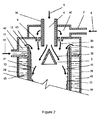
- FIG 2 a more detailed schematic view of the upper section of the cooling equipment is shown.
- vapors to be condensed 5 enter into the equipment through a central duct 4 thermally insulated with an insulation layer 36 .
- the vapors 38 face the flow of a cold gas 6 , which enters through a duct 7 into an upper chamber 40 , which is provided with two or more openings or nozzles 9 to effect the mixture of cold gases 39 and vapors 38 , thus decreasing the temperature thereof, this mixture being conducted to the periphery of the cooling equipment to contact the liquid film 13 through a central diffusion cone 3 .
- the mixture of vapors and gas 41 enters into contact with a cold liquid film 13 at 60°C o less, which can be a biofuel or other liquid 10 that is cooled out of the cooling equipment and enters into the cooling equipment through a duct 11 to form a liquid ring 42 that flows over the annular dam 13 at 43 to form a film that gravitationally flows 13 over the inner wall 44 of the cooling equipment, said walls being provided with an external refrigeration jacket 28 inside which a cooling refrigerating liquid or gas 45 , such as water or the like, flows at a temperature of 60°C or lower.
- a cooling refrigerating liquid or gas 45 such as water or the like
- Vapor from fast pyrolysis of radiata pine sawdust at a temperature of 480°C was cooled in the fast cooling equipment for organic or inorganic vapors of the invention.
- Previously obtained non-condensable pyrolysis gas in a ratio of 4 volumes of gas at 15°C per each volume of vapor at 480°C, and bio-oil obtained from a previous operation in a flow ratio of 1 volume of liquid (bio-oil) per each 20 volumes of pyrolysis vapor were used.
- the cooling equipment had external walls refrigerated with circulating water that entered at 15°C.
- the condensation efficiency of bio-oil vapors (referred to the total condensable fraction) was 96.8%.
Landscapes
- Engineering & Computer Science (AREA)
- Chemical & Material Sciences (AREA)
- Mechanical Engineering (AREA)
- General Engineering & Computer Science (AREA)
- Chemical Kinetics & Catalysis (AREA)
- Combustion & Propulsion (AREA)
- General Chemical & Material Sciences (AREA)
- Oil, Petroleum & Natural Gas (AREA)
- Organic Chemistry (AREA)
- Physics & Mathematics (AREA)
- Thermal Sciences (AREA)
- Vaporization, Distillation, Condensation, Sublimation, And Cold Traps (AREA)
- Production Of Liquid Hydrocarbon Mixture For Refining Petroleum (AREA)
Applications Claiming Priority (2)
| Application Number | Priority Date | Filing Date | Title |
|---|---|---|---|
| CL2009002227A CL2009002227A1 (es) | 2009-12-29 | 2009-12-29 | Equipo de enfriamiento rapido para vapores organicos o inorganicos que comprende: un cuerpo doble conico truncado con camisa externa de refrigeracion; una tapa superior de entrada de vapores y una camara anular con perforaciones para el gas frio; un cono central interno con deflectores; zona inferior de acumulacion de liquidos. |
| PCT/IB2010/055556 WO2011080627A1 (fr) | 2009-12-29 | 2010-12-02 | Équipement de refroidissement rapide pour vapeurs organiques ou inorganiques |
Publications (2)
| Publication Number | Publication Date |
|---|---|
| EP2372320A1 true EP2372320A1 (fr) | 2011-10-05 |
| EP2372320A4 EP2372320A4 (fr) | 2014-03-12 |
Family
ID=44226210
Family Applications (1)
| Application Number | Title | Priority Date | Filing Date |
|---|---|---|---|
| EP10840214.0A Withdrawn EP2372320A4 (fr) | 2009-12-29 | 2010-12-02 | Équipement de refroidissement rapide pour vapeurs organiques ou inorganiques |
Country Status (6)
| Country | Link |
|---|---|
| US (1) | US20120006051A1 (fr) |
| EP (1) | EP2372320A4 (fr) |
| BR (1) | BRPI1006050A2 (fr) |
| CA (1) | CA2748771A1 (fr) |
| CL (1) | CL2009002227A1 (fr) |
| WO (1) | WO2011080627A1 (fr) |
Cited By (2)
| Publication number | Priority date | Publication date | Assignee | Title |
|---|---|---|---|---|
| RU2614897C1 (ru) * | 2015-12-28 | 2017-03-30 | Федеральное государственное бюджетное учреждение науки Институт теплофизики им. С.С. Кутателадзе Сибирского отделения Российской академии наук (ИТ СО РАН) | Конденсатор-сепаратор для двухкомпонентных двухфазных систем |
| TWI732645B (zh) * | 2020-08-05 | 2021-07-01 | 國立臺灣科技大學 | 分離冷卻裝置及應用其的燃料化系統 |
Families Citing this family (5)
| Publication number | Priority date | Publication date | Assignee | Title |
|---|---|---|---|---|
| US9527022B2 (en) | 2012-06-08 | 2016-12-27 | Uop Llc | Method and apparatus for producing pyrolysis oil having improved stability |
| CN110332182A (zh) * | 2019-07-26 | 2019-10-15 | 成都海成远创科技有限公司 | 一种等静压机液压油冷却装置 |
| CN110408800B (zh) * | 2019-08-28 | 2021-08-17 | 谢文最 | 一种钨金属粉末制品用旋转炉尾气回收装置 |
| CN113324431A (zh) * | 2021-05-31 | 2021-08-31 | 山东金太阳设备制造有限公司 | 一种板式煤气冷却器 |
| CN118807240B (zh) * | 2024-07-02 | 2025-09-05 | 中国石油大学(华东) | 一种气动式油雾抽吸分离装置 |
Family Cites Families (11)
| Publication number | Priority date | Publication date | Assignee | Title |
|---|---|---|---|---|
| US2389005A (en) * | 1944-07-14 | 1945-11-13 | Worthington Pump & Mach Corp | Condenser |
| BE576148A (fr) * | 1958-02-26 | |||
| US3131237A (en) * | 1958-11-17 | 1964-04-28 | Jr Theron T Collins | Gas scrubbing apparatus |
| US3212761A (en) * | 1963-01-14 | 1965-10-19 | Chemical Construction Corp | Gas quencher |
| US3353803A (en) * | 1967-05-09 | 1967-11-21 | Chemical Construction Corp | Gas quencher |
| FR2377836A1 (fr) * | 1977-01-25 | 1978-08-18 | Rhone Poulenc Ind | Procede et dispositif pour la mise en contact de produits sous forme de plusieurs phases et separation des produits du melange et application |
| JPS53110967A (en) * | 1977-03-11 | 1978-09-28 | Babcock Hitachi Kk | Device of quencher |
| DE2946102A1 (de) * | 1979-11-15 | 1981-05-27 | Metallgesellschaft Ag, 6000 Frankfurt | Verfahren und vorrichtung zum schwelen von feinkoernigem schwelgut mit heissem, feinkoernigem waermetraegermaterial |
| CN2221763Y (zh) * | 1995-09-07 | 1996-03-06 | 肖德田 | 高效过流汽-水直接热交换器 |
| US5649985A (en) * | 1995-11-29 | 1997-07-22 | Kanken Techno Co., Ltd. | Apparatus for removing harmful substances of exhaust gas discharged from semiconductor manufacturing process |
| DE102007027601A1 (de) * | 2007-06-12 | 2008-12-18 | Uhde Gmbh | Herstellung und Kühlung von gasförmigen Kohlevergasungsprodukten |
-
2009
- 2009-12-29 CL CL2009002227A patent/CL2009002227A1/es unknown
-
2010
- 2010-12-02 WO PCT/IB2010/055556 patent/WO2011080627A1/fr not_active Ceased
- 2010-12-02 CA CA2748771A patent/CA2748771A1/fr not_active Abandoned
- 2010-12-02 US US13/142,969 patent/US20120006051A1/en not_active Abandoned
- 2010-12-02 BR BRPI1006050A patent/BRPI1006050A2/pt not_active Application Discontinuation
- 2010-12-02 EP EP10840214.0A patent/EP2372320A4/fr not_active Withdrawn
Cited By (2)
| Publication number | Priority date | Publication date | Assignee | Title |
|---|---|---|---|---|
| RU2614897C1 (ru) * | 2015-12-28 | 2017-03-30 | Федеральное государственное бюджетное учреждение науки Институт теплофизики им. С.С. Кутателадзе Сибирского отделения Российской академии наук (ИТ СО РАН) | Конденсатор-сепаратор для двухкомпонентных двухфазных систем |
| TWI732645B (zh) * | 2020-08-05 | 2021-07-01 | 國立臺灣科技大學 | 分離冷卻裝置及應用其的燃料化系統 |
Also Published As
| Publication number | Publication date |
|---|---|
| EP2372320A4 (fr) | 2014-03-12 |
| CA2748771A1 (fr) | 2011-07-07 |
| CL2009002227A1 (es) | 2010-04-16 |
| US20120006051A1 (en) | 2012-01-12 |
| WO2011080627A1 (fr) | 2011-07-07 |
| BRPI1006050A2 (pt) | 2016-05-10 |
Similar Documents
| Publication | Publication Date | Title |
|---|---|---|
| EP2372320A1 (fr) | Équipement de refroidissement rapide pour vapeurs organiques ou inorganiques | |
| CA1062643A (fr) | Methode de recuperation de la chaleur d'hydrocarbures de craquage thermique a haute temperature | |
| US11471817B2 (en) | Method for processing plastic waste pyrolysis gas | |
| CA2694352C (fr) | Production d'olefine utilisant une alimentation contenant un condensat et du petrole brut | |
| KR101316141B1 (ko) | 전체 원유 공급 원료를 사용하는 올레핀 제조 | |
| US7981374B2 (en) | Method for processing hydrocarbon pyrolysis effluent | |
| US20100230235A1 (en) | Method For Processing Hydrocarbon Pyrolysis Effluent | |
| US7847136B2 (en) | Device and method for recovering fractional hydrocarbons from recycled plastic fractions and/or oily residues | |
| JP5027660B2 (ja) | 残留油を含む炭化水素原料の熱分解に用いられる蒸気/液体分離装置 | |
| JP2009528426A (ja) | 凝縮液原料を利用したオレフィンの製造 | |
| US4150716A (en) | Method of heat recovery from thermally decomposed high temperature hydrocarbon gas | |
| KR100966962B1 (ko) | 탄화수소 열분해 유출물을 처리하는 방법 | |
| JP2016536375A (ja) | 石油精製塔におけるクラッキングガス流の精製方法 | |
| KR101475068B1 (ko) | 열분해로 유출물의 수냉 방법 및 수냉 장치 | |
| US20110315537A1 (en) | Selective temperature quench and electrostatic recovery of bio-oil fractions | |
| US20070007174A1 (en) | Method for processing hydrocarbon pyrolysis effluent | |
| US7802985B2 (en) | Direct fired heater utilizing particulates as a heat transfer medium | |
| CN210462963U (zh) | 一种可控制蒸汽/烃比的轻烃热裂解用稀释蒸汽发生装置 | |
| US3397251A (en) | Method of producing ethylene and acetylene | |
| JPS61174903A (ja) | 水クエンチ塔 | |
| JPH0542478B2 (fr) |
Legal Events
| Date | Code | Title | Description |
|---|---|---|---|
| PUAI | Public reference made under article 153(3) epc to a published international application that has entered the european phase |
Free format text: ORIGINAL CODE: 0009012 |
|
| 17P | Request for examination filed |
Effective date: 20110630 |
|
| AK | Designated contracting states |
Kind code of ref document: A1 Designated state(s): AL AT BE BG CH CY CZ DE DK EE ES FI FR GB GR HR HU IE IS IT LI LT LU LV MC MK MT NL NO PL PT RO RS SE SI SK SM TR |
|
| DAX | Request for extension of the european patent (deleted) | ||
| A4 | Supplementary search report drawn up and despatched |
Effective date: 20140210 |
|
| RIC1 | Information provided on ipc code assigned before grant |
Ipc: G01G 9/00 20060101AFI20140204BHEP Ipc: B01D 5/00 20060101ALI20140204BHEP Ipc: C10J 3/82 20060101ALI20140204BHEP Ipc: C10K 1/04 20060101ALI20140204BHEP Ipc: F28C 3/08 20060101ALI20140204BHEP |
|
| STAA | Information on the status of an ep patent application or granted ep patent |
Free format text: STATUS: THE APPLICATION IS DEEMED TO BE WITHDRAWN |
|
| 18D | Application deemed to be withdrawn |
Effective date: 20140910 |