EP2372333A1 - Niveau de contrôle et procédé de contrôle de systèmes dynamiques de conduite et/ou de leurs composants - Google Patents
Niveau de contrôle et procédé de contrôle de systèmes dynamiques de conduite et/ou de leurs composants Download PDFInfo
- Publication number
- EP2372333A1 EP2372333A1 EP11160713A EP11160713A EP2372333A1 EP 2372333 A1 EP2372333 A1 EP 2372333A1 EP 11160713 A EP11160713 A EP 11160713A EP 11160713 A EP11160713 A EP 11160713A EP 2372333 A1 EP2372333 A1 EP 2372333A1
- Authority
- EP
- European Patent Office
- Prior art keywords
- vehicle
- test stand
- motor vehicle
- rollers
- double roller
- Prior art date
- Legal status (The legal status is an assumption and is not a legal conclusion. Google has not performed a legal analysis and makes no representation as to the accuracy of the status listed.)
- Granted
Links
Images
Classifications
-
- G—PHYSICS
- G01—MEASURING; TESTING
- G01M—TESTING STATIC OR DYNAMIC BALANCE OF MACHINES OR STRUCTURES; TESTING OF STRUCTURES OR APPARATUS, NOT OTHERWISE PROVIDED FOR
- G01M17/00—Testing of vehicles
- G01M17/007—Wheeled or endless-tracked vehicles
- G01M17/0072—Wheeled or endless-tracked vehicles the wheels of the vehicle co-operating with rotatable rolls
- G01M17/0074—Details, e.g. roller construction, vehicle restraining devices
Definitions
- the invention relates to a test stand for a motor vehicle having a first Vorderachsendoppelrollensatz and a second Vorderachsendoppelrollensatz and a first Schuachsendoppelrollensatz and a second Schuachsendoppelrollensatz, and a method for checking driving dynamics systems and / or their components.
- test benches for carrying out such a method are mainly used for driving dynamics tests of a motor vehicle
- the test stands usually have a very complicated structure to test vehicle dynamics control of a motor vehicle.
- the Vorderachsendoppelrollen algorithms on which the front wheels of the motor vehicle to be tested can be positioned, and the Schuachsendoppelrollen algorithms on which the rear wheels of the motor vehicle to be tested can be positioned here are usually arranged stationary on a platform, wherein the platform itself is movable. In order to cover and simulate the entire control range, many degrees of freedom and variables are usually necessary for this, so that usually the entire platform on which the VorderachsendoppelrollenA and SchuachsendoppelrollenA are arranged, can swing, tilt and twist.
- both the Schuachsendoppelrollen algorithms and the VorderachsendoppelrollenA be pivoted simultaneously to each other, so that a motor vehicle arranged on the test bench is tilted or pivoted both to its rear area and its front area.
- the entire test bench has a very complex structure and a very complex scheme.
- the object of the invention is therefore to provide a test stand and a method for checking vehicle dynamics systems and / or their components are available, which are characterized by a simplified structure for a driving dynamics test.
- the test stand for a motor vehicle comprises a first two-roller Vorderachsendoppelrollensatz and a second two-roller Vorderachsendoppelrollensatz and a first two rollers Schuachsendoppelrollensatz and a second two-roller Schuachsendoppelrollensatz, wherein the first Schuachsendrollollatz and the second Schuachsendrollollatz relative to the first Vorderachsendoppelrollensatz and / or the second Vorderachsendoppelrollensatz is mounted in a plane pivotable and / or displaceable.
- This test stand according to the invention for testing the effectiveness of the vehicle dynamics control of a motor vehicle is characterized in that no longer an entire platform on which both the VorderachsendoppelrollenA and the SchuachsendoppelrollenA are arranged, must be pivoted, but only a laterally directed pivoting movement of Schuachsendoppelrollen algorithms, wherein the pivoting movement of the SchuachsendoppelrollenA in a plane to each other, which means that the Schuachsendoppelrollenadapter.
- the first and second Schuachsendrollollensatz is relative to the first Vorderachsendoppelrollensatz and / or the second Vorderachsendoppelrollenthesis in a plane pivotally and / or displaceable, in particular laterally displaceable stored.
- the first and second Schuachsendoppelrollensatz may be designed to be pivotable for the execution of arcuate paths, wherein the first and second Schuachsendoppelrollensatz, for example, in or on arcuate paths is displaceable or pivotable.
- the pivoting movement itself is preferably carried out at a high speed.
- the pivoting movement can be composed of a first phase, the acceleration phase, with a freely adjustable acceleration, a second phase with a freely adjustable, uniform speed and a third phase, the deceleration phase, with a freely adjustable delay, wherein the pivoting movement, for example, very fast or can be made as slow as you like. Furthermore, the pivoting movement can be stopped in any position, in particular before reaching an end position.
- the SchuachsendoppelrollenA can be pivoted relative to the first Vorderachsendoppelrollensatz and / or the second Vorderachsendoppelrollensatz and / or moved, so that the rear wheels of the motor vehicle, which are arranged on the Schuachsendoppelrollen algorithmsn are pivoted relative to the arranged on the Vorderachsendoppelrollen algorithmsn front wheels and / or moved can, whereby it is thereby possible to simulate a lateral breakout of the rear portion of the motor vehicle.
- all wheels of the motor vehicle are driven via the VorderachsendoppelrollenA and the SchuachsendoppelrollenA during the pivoting of SchuachsendoppelrollenA so that the wheels rotate, which corresponds to a driving condition of a so-called "rolling".
- the rear portion of the motor vehicle by pivoting or deflecting the Schuachsendoppelrollen algorithms relative to the VorderachsendoppelrollenA, so it is possible to effect the vehicle with deflected front wheels to impose a lateral acceleration and / or yaw rate.
- the automotive sensor system diagnoses critical vehicle dynamics values and an electronic stability program (ESP) control system can intervene. As a result, the simulation of an oversteering spinning process is possible, in particular to be able to determine the functionality of the ESP control system of the motor vehicle to be tested.
- ESP electronic stability program
- the first Schuachsendoppelrollensatz on a first spinner and the second Schuachsendrollollatz are arranged on a second spinner, wherein the first spinner and the second spinner are connected to each other via a coupling element.
- a pivoting movement of the Schuachsendoppelrollen engines is achieved.
- Both Schuachsendoppelrollenadapt have separate spinners on.
- Each of the two centrifugal devices preferably rolls over a steel plate arranged below the centrifugal device, wherein the centrifugal device is preferably movably mounted on the steel plate via steel balls.
- the coupling element is arranged between the two Schuachsendoppelrollen algorithmsn, wherein the coupling element is fastened with its first end to the first Schuachsendoppelrollensatz and is fastened with its first end opposite the second end of the second Schuachsendoppelrollensatz.
- the coupling element is fixed equidistant to the two Schuachsendoppelrollen algorithmsn, the distance between the two Schuachsendoppelrollen algorithmsn and the orientation of the two Schuachsendoppelrollen algorithmsn each other is not changed in a pivoting of the Schuachsendoppelrollen algorithmsn.
- a pivoting arm is preferably provided for carrying out a pivoting movement of the first Schuachsendollollensatzes and the second Schuachsendollrollensatzes, wherein the pivot arm is pivotally mounted with a first end to the coupling element and fixed with a first end opposite the second end fixed to the test stand, in particular the Swivel arm along its longitudinal axis in its length is variable and the pivot arm is rotatably disposed about its second end.
- the swivel arm is preferably arranged with its first end along the longitudinal axis of the coupling element centered on the coupling element, wherein the swivel arm is preferably aligned with its longitudinal axis vertically to the longitudinal axis of the coupling element.
- the first spin device and / or the second spin device have locking means.
- a return means for moving together the adjustable length of the pivot arm and a locking means for detecting the articulated mounting of the pivot arm is provided on the coupling element, wherein a preferably rectangular locking of the pivot arm on the coupling element by means of locking, for example by means of a centering hook, always outside the test condition " Panning "takes place.
- the locking means are released, so that no locking of the pivot arm is provided on the coupling element.
- the swivel arm by means of a drive, preferably by means of a piston of a hydraulic cylinder drivable, in particular a drive movement of the drive, in particular the piston of the hydraulic cylinder via a PLC-controlled hydraulic proportional valve can be triggered and by means of a PLC program in its movement and the degree of acceleration is controllable.
- the hydraulic cylinder with the piston therein is preferably rigidly attached to the pivot arm along the longitudinal side of the pivot arm. If the piston of the hydraulic cylinder is driven, a force is applied via the hydraulic cylinder to the swivel arm, by means of which a rotational movement of the swivel arm and thus of the coupling arm attached to the swivel arm is effected.
- the hydraulic cylinder with the piston may preferably be connected via a line system and a proportional valve with a large bladder accumulator. The bladder accumulator is kept at a certain pressure level continuously.
- the required hydraulic energy can be made available for a preferably explosive drive movement of the swivel arm, or it can be delivered throttled for swiveling at a low speed.
- the pivoting movement of the test stand can be effected in its movement, direction of movement and / or acceleration by means of the PLC controlled by the drive, this drive is preferably realized by pressurization of the piston of the hydraulic cylinder, which can be triggered by means of a PLC-controlled hydraulic proportional valve is.
- the PLC programmable logic controller
- the sequence of the pivoting movement and thus freely programmed the spinning process. Time sequences, the size of the acceleration, the spin speed and the deceleration process of the spin movement can be varied. This makes it possible to adapt to the control characteristics of different vehicle types or to the investigation of other vehicle systems.
- the first Vorderachsendoppelrollensatz is arranged during a pivoting movement of the first Schuachsendoppelrollensatzes and the second Schuachsendoppelrollensatzes in a fixed position on the test bed, in particular the second Vorderachsendoppelrollensatz during a pivoting movement of the first Schuachsendoppelrollensatzes and the second Schuachsendrollollatz in the longitudinal direction of the test stand is arranged on the test bench.
- the first Vorderachsendoppelrollensatz is preferably not moved in a pivoting movement of the Schuachsendoppelrollenastas, but remains at the position which was chosen when setting the test stand to the wheelbase of the vehicle to be tested.
- the entire motor vehicle can thus be pivoted about the steering knuckle pin or virtual pivot point in accordance with the steering geometry of the front wheel arranged on the first front axle double roller set.
- the second Vorderachsendoppelrollensatz is arranged during a pivoting movement of the first Schuachsendoppelrollensatzes and the second Schuachsendrollollatz in the longitudinal direction of the test bed movable on the test bed, the second Vorderachsendoppelrollensatz make during the pivoting movement of the Schuachsendoppelrollenesthesiaados a compensating movement to prevent the motor vehicle during the pivoting movement the twin roller sets leaves.
- the second Vorderachsendoppelrollensatz is preferably in the longitudinal direction of the test stand in the direction of the arranged behind him Deutschenachsendoppelrollensatzes movable.
- the friction work performed during the longitudinal movement of the second front axle double roller set is achieved by a displacement mechanism, preferably with hydraulic auxiliary energy applied.
- the movement itself is not actively regulated by the displacement mechanism, but inevitably results from the specific vehicle geometry.
- Each vehicle thus determines how the sequence of movements for the second Vorderachsendoppelrollensatz must be made in dependence on the movement of the centrifugal devices of Deutschenachsendoppelrollenasta.
- the rollers of the first Schuachsendrollollensatzes and / or the second Schuachsendoppelrollensatzes and the roles of the first Vorderachsendoppelrollensatzes and / or the second Vorderachsendoppelrollensatzes are variably adjustable in their direction of rotation and / or in their speed, in particular all roles always rotate in the same direction
- the rotational speed of the rollers of the first and second Schuachsendrollollensatzes is decoupled to the rotational speed of the rollers of the first and the second Vorderachsendoppelrollensatzes.
- the direction of rotation and the number of revolutions of the rollers of the double roller sets can be freely selected by axle and adapted to the test to be carried out on the vehicle accordingly.
- the rotational speed of the rollers of the VorderachsendoppelrollenA can be preferably set and controlled independently of the direction of rotation and the rotational speed of the rollers of the SchuachsendoppelrollenA. Decoupled here means that the speed of the rollers of the SchuachsendoppelrollenA is independent of the speed of the roles of VorderachsendoppelrollenA adjustable. With this setting it is possible to detect error reactions of the sensors. But it is also possible that the rotational speed of the rollers of the SchuachsendoppelrollenA synchronously coupled to the rotational speed of the roles of VorderachsendoppelrollenA or tracked in a maser-slave mode each other.
- rollers of the first and second Schuachsendrollollatz and the roles of the first and second Vorderachsendoppelrollensatzes each axle via at least one engine of the test stand are driven (“motor drive”) or these roles only by the wheels of the test vehicle can be driven (“regenerative drive”), wherein in particular for driving the rollers of the first and second Vorderachsendollrollensatzes a common central drive is provided, in particular a first switchable clutch for separating the first and the second Vorderachsendoppelrollensatzes and / or a second switchable clutch for Separating the first and second Schuachsendrollrollensatzes is provided.
- the common central drive makes it possible to provide the required drive power in the motor drive via exactly one drive without the need for multiple drives, so that the equipment required for the test stand is reduced and the manufacturing costs and maintenance costs are reduced.
- the common central drive enables the simulation of driving resistances, in which an electrical power output takes place at an energy level that can be used without major transformation effort and / or fed into an existing power grid.
- the first switchable coupling and / or second switchable coupling roller sets can be separated from the central drive, wherein the first switchable clutch and / or the second switchable clutch during operation, for example, separately or together, are switchable.
- first and the second Vorderachsendrollollatz and / or the first and the second Schuachsendrollollatz each having at least one free-running role, in particular in each case at least one free-running role having a pulse generator for speed measurement.
- Each double roller set can have a driven roller and a free-running roller.
- the driven roller, or drive roller for example, be driven directly or via a propeller shaft.
- the free-running reel, or freewheel is driven or taken over the wheel of the motor vehicle which contacts the free-running reel. All freewheeling rollers can do this Pulse, for example in the form of a gear, which allows the detection of the rotational speed of the respective free-running role and thus the associated wheel of the motor vehicle.
- the course of the respective wheel speed, the speed curve can be detected by a respectively assigned speed sensor.
- a data adapter for receiving and / or storing signals from vehicle dynamics systems and / or vehicle control devices.
- the data adapter may include a memory unit for storing acquired data / control signals.
- the data adapter is designed for recording control signals of the vehicle dynamics system and / or further control devices of the motor vehicle, directly connectable to the vehicle dynamics system or to a data bus system of the motor vehicle.
- the data adapter can detect signals between the controllers, for example by means of special software, and store.
- the data adapter can be connected to an evaluation system and / or a control system, for example, of the test stand.
- the detected control signals of the control units of the motor vehicle allow the precise setting of a specific, already detected, driving condition or driving maneuver of the motor vehicle, which is repeatably adjustable by means of the test stand according to the invention.
- the invention further relates to a method for checking vehicle dynamics systems and / or components thereof with the aid of a test stand having a first rear axle double roller set and a second rear axle twin roller set for receiving the rear wheels of a motor vehicle.
- the test bench can be designed and developed as described above.
- a motor vehicle is mounted on the test bench, wherein the rear wheels of the motor vehicle are respectively connected to the first Schuachsendoppelrollensatz and the second Schuachsendoppelrollensatz.
- the first rear axle double roller set and the second Schuachsendoppelrollensatzes suddenly pivoted, and recorded output signals of vehicle dynamics systems, such as an ESP system, and / or speed characteristics of the individual wheels of the motor vehicle and evaluated for checking the operation of the vehicle dynamics system.
- vehicle dynamics systems such as an ESP system
- the generation of output signals of the vehicle dynamics system or of control interventions of the vehicle dynamics system, for example changes in the rotational speed characteristics of the wheels, can take place by acting on the test vehicle on the motor vehicle.
- the motor vehicle preferably in its center of gravity, for example, a lateral acceleration and / or a yaw rate can be impressed, whereby the motor vehicle, in particular the rear of the motor vehicle, performs a centrifugal movement. Since essentially only the SchuachsendoppelrollenA need to be pivoted, for example, to simulate a skid of the motor vehicle, the remaining components of the test stand remain essentially immobile or can be pivoted only slightly compared to the Deutschenachsendoppelrollen algorithmsn.
- the set program is performed in the simulation of a driving condition without control signals of the vehicle dynamics system or the recorded measurement results or externally stored data are linked to the test stand to influence the course of the experiment.
- the implementation of the simulation and the acquisition of the measured data is independent of, for example, recorded and recorded control signals of the vehicle dynamics system.
- the control signals of the vehicle dynamics system can be detected, for example, with a data adapter, which can be connected to the vehicle dynamics system directly or via a data bus system of the motor vehicle.
- the data adapter can be connected to an evaluation system or control system for evaluation.
- the speed curves of the wheels of the motor vehicle are detected, the course of the simulation is unaffected.
- the function of the vehicle dynamics system of the motor vehicle can be detected directly, for example by detecting the speed curve of all wheels.
- a lateral pivoting movement of the first and second Schuachsendrollollensatzes executed at the beginning of the verification process by an explosive release of the main energy while the output signals of the vehicle dynamics systems and / or their components time resolved, preferably via the vehicle's own bus system, electronically recorded and / or the movement of the vehicle wheels,
- This also makes it possible to simulate particularly critical ejection situations of the motor vehicle and also to check the reaction of the vehicle dynamics systems in extreme situations.
- the compensating movement of the first and second Schuachsendrollollensatzes causes in the longitudinal direction of the pivot arm, in particular at the moment of the beginning of the pivoting movement, the rotation of the rollers of the first and second Vorderachsendoppelrollensatzes (10, 12) and the rotation of the rollers of the first and second Schuachsendrollollatz (14, 16) are each decoupled from each other.
- the pivoting of the motor vehicle takes place about one of the Vorderachsendoppelrollen algorithms as a center of rotation, so that only for each other Vorderachsendoppelrollensatz the first auxiliary drive is required.
- the energy required for the required during the pivoting movement of the motor vehicle compensatory movements can be provided in the immediate vicinity of the respective vehicle, so that determined by a simple design measure the vehicle geometry the required travel paths independently.
- the speed of the wheel and / or the rollers for example, the first Vorderachsendoppelrollensatzes or the first Schuachsendoppelrollensatzes run regardless of the speed of the wheel and / or the rollers of the second Vorderachsendoppelrollensatzes or the second Schuachsendrollollatz.
- the speed curve is independent of the central drive, which can drive the rollers.
- the review of driving dynamics systems begins with the pivoting movement of the first and second Schuachsendrollollatz from the initial position of the swing arm and at the same time a power supply of the first auxiliary drive, preferably the first piston with auxiliary cylinder, and the second auxiliary drive, preferably the second piston with auxiliary cylinder released and can be done until the pivot arm reaches its end position, thereby ending the review of vehicle dynamics systems and also the respective power supply for the first and the second auxiliary drive is terminated.
- defined initial conditions and defined final conditions for carrying out the verification process are given, which avoids unnecessary energy consumption for the auxiliary drives.
- the pivoting of the swivel arm in its end position can be done, for example, with pauses, a temporary stop the pivoting movement of the swivel arm.
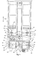
- Fig. 1 an inventive test stand is shown schematically.
- the test stand has a first two-roller Vorderachsendoppelrollensatz 10 and a second two-roller Vorderachsendoppelrollensatz 12, on each of which the front wheels of a motor vehicle, not shown, can be positioned.
- the test stand has a first two-roller rear axle double roller set 14 and a second two-roller rear axle double roller set 16 on which the rear wheels of a motor vehicle can be positioned.
- the VorderachsendoppelrollenA 10, 12 are arranged on thrust racks with lifting thresholds 18 arranged thereon, by means of which the Vorderachsendoppelrollen algorithms 10, 12 in the longitudinal direction 48 of the test stand are displaced.
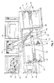
- the two Schuachsendoppelrollen algorithms 14, 16 are each arranged on a spinner 20, 22, by means of which the Schuachsendoppelrollen algorithms 14, 16 pivoted relative to the Vorderachsendoppelrollen algorithms 10, 12, in particular laterally pivoted, and / or displaced, in particular laterally displaced, can, as in Fig. 2 shown in order to simulate a spinning of the rear of a motor vehicle.
- the two centrifugal devices 20, 22 are preferably arranged on the test bench that they can roll over a steel plate by the spinners 20, 22 are preferably mounted on four or more steel balls, by means of which the spinners 20, 22 respectively over the Roll steel plates.
- the two centrifugal devices 20, 22 are connected to each other by means of a coupling element 24.
- the coupling element 24 is designed in the form of a spatial construction, wherein the coupling element 24 is connected with its first end 26, for example via a bolt connection, with the first spinner 20. With its second end 28, the coupling element 24, for example via a bolt connection, connected to the second spinner 22.
- a pivot arm 30 is arranged with its first end 32 at a lockable pivot point P3 of the coupling element 24.
- the coupling element 24 can perform no pendulum motion about the pivot point P3.
- the lock is released, so that the coupling element 24 can oscillate about the pivot point P3.
- the longitudinal axis of the coupling element 24 is preferably arranged perpendicular to the longitudinal axis of the pivot arm 30, as in Fig. 1 can be seen.
- normal run tests may be performed in motor or generator mode, preferably up to a speed of the wheels on the front axle twin pulley sets 10, 12 and the rear axle twin pulley sets 14, 16 of up to 120 km / h.
- the rollers of the first and second Schuachsendoppelrollensatzes 14, 16 and the rollers of the first and second Vorderachsendoppelrollensatzes 10, 12 are each axles via a motor of the test stand driven and / or by the wheels of the vehicle to be tested.
- a first switchable clutch 54 for separating the first and the second Vorderachsendoppelrollensatzes 10, 12 and a second shiftable clutch 56 for separating the first and the second Schuachsendoppelrollensatzes 14, 16 is provided.
- the first shiftable clutch 54 and the second shiftable clutch 56 can be operated during operation.
- the pivot arm 30 is fixedly attached to the test stand via its second end 34 at the point P1, so that the pivot arm 30 has a like in Fig. 2 shown rotational movement about the point P1 can perform.
- the Schuachsendoppelrollen algorithms 14, 16 are formed pivotable about P1 and / or P3.
- the pivot arm 30 is configured such that it is variable in its length, as indicated by arrow 36.
- the swivel arm 30, in particular during its rotational movement independently make an additional length compensation of the distance between the points P1 and P3. This ensures that the rear wheels of the vehicle to be tested during the pivoting movement exactly each of the circular path can describe (about a virtual pivot point of the steering geometry on the right-bound front wheel), which makes necessary from the specific vehicle geometry.
- the pivot arm In order to initiate a rotational movement of the pivot arm 30, the pivot arm is driven by a piston of a hydraulic cylinder 38.
- the impressed by the piston of the hydraulic cylinder 38 on the pivot arm 30 force is transmitted in the form of a lateral acceleration and yaw rate to the motor vehicle to be tested.
- the hydraulic cylinder 38 is fixed to the swing arm 30 between the first end 32 and the second end 34 along the longitudinal side of the swing arm 30.
- the hydraulic cylinder 38 is fixed at a point P2 fixed to the test stand, wherein the hydraulic cylinder 38 is articulated about the point P2 to perform a pivoting movement about the point P2 can.
- the hydraulic cylinder 38 is preferably fastened with its longitudinal axis at an angle ⁇ 90 ° to the longitudinal axis of the pivot arm 30 on the pivot arm 30.
- Vorderachsendoppelrollen algorithms 10, 12 When entering a motor vehicle on the test bench are preferably the Vorderachsendoppelrollenwith 10, 12 at the smallest possible distance to the Schuachsendoppelrollen algorithmsn 14, 16.
- the motor vehicle moves under its own power with its front wheels first on the Schuachsendoppelrollen algorithms 14, 16 and then up to the lifting thresholds 18th
- the lifting thresholds 18 are then lowered, whereby the front wheels or the front axle of the motor vehicle in the longitudinal direction of the motor vehicle by the action of Vorderachsendoppelrollen algorithms 10, 12 can be fixed.
- the motor vehicle can be additionally secured in the longitudinal direction by each wheel two additional runners 42 are brought to the tire treads.
- a lateral guidance of the wheels can take place via in each case preferably two to four run-up rollers 44 which are brought into contact with the tire flanks of the wheel, preferably as cone-shaped run-up rollers.
- the Schuachsendoppelrollen algorithms 14, 16 by means of the spinners 20, 22 in a plane preferably swung laterally from the starting position in the pivot position and / or moved, such as this in Fig. 2 is shown.
- the wheels of the motor vehicle are preferably brought by the Vorderachsendoppelrollen algorithms 10, 12 and by the Schuachsendoppelrollen algorithms 14, 16 to a preselected speed, so that they to rotate, whereby a driving state of the "rolling out" can be simulated.
- the vehicle sensor system will produce critical driving dynamics values diagnosed and the control system, in particular the ESP, intervenes. As a result, a simulation of an oversteering spinning process is possible. In this case, it can be checked in particular whether an independent intervention of the brake system takes place in order to be able to check the functionality of the ESP of the motor vehicle.
- the complete motor vehicle turns around the kingpin (or a virtual axis of rotation according to concrete steering geometry) of one of the front wheels when the rear area breaks out.
- the thrust frame remains one of the Vorderachsendoppelrollen algorithms 10, 12, in the in Fig. 2 shown example, the first Vorderachsdoppelrollensatz 10, fixed in its experimental position, which was set when setting the wheelbase.
- the other front wheel, about which the motor vehicle is not rotated, describes during the pivoting movement a slight circular path to the rear in the direction of the initial position of Deutschenachsendoppelrollen algorithms 14, 16.
- the occurring very small transverse movement of the front wheel is preferably not structurally intercepted by the test, but an automatic Compensation of the wheel to double roller set 12 left (drifting, walking).
- the case also occurring change in position of Vorderachsendoppelrollensatzes 12 to the initial position of the Schuachsendoppelrollensatzes 16 is compensated for, that these Vorderachsendoppelrollen 12 are mounted separately longitudinally displaceable in the associated thrust frame.
- a first auxiliary drive 50 with hydraulic cylinder can in this case track the front axle double roller set 12 of the movement of the corresponding front wheel.
- the deflection of the centrifugal devices 20, 22 preferably takes place via a PLC-controlled hydraulic proportional valve 46, which acts on the piston of the hydraulic cylinder 38.
- a large bladder accumulator which can be kept continuously at a certain pressure level, makes the required hydraulic energy exploded.
- the sequence of the spinning process or the swiveling movement can be freely programmed. Timing, the amount of acceleration, the spin speed and the deceleration process can be varied. This makes it possible to adapt to the control characteristics of different vehicle types.
- the test stand is preferably constructed such that the spin mechanism itself ensures only the necessary movements for the hinge point P3.
- the concrete movement curves of the centrifugal devices 20, 22 are preferably not programmed, whereby the complexity of the test stand can be reduced.
- the corresponding motor vehicle with its vehicle geometry is preferably used in each case like a template in order to be able to execute exactly the pivoting movement of the centrifugal devices 20, 22 or the rear axle double roller sets 14, 16 required for this motor vehicle.
- the hydraulic cylinder 38 is designed such that it allows both an acceleration of the pivot arm 30 to trigger the pivoting movement as well as a delay or damping of the pivot arm 30 for braking the pivoting movement.
- the deceleration can additionally be supplemented by further damping elements and / or by an emergency catch device.
- the motor vehicle After completion of the pivoting movement or the spinning process, the motor vehicle is preferably moved back to the starting position with a significantly slower speed than during the pivoting movement from the pivoting position back.
- the starter rollers 44 can additionally support this process.
- a mechanical locking of the centrifugal mechanism for example, by the locking of the pivot arm 30 are detected again done so that a defined starting position can be made available for retry.
- All processes can preferably take place via a control unit of the test stand, so that operation of the process by a test person is no longer necessary. Subjective influences by the operator or a test driver can thereby be excluded.
Landscapes
- Physics & Mathematics (AREA)
- General Physics & Mathematics (AREA)
- Testing Of Devices, Machine Parts, Or Other Structures Thereof (AREA)
- Vehicle Body Suspensions (AREA)
- Arrangement And Driving Of Transmission Devices (AREA)
Applications Claiming Priority (1)
| Application Number | Priority Date | Filing Date | Title |
|---|---|---|---|
| DE201010013866 DE102010013866A1 (de) | 2010-04-01 | 2010-04-01 | Prüfstand und Verfahren zum Überprüfen von Fahrdynamiksystemen und/oder deren Komponenten |
Publications (2)
| Publication Number | Publication Date |
|---|---|
| EP2372333A1 true EP2372333A1 (fr) | 2011-10-05 |
| EP2372333B1 EP2372333B1 (fr) | 2016-10-26 |
Family
ID=44224839
Family Applications (1)
| Application Number | Title | Priority Date | Filing Date |
|---|---|---|---|
| EP11160713.1A Active EP2372333B1 (fr) | 2010-04-01 | 2011-03-31 | Niveau de contrôle et procédé de contrôle de systèmes dynamiques de conduite et/ou de leurs composants |
Country Status (3)
| Country | Link |
|---|---|
| EP (1) | EP2372333B1 (fr) |
| DE (1) | DE102010013866A1 (fr) |
| ES (1) | ES2612122T3 (fr) |
Cited By (3)
| Publication number | Priority date | Publication date | Assignee | Title |
|---|---|---|---|---|
| EP2677293A1 (fr) * | 2012-06-20 | 2013-12-25 | Jens Mehnert | Système de contrôle et procédé de contrôle d'un véhicule automobile |
| CN109883727A (zh) * | 2019-03-07 | 2019-06-14 | 唐山百川智能机器股份有限公司 | 便携式车辆稳定检测系统 |
| CN112649136A (zh) * | 2019-10-11 | 2021-04-13 | 独立测试服务中心 | 用于测量作用于物体的力的组件 |
Citations (1)
| Publication number | Priority date | Publication date | Assignee | Title |
|---|---|---|---|---|
| EP1394527A1 (fr) * | 2001-03-15 | 2004-03-03 | Honda Giken Kogyo Kabushiki Kaisha | Procede de mesure d'un taux d'ecoulement unilateral de vehicules |
Family Cites Families (5)
| Publication number | Priority date | Publication date | Assignee | Title |
|---|---|---|---|---|
| GB409077A (en) * | 1932-12-24 | 1934-04-26 | Heenan & Froude Ltd | Improvements in devices for testing self propelled vehicles |
| US4567667A (en) * | 1984-01-24 | 1986-02-04 | Honda Giken Kogyo Kabushikikaisha | Method and apparatus for measuring the inclination of the wheels of an automobile |
| US5111685A (en) * | 1989-12-20 | 1992-05-12 | Mts Systems Corporation | Roadway simulator restraint |
| JP2588982B2 (ja) * | 1990-02-13 | 1997-03-12 | 本田技研工業株式会社 | 車輪検査方法及び装置 |
| JP4240054B2 (ja) * | 2006-04-24 | 2009-03-18 | トヨタ自動車株式会社 | 車両正対装置および車両正対方法 |
-
2010
- 2010-04-01 DE DE201010013866 patent/DE102010013866A1/de not_active Ceased
-
2011
- 2011-03-31 EP EP11160713.1A patent/EP2372333B1/fr active Active
- 2011-03-31 ES ES11160713.1T patent/ES2612122T3/es active Active
Patent Citations (1)
| Publication number | Priority date | Publication date | Assignee | Title |
|---|---|---|---|---|
| EP1394527A1 (fr) * | 2001-03-15 | 2004-03-03 | Honda Giken Kogyo Kabushiki Kaisha | Procede de mesure d'un taux d'ecoulement unilateral de vehicules |
Cited By (3)
| Publication number | Priority date | Publication date | Assignee | Title |
|---|---|---|---|---|
| EP2677293A1 (fr) * | 2012-06-20 | 2013-12-25 | Jens Mehnert | Système de contrôle et procédé de contrôle d'un véhicule automobile |
| CN109883727A (zh) * | 2019-03-07 | 2019-06-14 | 唐山百川智能机器股份有限公司 | 便携式车辆稳定检测系统 |
| CN112649136A (zh) * | 2019-10-11 | 2021-04-13 | 独立测试服务中心 | 用于测量作用于物体的力的组件 |
Also Published As
| Publication number | Publication date |
|---|---|
| EP2372333B1 (fr) | 2016-10-26 |
| ES2612122T3 (es) | 2017-05-12 |
| DE102010013866A1 (de) | 2011-10-06 |
Similar Documents
| Publication | Publication Date | Title |
|---|---|---|
| EP3026416B1 (fr) | Dispositif de verification fonctionnelle de systemes de vehicule | |
| DE60112938T2 (de) | Schleppfahrzeug für flugzeuge und griff- und hebevorrichtung dafür | |
| DE102010034850B4 (de) | Straßensimulationsprüfstand | |
| EP2708489B1 (fr) | Elévateur de véhicule | |
| DE10022355C2 (de) | Rollenprüfstand | |
| EP2677293B1 (fr) | Système de contrôle et procédé de contrôle d'un véhicule automobile | |
| DE19736328A1 (de) | Einrichtung und Verfahren zur Steuerung von Unfallschutz-Auslöseeinrichtungen in Kraftfahrzeugen | |
| DE102014002526B4 (de) | Kollisionsprüfsystem und Verfahren zum Betreiben eines Kollisionsprüfsystems | |
| EP2899101A1 (fr) | Pivot central avec capteur | |
| DE4037384A1 (de) | Verfahren und vorrichtung zum messen und justieren der ausrichtung der raeder eines kraftfahrzeuges | |
| DE112021001905T5 (de) | Fahrzeugtestsystem, lenkreaktionskraft-eingabevorrichtung und verfahren zum auswerten einer lenkfunktion | |
| EP2069741A2 (fr) | Dispositif et procede de determination des parametres d'inertie d'un corps | |
| EP3515796B1 (fr) | Procédé permettant de détecter et/ou de commander une opération d'attelage entre un véhicule tracteur et une remorque de véhicule | |
| EP2372333B1 (fr) | Niveau de contrôle et procédé de contrôle de systèmes dynamiques de conduite et/ou de leurs composants | |
| DE2217702B1 (de) | Regelanordnung für eine Prüf anlage zur Prüfung eines Prüflings mit beweglichen Elementen, insbesondere zur Prüfung von Kraftfahrzeugachsen | |
| DD281655A5 (de) | Verfahren und einrichtung zum feststellen und einstellen der lage von laufwerken | |
| DE3841248A1 (de) | Verfahren und vorrichtung zur untersuchung der bremsen von fahrzeugen, insbesondere solchen mit allradantrieb bzw. antiblockiersystem | |
| DE60020021T2 (de) | Radausrichtungsvorrichtung | |
| EP0884560A2 (fr) | Procédé et dispositif de contrÔle des pneus | |
| DE2518850A1 (de) | Verfahren und vorrichtung zur pruefung der bremsen von kraftfahrzeugen mit mehreren gleichzeitig angetriebenen achsen | |
| DE69516088T2 (de) | Verfahren und Vorrichtung zur Regelung des Anhängerbremsens | |
| EP3182088B1 (fr) | Procédé de contrôle de fonctionnement de plaques flottantes faisant partie intégrante d'un banc d'essai de véhicule | |
| EP2166332A2 (fr) | Procédé et dispositif destinés au guidage d'une trajectoire de véhicule | |
| EP4728256A1 (fr) | Ensemble rouleau, banc d'essai de véhicule comprenant au moins un ensemble rouleau, et procédé de fonctionnement d'un tel banc d'essai de véhicule | |
| EP4568871A1 (fr) | Procédé de fonctionnement d'un véhicule automobile, en particulier d'un véhicule automobile de tourisme, et véhicules automobiles |
Legal Events
| Date | Code | Title | Description |
|---|---|---|---|
| PUAI | Public reference made under article 153(3) epc to a published international application that has entered the european phase |
Free format text: ORIGINAL CODE: 0009012 |
|
| AK | Designated contracting states |
Kind code of ref document: A1 Designated state(s): AL AT BE BG CH CY CZ DE DK EE ES FI FR GB GR HR HU IE IS IT LI LT LU LV MC MK MT NL NO PL PT RO RS SE SI SK SM TR |
|
| AX | Request for extension of the european patent |
Extension state: BA ME |
|
| 17P | Request for examination filed |
Effective date: 20120404 |
|
| 17Q | First examination report despatched |
Effective date: 20131107 |
|
| GRAP | Despatch of communication of intention to grant a patent |
Free format text: ORIGINAL CODE: EPIDOSNIGR1 |
|
| INTG | Intention to grant announced |
Effective date: 20150914 |
|
| GRAJ | Information related to disapproval of communication of intention to grant by the applicant or resumption of examination proceedings by the epo deleted |
Free format text: ORIGINAL CODE: EPIDOSDIGR1 |
|
| GRAP | Despatch of communication of intention to grant a patent |
Free format text: ORIGINAL CODE: EPIDOSNIGR1 |
|
| INTG | Intention to grant announced |
Effective date: 20160520 |
|
| GRAS | Grant fee paid |
Free format text: ORIGINAL CODE: EPIDOSNIGR3 |
|
| GRAA | (expected) grant |
Free format text: ORIGINAL CODE: 0009210 |
|
| AK | Designated contracting states |
Kind code of ref document: B1 Designated state(s): AL AT BE BG CH CY CZ DE DK EE ES FI FR GB GR HR HU IE IS IT LI LT LU LV MC MK MT NL NO PL PT RO RS SE SI SK SM TR |
|
| REG | Reference to a national code |
Ref country code: GB Ref legal event code: FG4D Free format text: NOT ENGLISH |
|
| REG | Reference to a national code |
Ref country code: CH Ref legal event code: EP |
|
| REG | Reference to a national code |
Ref country code: AT Ref legal event code: REF Ref document number: 840357 Country of ref document: AT Kind code of ref document: T Effective date: 20161115 |
|
| REG | Reference to a national code |
Ref country code: IE Ref legal event code: FG4D Free format text: LANGUAGE OF EP DOCUMENT: GERMAN |
|
| REG | Reference to a national code |
Ref country code: DE Ref legal event code: R096 Ref document number: 502011010981 Country of ref document: DE |
|
| REG | Reference to a national code |
Ref country code: SE Ref legal event code: TRGR |
|
| REG | Reference to a national code |
Ref country code: LT Ref legal event code: MG4D |
|
| PG25 | Lapsed in a contracting state [announced via postgrant information from national office to epo] |
Ref country code: LV Free format text: LAPSE BECAUSE OF FAILURE TO SUBMIT A TRANSLATION OF THE DESCRIPTION OR TO PAY THE FEE WITHIN THE PRESCRIBED TIME-LIMIT Effective date: 20161026 |
|
| REG | Reference to a national code |
Ref country code: NL Ref legal event code: MP Effective date: 20161026 |
|
| REG | Reference to a national code |
Ref country code: FR Ref legal event code: PLFP Year of fee payment: 7 |
|
| PG25 | Lapsed in a contracting state [announced via postgrant information from national office to epo] |
Ref country code: LT Free format text: LAPSE BECAUSE OF FAILURE TO SUBMIT A TRANSLATION OF THE DESCRIPTION OR TO PAY THE FEE WITHIN THE PRESCRIBED TIME-LIMIT Effective date: 20161026 Ref country code: NO Free format text: LAPSE BECAUSE OF FAILURE TO SUBMIT A TRANSLATION OF THE DESCRIPTION OR TO PAY THE FEE WITHIN THE PRESCRIBED TIME-LIMIT Effective date: 20170126 Ref country code: GR Free format text: LAPSE BECAUSE OF FAILURE TO SUBMIT A TRANSLATION OF THE DESCRIPTION OR TO PAY THE FEE WITHIN THE PRESCRIBED TIME-LIMIT Effective date: 20170127 |
|
| REG | Reference to a national code |
Ref country code: ES Ref legal event code: FG2A Ref document number: 2612122 Country of ref document: ES Kind code of ref document: T3 Effective date: 20170512 |
|
| PG25 | Lapsed in a contracting state [announced via postgrant information from national office to epo] |
Ref country code: PL Free format text: LAPSE BECAUSE OF FAILURE TO SUBMIT A TRANSLATION OF THE DESCRIPTION OR TO PAY THE FEE WITHIN THE PRESCRIBED TIME-LIMIT Effective date: 20161026 Ref country code: RS Free format text: LAPSE BECAUSE OF FAILURE TO SUBMIT A TRANSLATION OF THE DESCRIPTION OR TO PAY THE FEE WITHIN THE PRESCRIBED TIME-LIMIT Effective date: 20161026 Ref country code: HR Free format text: LAPSE BECAUSE OF FAILURE TO SUBMIT A TRANSLATION OF THE DESCRIPTION OR TO PAY THE FEE WITHIN THE PRESCRIBED TIME-LIMIT Effective date: 20161026 Ref country code: FI Free format text: LAPSE BECAUSE OF FAILURE TO SUBMIT A TRANSLATION OF THE DESCRIPTION OR TO PAY THE FEE WITHIN THE PRESCRIBED TIME-LIMIT Effective date: 20161026 Ref country code: NL Free format text: LAPSE BECAUSE OF FAILURE TO SUBMIT A TRANSLATION OF THE DESCRIPTION OR TO PAY THE FEE WITHIN THE PRESCRIBED TIME-LIMIT Effective date: 20161026 Ref country code: IS Free format text: LAPSE BECAUSE OF FAILURE TO SUBMIT A TRANSLATION OF THE DESCRIPTION OR TO PAY THE FEE WITHIN THE PRESCRIBED TIME-LIMIT Effective date: 20170226 Ref country code: PT Free format text: LAPSE BECAUSE OF FAILURE TO SUBMIT A TRANSLATION OF THE DESCRIPTION OR TO PAY THE FEE WITHIN THE PRESCRIBED TIME-LIMIT Effective date: 20170227 |
|
| REG | Reference to a national code |
Ref country code: DE Ref legal event code: R097 Ref document number: 502011010981 Country of ref document: DE |
|
| PG25 | Lapsed in a contracting state [announced via postgrant information from national office to epo] |
Ref country code: DK Free format text: LAPSE BECAUSE OF FAILURE TO SUBMIT A TRANSLATION OF THE DESCRIPTION OR TO PAY THE FEE WITHIN THE PRESCRIBED TIME-LIMIT Effective date: 20161026 Ref country code: SK Free format text: LAPSE BECAUSE OF FAILURE TO SUBMIT A TRANSLATION OF THE DESCRIPTION OR TO PAY THE FEE WITHIN THE PRESCRIBED TIME-LIMIT Effective date: 20161026 Ref country code: EE Free format text: LAPSE BECAUSE OF FAILURE TO SUBMIT A TRANSLATION OF THE DESCRIPTION OR TO PAY THE FEE WITHIN THE PRESCRIBED TIME-LIMIT Effective date: 20161026 Ref country code: CZ Free format text: LAPSE BECAUSE OF FAILURE TO SUBMIT A TRANSLATION OF THE DESCRIPTION OR TO PAY THE FEE WITHIN THE PRESCRIBED TIME-LIMIT Effective date: 20161026 Ref country code: RO Free format text: LAPSE BECAUSE OF FAILURE TO SUBMIT A TRANSLATION OF THE DESCRIPTION OR TO PAY THE FEE WITHIN THE PRESCRIBED TIME-LIMIT Effective date: 20161026 |
|
| PG25 | Lapsed in a contracting state [announced via postgrant information from national office to epo] |
Ref country code: SM Free format text: LAPSE BECAUSE OF FAILURE TO SUBMIT A TRANSLATION OF THE DESCRIPTION OR TO PAY THE FEE WITHIN THE PRESCRIBED TIME-LIMIT Effective date: 20161026 Ref country code: BG Free format text: LAPSE BECAUSE OF FAILURE TO SUBMIT A TRANSLATION OF THE DESCRIPTION OR TO PAY THE FEE WITHIN THE PRESCRIBED TIME-LIMIT Effective date: 20170126 |
|
| PLBE | No opposition filed within time limit |
Free format text: ORIGINAL CODE: 0009261 |
|
| STAA | Information on the status of an ep patent application or granted ep patent |
Free format text: STATUS: NO OPPOSITION FILED WITHIN TIME LIMIT |
|
| 26N | No opposition filed |
Effective date: 20170727 |
|
| REG | Reference to a national code |
Ref country code: CH Ref legal event code: PL |
|
| PG25 | Lapsed in a contracting state [announced via postgrant information from national office to epo] |
Ref country code: MC Free format text: LAPSE BECAUSE OF FAILURE TO SUBMIT A TRANSLATION OF THE DESCRIPTION OR TO PAY THE FEE WITHIN THE PRESCRIBED TIME-LIMIT Effective date: 20161026 Ref country code: SI Free format text: LAPSE BECAUSE OF FAILURE TO SUBMIT A TRANSLATION OF THE DESCRIPTION OR TO PAY THE FEE WITHIN THE PRESCRIBED TIME-LIMIT Effective date: 20161026 |
|
| REG | Reference to a national code |
Ref country code: IE Ref legal event code: MM4A |
|
| PG25 | Lapsed in a contracting state [announced via postgrant information from national office to epo] |
Ref country code: LU Free format text: LAPSE BECAUSE OF NON-PAYMENT OF DUE FEES Effective date: 20170331 |
|
| PG25 | Lapsed in a contracting state [announced via postgrant information from national office to epo] |
Ref country code: CH Free format text: LAPSE BECAUSE OF NON-PAYMENT OF DUE FEES Effective date: 20170331 Ref country code: IE Free format text: LAPSE BECAUSE OF NON-PAYMENT OF DUE FEES Effective date: 20170331 Ref country code: LI Free format text: LAPSE BECAUSE OF NON-PAYMENT OF DUE FEES Effective date: 20170331 |
|
| REG | Reference to a national code |
Ref country code: BE Ref legal event code: MM Effective date: 20170331 |
|
| REG | Reference to a national code |
Ref country code: FR Ref legal event code: PLFP Year of fee payment: 8 |
|
| PG25 | Lapsed in a contracting state [announced via postgrant information from national office to epo] |
Ref country code: BE Free format text: LAPSE BECAUSE OF NON-PAYMENT OF DUE FEES Effective date: 20170331 |
|
| PG25 | Lapsed in a contracting state [announced via postgrant information from national office to epo] |
Ref country code: MT Free format text: LAPSE BECAUSE OF FAILURE TO SUBMIT A TRANSLATION OF THE DESCRIPTION OR TO PAY THE FEE WITHIN THE PRESCRIBED TIME-LIMIT Effective date: 20161026 |
|
| PG25 | Lapsed in a contracting state [announced via postgrant information from national office to epo] |
Ref country code: HU Free format text: LAPSE BECAUSE OF FAILURE TO SUBMIT A TRANSLATION OF THE DESCRIPTION OR TO PAY THE FEE WITHIN THE PRESCRIBED TIME-LIMIT; INVALID AB INITIO Effective date: 20110331 |
|
| PG25 | Lapsed in a contracting state [announced via postgrant information from national office to epo] |
Ref country code: CY Free format text: LAPSE BECAUSE OF NON-PAYMENT OF DUE FEES Effective date: 20161026 |
|
| PG25 | Lapsed in a contracting state [announced via postgrant information from national office to epo] |
Ref country code: MK Free format text: LAPSE BECAUSE OF FAILURE TO SUBMIT A TRANSLATION OF THE DESCRIPTION OR TO PAY THE FEE WITHIN THE PRESCRIBED TIME-LIMIT Effective date: 20161026 |
|
| PG25 | Lapsed in a contracting state [announced via postgrant information from national office to epo] |
Ref country code: TR Free format text: LAPSE BECAUSE OF FAILURE TO SUBMIT A TRANSLATION OF THE DESCRIPTION OR TO PAY THE FEE WITHIN THE PRESCRIBED TIME-LIMIT Effective date: 20161026 |
|
| PG25 | Lapsed in a contracting state [announced via postgrant information from national office to epo] |
Ref country code: AL Free format text: LAPSE BECAUSE OF FAILURE TO SUBMIT A TRANSLATION OF THE DESCRIPTION OR TO PAY THE FEE WITHIN THE PRESCRIBED TIME-LIMIT Effective date: 20161026 |
|
| PGFP | Annual fee paid to national office [announced via postgrant information from national office to epo] |
Ref country code: IT Payment date: 20250325 Year of fee payment: 15 |
|
| PGFP | Annual fee paid to national office [announced via postgrant information from national office to epo] |
Ref country code: ES Payment date: 20250425 Year of fee payment: 15 |
|
| REG | Reference to a national code |
Ref country code: DE Ref legal event code: R082 Ref document number: 502011010981 Country of ref document: DE Representative=s name: LIPPERT STACHOW PATENTANWAELTE RECHTSANWAELTE , DE |
|
| PGFP | Annual fee paid to national office [announced via postgrant information from national office to epo] |
Ref country code: SE Payment date: 20260320 Year of fee payment: 16 |
|
| PGFP | Annual fee paid to national office [announced via postgrant information from national office to epo] |
Ref country code: GB Payment date: 20260327 Year of fee payment: 16 |
|
| PGFP | Annual fee paid to national office [announced via postgrant information from national office to epo] |
Ref country code: DE Payment date: 20260323 Year of fee payment: 16 |
|
| PGFP | Annual fee paid to national office [announced via postgrant information from national office to epo] |
Ref country code: AT Payment date: 20260325 Year of fee payment: 16 |
|
| PGFP | Annual fee paid to national office [announced via postgrant information from national office to epo] |
Ref country code: FR Payment date: 20260326 Year of fee payment: 16 |