EP2372366A1 - Station d'analyse dotée d'un système d'incubation - Google Patents
Station d'analyse dotée d'un système d'incubation Download PDFInfo
- Publication number
- EP2372366A1 EP2372366A1 EP10158303A EP10158303A EP2372366A1 EP 2372366 A1 EP2372366 A1 EP 2372366A1 EP 10158303 A EP10158303 A EP 10158303A EP 10158303 A EP10158303 A EP 10158303A EP 2372366 A1 EP2372366 A1 EP 2372366A1
- Authority
- EP
- European Patent Office
- Prior art keywords
- rotating support
- reaction vessels
- heating
- analysis station
- heating elements
- Prior art date
- Legal status (The legal status is an assumption and is not a legal conclusion. Google has not performed a legal analysis and makes no representation as to the accuracy of the status listed.)
- Granted
Links
Images

Classifications
-
- B—PERFORMING OPERATIONS; TRANSPORTING
- B04—CENTRIFUGAL APPARATUS OR MACHINES FOR CARRYING-OUT PHYSICAL OR CHEMICAL PROCESSES
- B04B—CENTRIFUGES
- B04B5/00—Other centrifuges
- B04B5/04—Radial chamber apparatus for separating predominantly liquid mixtures, e.g. butyrometers
- B04B5/0407—Radial chamber apparatus for separating predominantly liquid mixtures, e.g. butyrometers for liquids contained in receptacles
- B04B5/0414—Radial chamber apparatus for separating predominantly liquid mixtures, e.g. butyrometers for liquids contained in receptacles comprising test tubes
- B04B5/0421—Radial chamber apparatus for separating predominantly liquid mixtures, e.g. butyrometers for liquids contained in receptacles comprising test tubes pivotably mounted
-
- B—PERFORMING OPERATIONS; TRANSPORTING
- B01—PHYSICAL OR CHEMICAL PROCESSES OR APPARATUS IN GENERAL
- B01L—CHEMICAL OR PHYSICAL LABORATORY APPARATUS FOR GENERAL USE
- B01L7/00—Heating or cooling apparatus; Heat insulating devices
-
- B—PERFORMING OPERATIONS; TRANSPORTING
- B04—CENTRIFUGAL APPARATUS OR MACHINES FOR CARRYING-OUT PHYSICAL OR CHEMICAL PROCESSES
- B04B—CENTRIFUGES
- B04B15/00—Other accessories for centrifuges
- B04B15/02—Other accessories for centrifuges for cooling, heating, or heat insulating
-
- B—PERFORMING OPERATIONS; TRANSPORTING
- B01—PHYSICAL OR CHEMICAL PROCESSES OR APPARATUS IN GENERAL
- B01L—CHEMICAL OR PHYSICAL LABORATORY APPARATUS FOR GENERAL USE
- B01L2300/00—Additional constructional details
- B01L2300/08—Geometry, shape and general structure
- B01L2300/0803—Disc shape
-
- B—PERFORMING OPERATIONS; TRANSPORTING
- B01—PHYSICAL OR CHEMICAL PROCESSES OR APPARATUS IN GENERAL
- B01L—CHEMICAL OR PHYSICAL LABORATORY APPARATUS FOR GENERAL USE
- B01L2300/00—Additional constructional details
- B01L2300/18—Means for temperature control
- B01L2300/1805—Conductive heating, heat from thermostatted solids is conducted to receptacles, e.g. heating plates, blocks
- B01L2300/1827—Conductive heating, heat from thermostatted solids is conducted to receptacles, e.g. heating plates, blocks using resistive heater
-
- B—PERFORMING OPERATIONS; TRANSPORTING
- B01—PHYSICAL OR CHEMICAL PROCESSES OR APPARATUS IN GENERAL
- B01L—CHEMICAL OR PHYSICAL LABORATORY APPARATUS FOR GENERAL USE
- B01L2300/00—Additional constructional details
- B01L2300/18—Means for temperature control
- B01L2300/1883—Means for temperature control using thermal insulation
-
- B—PERFORMING OPERATIONS; TRANSPORTING
- B01—PHYSICAL OR CHEMICAL PROCESSES OR APPARATUS IN GENERAL
- B01L—CHEMICAL OR PHYSICAL LABORATORY APPARATUS FOR GENERAL USE
- B01L3/00—Containers or dishes for laboratory use, e.g. laboratory glassware; Droppers
- B01L3/50—Containers for the purpose of retaining a material to be analysed, e.g. test tubes
- B01L3/502—Containers for the purpose of retaining a material to be analysed, e.g. test tubes with fluid transport, e.g. in multi-compartment structures
- B01L3/5021—Test tubes specially adapted for centrifugation purposes
-
- B—PERFORMING OPERATIONS; TRANSPORTING
- B01—PHYSICAL OR CHEMICAL PROCESSES OR APPARATUS IN GENERAL
- B01L—CHEMICAL OR PHYSICAL LABORATORY APPARATUS FOR GENERAL USE
- B01L7/00—Heating or cooling apparatus; Heat insulating devices
- B01L7/52—Heating or cooling apparatus; Heat insulating devices with provision for submitting samples to a predetermined sequence of different temperatures, e.g. for treating nucleic acid samples
-
- G—PHYSICS
- G01—MEASURING; TESTING
- G01N—INVESTIGATING OR ANALYSING MATERIALS BY DETERMINING THEIR CHEMICAL OR PHYSICAL PROPERTIES
- G01N35/00—Automatic analysis not limited to methods or materials provided for in any single one of groups G01N1/00 - G01N33/00; Handling materials therefor
- G01N2035/00346—Heating or cooling arrangements
- G01N2035/00356—Holding samples at elevated temperature (incubation)
- G01N2035/00366—Several different temperatures used
Definitions
- the present disclosure is related to the field of chemical and biochemical reactions requiring temperature and/or incubation of the reaction mixture, such as agglutination assays involved in immunohematology. More particularly, the present disclosure concerns an incubation device and a method for use in an analysis station allowing for efficient heating and/or incubation of one or several reaction vessels comprising the reaction mixture.
- Immunological agglutination reactions are used for identifying various kinds of blood types and for detecting various kinds of antibodies and antigens in blood samples and other aqueous solutions.
- a sample of red blood cells is mixed with serum or plasma in test tubes or microplates, and the mixture may then be incubated and centrifuged.
- Various reactions either occur or do not occur depending on, for example, the blood type of the red blood cells or whether certain antibodies are present in the blood sample.
- these reactions manifest themselves as clumps of cells or particles with antigens or antibodies on their surfaces, referred to as agglutinates.
- the absence or presence of agglutinates indicates that no reaction or a reaction has occurred, respectively, with the size and amount of agglutinates being a quantitative indicator of the level or concentration in the sample, or an indicator of the reaction strength, affinity of the complex for which the blood sample was tested.
- reaction vessels hereinafter called “index card”
- index card Such reaction vessels, hereinafter called “index card”
- Such reaction vessels are in the form of several, usually six, columns formed in a transparent cassette with each column having an upper chamber and a lower chamber wherein the upper chamber is of a wider diameter than the lower chamber.
- the lower chamber contains a matrix for separating agglutinated cells from non-agglutinated cells.
- the diameter of the lower chamber is narrow enough such that when reagents and samples are added to the upper chamber, typically using a pipette, the reagents and samples remain in the upper chamber, and do not enter into the lower chamber, unless an additional force is applied.
- gel or glass bead microparticles are contained within the lower chamber.
- a reagent is dispensed in a diluent in the lower chamber, and test red blood cells are placed in the reaction upper chamber.
- the reaction vessel is then centrifuged. The centrifuging accelerates the reaction, if any, between the reagent and the blood cells, and also urges any cells toward the bottom of the columns.
- the glass beads or gel in the lower chamber act as a filter, however, and resist or impede downward movement of the particles in the column.
- the nature and distribution of the particles in the lower chamber after centrifuging provides a visual indication of whether any agglutination reaction occurred in the lower chamber, and if so, of the strength of that reaction.
- reactants and/or samples have to be incubated at predetermined temperatures, varying typically between 4°C and 37°C.
- predetermined temperatures typically between 4°C and 37°C.
- most antibodies with clinical relevance are IgG immunoglobulins, which optimally react at temperatures of 37°C.
- IgM antibodies are more reactive at lower temperatures, generally at or below room temperature. Providing the suitable incubation temperature in the reaction enhances the sensitization step.
- all the reaction vessels of the index card are typically conditioned to a single predetermined incubation temperature. Consequently, one rotating support, or index card, can only be used for a single type of immunological agglutination assay or, at least, can only contain reactants and/or samples requiring the same sequence of predetermined incubation temperatures. For example, a test involving IgG immunoglobulins and another test involving IgM antibodies need to be performed sequentially using a different index card or rotating support, resulting in an increased analysis cycle time.
- the present disclosure concerns an analysis station which overcomes at least some limitations of the prior art.
- the analysis station can comprises an analysis station for conducting agglutination assays, comprising: a rotating support being adapted to pivotally hold a set of reaction vessels; a drive shaft arranged to drivingly hold said rotating support coaxially and rotate it at a predetermined rotation speed; and a stationary heating device for heating the set of reaction vessels; characterized in that said heating device comprises a plurality of heating elements being thermally separated from each other and controlled separately in temperature, the heating elements being arranged such as to selectively heat subsets of said set of reaction vessels at predetermined incubation temperatures, when the rotating support (1) is held on the drive shaft.
- said heating elements comprise one first heating element adapted for selectively heating a subset of one reaction vessel, one second heating element adapted for heating a subset of up to two reaction vessel, and one or more of a third heating element adapted for heating one or more subsets of up to three reaction vessels.
- said heating elements comprise five of said third heating element.
- the heating device is concentric with the rotating support.
- the first heating element extend along an arc length intercepting an angle of about 20°
- the second heating element extend along an arc length intercepting an angle of about 40°
- each of said one or more of a third heating element extends along an arc length intercepting an angle of about 60°.
- the present disclosure also pertains to a method for performing an agglutination assay using the analysis station, comprising:
- the analysis station disclosed herein allows for performing agglutination reaction and separation assays using more than one incubation temperature. Assays can then be performed for different reagents and samples requiring different incubation temperature in a single rotating support and test procedure. Moreover, the analysis station allows for performing a complete assay using a single analysis station. This result in an increased analysis cycle time and more flexibility in assay planning.
- a rotating support 1 for conducting an agglutination assay is represented in Fig. 1 .
- the rotating support 1 comprises a disk-shaped support 2 with a rotation axis A, pivotally holding a set of twelve reaction vessels 3 around its periphery.
- the reaction vessels 3 are pivotally held via a pair of holding arms 4, extending axially from the rotating support periphery.
- each arm 4 comprises a pin 5 at its outer extremity, extending essentially perpendicular to the radial direction of the rotating support 2, the pin 5 being fitted into a corresponding hole 6 in the reaction vessel 3.
- Other fixing means of the reaction vessels on the support 2 are however possible as long as the reactions vessels can pivot when the rotating support 1 is rotated.
- the rotating support 1 comprising twelve reaction vessels 3 allows for performing more tests than the conventional index card with six columns.
- rotating support 1 can comprise any number of reaction vessels 3.
- the rotating support 1 comprising a set of six or a set of eighteen reaction vessels 3 are other advantageous arrangements.
- a detailed description of the rotating support 1 disclosed here can be found in pending unpublished patent application PCT/EP2008/068260 , the subject matter of which is fully incorporated by reference herein.
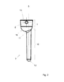
- Fig. 2 shows a detailed view of one of the reaction vessels 3 according to an embodiment.
- Each reaction vessel 3 of the set of reaction vessels 3 comprises an upper chamber 9 and a lower chamber 10, wherein the upper chamber 9 is of a wider diameter than the lower chamber 10, producing a shoulder area 18 between the upper and lower chamber 9, 10.
- the upper chamber 9 has an opening 15 for accepting fluid reactants and/or sample.
- the lower chamber 10 is typically an elongate tube, somewhat longer in proportion to its width, and aligned along a longitudinal axis B that is sensibly parallel with axis A when the support 2 is not rotated.
- the lower chamber 10 has a closed end 12, opposite to an open end 11, in communication with the upper chamber 9 and permitting the fluids to flow from the upper chamber 9 to the lower chamber 10 when a force such as centrifugal force is applied.
- the lower chamber 10 has essentially a cylindrical section, but other shapes are also possible.
- the lower chamber 10 can have a conical section or have a first portion with conical section and another portion with a cylindrical section.
- the lower chamber 10 may have an elliptical section with substantially parallel sides.
- the lower chamber 10 generally contains a matrix for separating agglutinates from non-agglutinates in the reaction mixture.
- a matrix may be comprised of any suitable material for separating agglutinates such as glass beads, polymer beads, filter paper, gel filtration media, sintered glass, plastics, such as described in patent EP0305337 .
- the wider upper chamber diameter facilitates the adding of the reagents and sample.
- the diameter of the lower chamber 10 is narrow enough such that when reagents and sample are added to the upper chamber 9, typically using a pipette assembly (not shown), the fluids remain in the upper chamber 9, and do not enter into the lower chamber 10, preventing their passage through the matrix, unless an additional force (such as centrifugation) is applied to effect their movement. It is therefore possible to exert control over the timing of the agglutination assay.
- the upper chamber 9 is eccentric with the lower chamber 10.
- the reagents and sample can be pipetted in the shoulder area 18, also eccentric with the lower chamber 10, allowing the fluids to be retained in the upper chamber 9 for a certain period of time before they are introduced into the separation matrix of the lower chamber 10.
- This conformation reduces the risk of having fluids pipetted directly to the top of the separation matrix in the lower chamber 10 and not retained in the upper chamber 10 during the incubation phase.
- the rotating support 1 further comprises a cup-shaped receptacle 7 within the disk-shaped support 2 and concentric with the rotation axis A.
- the receptacle 7 extends below and above the plane of the rotating support 2, but could also be placed otherwise, such as completely below or above the plane of the rotating support 2.
- the receptacle 7 is destined to receive fluids preparations containing, for example, reactants, diluents and/or test sample such as red blood cells, plasma, etc.
- the receptacle 7 can also comprise cover 8 provided with an opening 20 in order to retain the reactants and sample within the receptacle 7 when the rotating support 1 is centrifuged.
- the rotating support 1 can comprise no receptacle 7.
- the rotating support 1 can comprise several small receptacles angularly distributed between the center of the support 1 and its periphery.
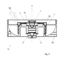
- Fig. 3 illustrates a cross section view of an analysis station 16 according to an embodiment, viewed through a line perpendicular to rotation axis A.
- the analysis station 16 comprises centrifugation device containing a drive shaft 17 adapted to drivingly hold the rotating support 1.
- the drive shaft 17 comprises a drive end 21 fixed coaxially on the drive shaft 17 and containing a recess 19 in which the receptacle 7 of the rotating support 1 can be fixedly fitted.
- the analysis station 16 can comprise a transport means (not represented) adapted to pick-up and fix the rotating support 1 on the drive shaft 17.
- the rotation axis A of the rotating support 1 is substantially coaxial with the rotation axis of the drive shaft 17.
- the analysis station 16 further comprises a cup-shaped housing 23 enclosing the drive shaft 17 and the rotating support 1.
- the external surface of the receptacle 7 in contact with the recess 19 comprises one or several ribs (not shown) cooperating with one or several corresponding grooves (also not shown) on the surface of the recess 19.
- the use of ribs and grooves allows avoiding possible unwanted radial displacements of the rotating support 1 in respect to the drive shaft 17, especially during rotation of the drive shaft 17 during centrifugation.
- the drive shaft 17 is rotated by a motor (not shown) controlled by a drive controller (also not represented) such as to rotate the rotating support 1 to a predetermined rotation speed.
- the rotating support 1 can be screwed to the drive shaft 17, directly or via the drive end 21.
- This latter holding arrangement can be advantageously used in the case the rotating support 1 does not comprises the receptacle 7.
- the analysis station 16 further comprises a stationary heating device, shown by the numeral 50 in Fig. 3 , adapted to heat the reactants and sample within subsets of the set of reaction vessels 3 at predetermined incubation temperatures, when the rotating support 1 is held on the drive shaft 17.
- a stationary heating device shown by the numeral 50 in Fig. 3 , adapted to heat the reactants and sample within subsets of the set of reaction vessels 3 at predetermined incubation temperatures, when the rotating support 1 is held on the drive shaft 17.
- the annular-shaped heating device 50 is disposed concentric with the rotation axis A, beneath the disk-shaped support 2.
- the outer diameter of the heating device 50 is small enough not to interfere with the surrounding set of reaction vessels 3, allowing the rotation vessels to pivot when the rotating support 1 is rotated.
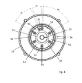
- Fig. 4 illustrates the analysis station 16 viewed from top. In the figure, rotating support 1 and the reaction vessels 3 are not shown.
- the heating device 50 comprises one first heating element 51 extending along an arc length intercepting an angle of about 20°, one second heating element 52 extending along an arc length intercepting an angle of about 40°, and five of a third heating element 53, each third heating element 53 extending along an arc length intercepting an angle of about 60°.
- the heating elements 51, 52, 53 are thermally separated from each other by an insulating separator 55 and are controlled separately in temperature.
- the insulating separator 55 can be made from any non-heat conducting materials such as plastics or ceramics. Alternatively, the insulating separator 55 can be an air gap.
- the stationary heating device 50 can selectively heat subsets comprising one or more reaction vessels 3.
- the rotating support 1 comprises twelve reaction vessels 3
- the latter can be held on the drive shaft 17 and be angularly positioned such that one of the reaction vessels 3 is aligned with the first heating element 51, another reaction vessel 3 is aligned with the second heating element 52, and the remaining reaction vessels 2 are aligned by pair of adjacent reaction vessels 2 with the five third heating elements 53.
- a subset comprising one or two reaction vessels 3 can be selectively heated by the first and/or second heating elements 51, 52, respectively.
- a subset comprising three and more reaction vessels 3 can be selectively heated by using, in combination, the first and/or second heating elements 51, 52 with one or more of the third heating elements 53.
- the first and second heating elements 51, 52 can be formed form a single element, for example by adding the insulating separator 55 to an element similar to one of the third heating elements 53, in a position such as to form two portions having an arc length corresponding to the ones of the first and second elements 51, 52, respectively.
- the predetermined incubation temperature can be different for the different subsets of reaction vessels 3. It is therefore possible to fill the different subsets of reaction vessels 3 with different type of reagents or samples that require different incubation temperatures. It is also possible to heat only some of the possible subsets for incubation, while keeping the other subsets at room temperature.
- the heating device 51, 52, 53 shown in Fig. 4 is also suitable for the rotating support 1 comprising a set with a number of reaction vessels 3 different than twelve.
- the rotating support 1 comprises a set of six reaction vessels 3
- the rotating support 1 can be positioned such that each of the six subsets comprising one reaction vessel 3 are aligned with each third heating element 53 and with the first or second heating element 51, 52, respectively.
- the rotating support 1 comprising a set of eighteen reaction vessels 3 can be positioned such that a subset of one reaction vessel 3 is aligned with the first heating element 51, a subset of two reaction vessels 3 is aligned with the second heating element 52, and each of the remaining five subsets of three reaction vessels 3 is aligned with one of the five third heating elements 53.
- the set of eighteen reaction vessels 3 can be advantageously used for performing numerous simultaneous tests.
- the heating device 50, 51, 52, 53 is disposed at an elevation corresponding to the upper chambers 9 of the set of reaction vessels 3 when the rotating support 1 is held on the drive shaft 17, as shown in Fig. 3 .
- the outer side of the heating device 50 can be shaped such as to be substantially conformal with the shape of the upper chamber 9.
- the distance between the outer surface of the heating device 50 and the upper chambers 9 is inferior to 1 mm. In this configuration, optimal heat transfer can be achieved between the heating elements 51, 52, 53 of the heating device 50 and the reaction vessels 3.
- a method for performing an agglutination reaction and separation assay by using the analysis station 16 disclosed herein comprises the steps of:
- the incubation is performed at a predetermined incubation temperature and period of time sufficient to allow for forming agglutinates.
- the incubation can be performed during 7 to 10 minutes at a temperature comprised between room temperature and 37°C, depending on the reactants and/or sample used, as described above.
- the size and amount of agglutinates are a quantitative indicator of the level or concentration in the sample, or an indicator of the reaction strength. The absence of agglutinate indicates that no reaction has occurred.
- the heating elements 51, 52, 53 are controlled separately in temperature by a temperature controller (not shown) adapted to selectively set a possibly different predetermined temperature level on each of the heating elements 51, 52, 53.
- the predetermined temperature levels can be selected such as to achieve heating of the reactants and/or sample within the upper chambers 9 at the desired predetermined incubation temperatures.
- the temperature controller can also be adapted to hold the predetermined temperature level for varying lengths of time or altering them at different rates of change.
- the analysis station 16 further comprises a control unit (not represented) connected to the temperature controller in order to automatically control the predetermined temperature levels on the different heating elements 51, 52, 53.
- the analysis station 16 can further comprise a temperature sensor device (not shown) for measuring the temperature of the heating elements 51, 52, 53 or of the reaction vessels 3, preferably of the upper chambers 9.
- the temperature sensor device can be a contactless temperature sensor such as an infrared radiation thermometer.
- the temperature sensor device can be adapted to provide a signal to the temperature controller in order, for example, to adjust the predetermined temperature levels if needed.
- the set of reaction vessels 3 Prior to incubating, the set of reaction vessels 3 can be angularly positioned with respect to the heating elements 51, 52, 53 allowing for selectively heat subsets comprising one or more reaction vessels 3 at predetermined incubation temperatures.
- the subset comprising one reaction vessel 3 can be selectively heated by the first heating element 51
- the subset comprising two reaction vessels 3 can be selectively heated by the second heating element 52
- the five subsets comprising three reaction vessels 3 can be selectively heated by the third heating elements 53.
- the heating elements 51, 52, 53 being controlled independently in temperature, the predetermined incubation temperature can be different for the different subsets. It is then possible to draw different reagents and samples requiring different incubation temperatures in the reaction vessels 3 of the different subsets. It is also possible to use only some subsets for performing the assay tests where only these subsets are incubated.
- Positioning of the set of reaction vessels 3 can be performed manually.
- the rotating support 1 can comprise at least one positional reference (not shown).
- the positional reference can be aligned with one or more corresponding reference marks (also not shown), for example located on the housing 23.
- the positional reference can be a protruding or recessed structure possibly engaging with a corresponding counter-structure (see numeral 22 in Fig. 4 ), for example, provided on the drive end 21.
- the analysis station 16 further comprises a control unit (not represented) connected to the drive controller to operate the drive shaft 17 such as to position the rotating support 1 automatically.
- the analysis station 16 can further comprises a position sensor (not represented) adapted for measuring the angular position of the rotating support 1 in order to ensure accurate positioning of the set of reaction vessels 3 with respect to the respective heating elements 51, 52, 53.
- the reagents and samples Prior to pipetting reagents and samples into the upper chamber 9, the reagents and samples can be pipetted and mixed together into the receptacle 7, for example, through the cover opening 20. The mixed reagents and samples are then pipetted in the shoulder area 18 the reaction vessels 3.
- control unit is connected to the pipette assembly and to the transport means.
- the control unit operates the pipette assembly to automatically draw the reagents and sample into the receptacle 7 and into the upper chamber 9.
- control unit operates the transport assembly to carry the rotating support 1 on the drive shaft 17 in an automated fashion.
- the different reagents and samples can be pipetted in different subsets of reaction vessels 3 according to their position relative to the heating elements 51, 52, 53, thus to their predetermined incubation temperatures.
- the centrifuging speed and time, controlled by the drive controller, should be suitable to allow the agglutinates, if any, to form a cluster or band in the matrix column. Unagglutinated materials migrate down through the separation matrix while agglutinates remain on top of the separation matrix, or are distributed at various distances from the top of the matrix, depending on the degree of agglutination.
- the centrifuging speed and time can be controlled by the control unit in the case the latter is connected to the drive controller.
- the analysis system 16 further comprises reading and interpretation means, schematically represented by the numeral 56 in Fig. 4 , designed to optically or otherwise detect cluster agglutinate and/or band or button formation within a certain area of the agglutination reaction zone in the lower chamber 10. Alternatively, observation can be performed manually.
- a computer program product configured to be operable on the control unit or any other external processing unit (not represented) controlling the control unit, and adapted to control at least one of the pipette assembly, the transport means, the drive controller and the temperature controller.
- the computer program product is configured to carry out at least one of the steps of carry the rotating support 1 on the drive shaft 17, operate the pipette assembly, position the rotating support 1, control the predetermined incubation temperature and incubation time for the heating elements 51, 52, 53, and/or control the centrifuging speed and time of the rotating support 1, when the program is executed by the control unit or the any other external processing unit.
- the rotating support 1 can further comprise an identification means (not represented) such as a bar code or a read/write RFID tag attached thereto which contains coded information relating to the reactants and sample contained within the reaction vessels 3, such as the reactant types and their concentration, and to the tests to be performed.
- the analysis station 16 can also include a reader adapted to read the information contained in the identification means.
- the identification means can further comprises information for operating the temperature controller, or control unit, in order to set adequate heating temperatures to the heating elements 51, 52, 53 in accordance with the position of the set of reaction vessels 3.
- the information can further be used for operating the drive controller, or control unit, in order to position the reaction vessels 3 with respect to the heating elements 51, 52, 53.
- the information comprised in the identification means can be inputted in the computer program product in order to controlling the control unit, or the any other external processing unit, accordingly.
- the heating device 50 comprises more or less than five of the third heating element 53.
- the heating device 50 comprises seven of the third heating element 53.
- Such heating device 50 is adapted, for example, for using the rotating support 1 having a set comprising up to twenty four reaction vessels 3.
- the heating device 50 can comprise one first heating element 51 and a plurality of the second heating element 52, or only a plurality of first heating elements 51. The latter configuration allows for selectively heat a set of reaction vessels 3 in any possible combinations of subsets of one reaction vessel 3.
- the heating device 50 may not necessarily be annular-shaped with arc-shaped heating elements 51, 52, 53.
- the heating device 50 comprises several spatially separated heating elements arranged, for example, in a hexagonal pattern within the inner diameter bounded by the set of reaction vessels 3.
- the heating elements can be rectangular, hexagonal or cylindrical shaped and are controlled separately in temperature by the temperature controller. What is important here, is that the different heating element be able to heat one or more subsets of reaction vessels 3 depending on the alignment of each subset with the different heating elements.
- the heating elements can extend along the whole length of the reaction vessels 3 in order to be able to heat the upper and lower chambers 9, 10 substantially uniformly.
- the heating device 50 has the form of an annular stripe concentric with the rotation axis A, and is placed on top of the rotating support 1, for example, on top of the upper chambers 9 of the reaction vessels 3.
- the different heating elements 51, 52, 53 can be formed, for example, by sectioning the annular stripe in segments having the appropriate arc length and arranged such that the upper chambers 9 are accessible for pipetting during the pipetting steps and are located above the upper chambers 9 during the incubating step.
- Such a configuration can be achieved, for example, by providing at least an empty section in the annular stripe and changing the angular position of the rotating support 1 between the pipetting and the incubating steps.
Landscapes
- Health & Medical Sciences (AREA)
- Clinical Laboratory Science (AREA)
- Chemical & Material Sciences (AREA)
- Chemical Kinetics & Catalysis (AREA)
- Automatic Analysis And Handling Materials Therefor (AREA)
Priority Applications (3)
| Application Number | Priority Date | Filing Date | Title |
|---|---|---|---|
| EP10158303.7A EP2372366B1 (fr) | 2010-03-30 | 2010-03-30 | Station d'analyse dotée d'un système d'incubation |
| ES10158303T ES2748332T3 (es) | 2010-03-30 | 2010-03-30 | Estación de análisis con sistema de incubación |
| PT101583037T PT2372366T (pt) | 2010-03-30 | 2010-03-30 | Estação de análise com sistema de incubação. |
Applications Claiming Priority (1)
| Application Number | Priority Date | Filing Date | Title |
|---|---|---|---|
| EP10158303.7A EP2372366B1 (fr) | 2010-03-30 | 2010-03-30 | Station d'analyse dotée d'un système d'incubation |
Publications (2)
| Publication Number | Publication Date |
|---|---|
| EP2372366A1 true EP2372366A1 (fr) | 2011-10-05 |
| EP2372366B1 EP2372366B1 (fr) | 2019-07-03 |
Family
ID=42657570
Family Applications (1)
| Application Number | Title | Priority Date | Filing Date |
|---|---|---|---|
| EP10158303.7A Active EP2372366B1 (fr) | 2010-03-30 | 2010-03-30 | Station d'analyse dotée d'un système d'incubation |
Country Status (3)
| Country | Link |
|---|---|
| EP (1) | EP2372366B1 (fr) |
| ES (1) | ES2748332T3 (fr) |
| PT (1) | PT2372366T (fr) |
Cited By (5)
| Publication number | Priority date | Publication date | Assignee | Title |
|---|---|---|---|---|
| CN108627655A (zh) * | 2017-03-25 | 2018-10-09 | 长沙英泰仪器有限公司 | 离心孵育仪 |
| CN113219186A (zh) * | 2021-01-29 | 2021-08-06 | 武汉市农业科学院 | 一种全自动重金属分析仪 |
| EP3888795A1 (fr) * | 2020-03-30 | 2021-10-06 | Sysmex Corporation | Centrifugeuse et dispositif de préparation d'échantillon |
| CN115184404A (zh) * | 2022-09-08 | 2022-10-14 | 合肥司南金属材料有限公司 | 一种钼铜合金导热性能测试装置 |
| WO2022232781A1 (fr) * | 2021-04-30 | 2022-11-03 | Laboratory Corporation Of America Holdings | Ensemble tube à centrifuger, rotor à centrifuger et centrifugeuse |
Citations (8)
| Publication number | Priority date | Publication date | Assignee | Title |
|---|---|---|---|---|
| GB1018285A (en) * | 1963-10-17 | 1966-01-26 | Mse Holdings Ltd | Improvements in or relating to the temperature control of centrifuges |
| US4066407A (en) * | 1976-12-16 | 1978-01-03 | Vincent Lupica | Body fluid testing system and process |
| US4244694A (en) * | 1978-03-31 | 1981-01-13 | Union Carbide Corporation | Reactor/separator device for use in automated solid phase immunoassay |
| EP0305337A1 (fr) | 1987-08-24 | 1989-03-01 | Stiftung Für Diagnostische Forschung | Procédé de détection des antigènes et/ou des anticorps et nécéssaire pour sa mise en oeuvre |
| US5869347A (en) * | 1996-03-18 | 1999-02-09 | Stiftung Fur Diagnostische Forschung Praz-Rond | Particle immunoassay using a compact matrix |
| WO2001004600A1 (fr) * | 1999-07-09 | 2001-01-18 | Genevac Ltd. | Evaporateur centrifuge pour echantillons a ecran de protection contre la chaleur directe et chauffage uniforme |
| US20030231878A1 (en) * | 2002-05-22 | 2003-12-18 | John Shigeura | Non-contact radiant heating and temperature sensing device for a chemical reaction chamber |
| EP1450159A2 (fr) * | 2003-02-24 | 2004-08-25 | Ortho-Clinical Diagnostics, Inc. | Procédé et appareil de détection de l'agglutinement des analyses |
-
2010
- 2010-03-30 EP EP10158303.7A patent/EP2372366B1/fr active Active
- 2010-03-30 PT PT101583037T patent/PT2372366T/pt unknown
- 2010-03-30 ES ES10158303T patent/ES2748332T3/es active Active
Patent Citations (8)
| Publication number | Priority date | Publication date | Assignee | Title |
|---|---|---|---|---|
| GB1018285A (en) * | 1963-10-17 | 1966-01-26 | Mse Holdings Ltd | Improvements in or relating to the temperature control of centrifuges |
| US4066407A (en) * | 1976-12-16 | 1978-01-03 | Vincent Lupica | Body fluid testing system and process |
| US4244694A (en) * | 1978-03-31 | 1981-01-13 | Union Carbide Corporation | Reactor/separator device for use in automated solid phase immunoassay |
| EP0305337A1 (fr) | 1987-08-24 | 1989-03-01 | Stiftung Für Diagnostische Forschung | Procédé de détection des antigènes et/ou des anticorps et nécéssaire pour sa mise en oeuvre |
| US5869347A (en) * | 1996-03-18 | 1999-02-09 | Stiftung Fur Diagnostische Forschung Praz-Rond | Particle immunoassay using a compact matrix |
| WO2001004600A1 (fr) * | 1999-07-09 | 2001-01-18 | Genevac Ltd. | Evaporateur centrifuge pour echantillons a ecran de protection contre la chaleur directe et chauffage uniforme |
| US20030231878A1 (en) * | 2002-05-22 | 2003-12-18 | John Shigeura | Non-contact radiant heating and temperature sensing device for a chemical reaction chamber |
| EP1450159A2 (fr) * | 2003-02-24 | 2004-08-25 | Ortho-Clinical Diagnostics, Inc. | Procédé et appareil de détection de l'agglutinement des analyses |
Cited By (7)
| Publication number | Priority date | Publication date | Assignee | Title |
|---|---|---|---|---|
| CN108627655A (zh) * | 2017-03-25 | 2018-10-09 | 长沙英泰仪器有限公司 | 离心孵育仪 |
| EP3888795A1 (fr) * | 2020-03-30 | 2021-10-06 | Sysmex Corporation | Centrifugeuse et dispositif de préparation d'échantillon |
| JP2021162321A (ja) * | 2020-03-30 | 2021-10-11 | シスメックス株式会社 | 遠心分離機および試料調製装置 |
| CN113219186A (zh) * | 2021-01-29 | 2021-08-06 | 武汉市农业科学院 | 一种全自动重金属分析仪 |
| CN113219186B (zh) * | 2021-01-29 | 2024-02-09 | 武汉市农业科学院 | 一种全自动重金属分析仪 |
| WO2022232781A1 (fr) * | 2021-04-30 | 2022-11-03 | Laboratory Corporation Of America Holdings | Ensemble tube à centrifuger, rotor à centrifuger et centrifugeuse |
| CN115184404A (zh) * | 2022-09-08 | 2022-10-14 | 合肥司南金属材料有限公司 | 一种钼铜合金导热性能测试装置 |
Also Published As
| Publication number | Publication date |
|---|---|
| PT2372366T (pt) | 2019-10-24 |
| EP2372366B1 (fr) | 2019-07-03 |
| ES2748332T3 (es) | 2020-03-16 |
Similar Documents
| Publication | Publication Date | Title |
|---|---|---|
| EP2367632B1 (fr) | Dispositif, système d'analyse et procédé pour réaliser des dosages d'agglutination | |
| JP7233403B2 (ja) | 前処理カルーセルを有する診断分析装置および関連方法 | |
| EP2459314B1 (fr) | Plaque d'échantillon | |
| US7666355B2 (en) | Automated analyzer | |
| EP1450159A2 (fr) | Procédé et appareil de détection de l'agglutinement des analyses | |
| CA2172363C (fr) | Chasse de bulle d'une seringue et procede | |
| EP2124054B1 (fr) | Appareil de tests d'immunodiagnostic ayant au moins un imageur pour fournir des évaluations d'agglutination préalables pendant le cycle de centrifugation | |
| JP2009530606A (ja) | 増強型磁気粒子ステアリング | |
| CA2069531A1 (fr) | Caroussel porte-specimens pour dosages | |
| CA2719430C (fr) | Element de test d'immunodiagnostic ayant une couche de faiblesse en feuille | |
| CA2069545A1 (fr) | Bouteille avec bouchon renfermant un reactif | |
| CA2069530A1 (fr) | Trousse de reactifs pour dosages immunologiques | |
| EP2372366B1 (fr) | Station d'analyse dotée d'un système d'incubation | |
| CN103869089B (zh) | 将多类诊断测试消耗品保持在随机访问单个容器中的方法 | |
| EP2746775B1 (fr) | Dispositif et procédé de transfert de récipients de réaction | |
| EP2662693A1 (fr) | Centrifugation à passe fractionnée d'éléments de test | |
| CN110470852A (zh) | 用于分离试验样品中包含的干扰物质的实验室系统和方法 | |
| US5318748A (en) | Centrifuge vessel for automated solid-phase immunoassay having integral coaxial waste chamber | |
| US6582912B1 (en) | Device, method and apparatus for implementing the method, for dosing at least a particular constituent in a product sample | |
| Boyd et al. | Automation in the clinical laboratory | |
| AU2428092A (en) | Reagent handling system for automated clinical analyzer apparatus | |
| US20060154372A1 (en) | Providing additional motion in assays |
Legal Events
| Date | Code | Title | Description |
|---|---|---|---|
| PUAI | Public reference made under article 153(3) epc to a published international application that has entered the european phase |
Free format text: ORIGINAL CODE: 0009012 |
|
| AK | Designated contracting states |
Kind code of ref document: A1 Designated state(s): AT BE BG CH CY CZ DE DK EE ES FI FR GB GR HR HU IE IS IT LI LT LU LV MC MK MT NL NO PL PT RO SE SI SK SM TR |
|
| AX | Request for extension of the european patent |
Extension state: AL BA ME RS |
|
| 17P | Request for examination filed |
Effective date: 20120326 |
|
| STAA | Information on the status of an ep patent application or granted ep patent |
Free format text: STATUS: EXAMINATION IS IN PROGRESS |
|
| 17Q | First examination report despatched |
Effective date: 20171011 |
|
| GRAP | Despatch of communication of intention to grant a patent |
Free format text: ORIGINAL CODE: EPIDOSNIGR1 |
|
| STAA | Information on the status of an ep patent application or granted ep patent |
Free format text: STATUS: GRANT OF PATENT IS INTENDED |
|
| INTG | Intention to grant announced |
Effective date: 20180717 |
|
| GRAJ | Information related to disapproval of communication of intention to grant by the applicant or resumption of examination proceedings by the epo deleted |
Free format text: ORIGINAL CODE: EPIDOSDIGR1 |
|
| STAA | Information on the status of an ep patent application or granted ep patent |
Free format text: STATUS: EXAMINATION IS IN PROGRESS |
|
| GRAS | Grant fee paid |
Free format text: ORIGINAL CODE: EPIDOSNIGR3 |
|
| STAA | Information on the status of an ep patent application or granted ep patent |
Free format text: STATUS: GRANT OF PATENT IS INTENDED |
|
| GRAP | Despatch of communication of intention to grant a patent |
Free format text: ORIGINAL CODE: EPIDOSNIGR1 |
|
| INTC | Intention to grant announced (deleted) | ||
| INTG | Intention to grant announced |
Effective date: 20181220 |
|
| GRAA | (expected) grant |
Free format text: ORIGINAL CODE: 0009210 |
|
| STAA | Information on the status of an ep patent application or granted ep patent |
Free format text: STATUS: THE PATENT HAS BEEN GRANTED |
|
| AK | Designated contracting states |
Kind code of ref document: B1 Designated state(s): AT BE BG CH CY CZ DE DK EE ES FI FR GB GR HR HU IE IS IT LI LT LU LV MC MK MT NL NO PL PT RO SE SI SK SM TR |
|
| REG | Reference to a national code |
Ref country code: GB Ref legal event code: FG4D |
|
| REG | Reference to a national code |
Ref country code: CH Ref legal event code: EP Ref country code: AT Ref legal event code: REF Ref document number: 1151634 Country of ref document: AT Kind code of ref document: T Effective date: 20190715 |
|
| REG | Reference to a national code |
Ref country code: IE Ref legal event code: FG4D |
|
| REG | Reference to a national code |
Ref country code: DE Ref legal event code: R096 Ref document number: 602010059786 Country of ref document: DE |
|
| REG | Reference to a national code |
Ref country code: CH Ref legal event code: NV Representative=s name: P&TS SA, CH |
|
| REG | Reference to a national code |
Ref country code: SE Ref legal event code: TRGR |
|
| REG | Reference to a national code |
Ref country code: PT Ref legal event code: SC4A Ref document number: 2372366 Country of ref document: PT Date of ref document: 20191024 Kind code of ref document: T Free format text: AVAILABILITY OF NATIONAL TRANSLATION Effective date: 20191003 |
|
| REG | Reference to a national code |
Ref country code: NL Ref legal event code: MP Effective date: 20190703 |
|
| REG | Reference to a national code |
Ref country code: NO Ref legal event code: T2 Effective date: 20190703 |
|
| REG | Reference to a national code |
Ref country code: LT Ref legal event code: MG4D |
|
| PG25 | Lapsed in a contracting state [announced via postgrant information from national office to epo] |
Ref country code: LT Free format text: LAPSE BECAUSE OF FAILURE TO SUBMIT A TRANSLATION OF THE DESCRIPTION OR TO PAY THE FEE WITHIN THE PRESCRIBED TIME-LIMIT Effective date: 20190703 Ref country code: HR Free format text: LAPSE BECAUSE OF FAILURE TO SUBMIT A TRANSLATION OF THE DESCRIPTION OR TO PAY THE FEE WITHIN THE PRESCRIBED TIME-LIMIT Effective date: 20190703 Ref country code: BG Free format text: LAPSE BECAUSE OF FAILURE TO SUBMIT A TRANSLATION OF THE DESCRIPTION OR TO PAY THE FEE WITHIN THE PRESCRIBED TIME-LIMIT Effective date: 20191003 Ref country code: NL Free format text: LAPSE BECAUSE OF FAILURE TO SUBMIT A TRANSLATION OF THE DESCRIPTION OR TO PAY THE FEE WITHIN THE PRESCRIBED TIME-LIMIT Effective date: 20190703 Ref country code: CZ Free format text: LAPSE BECAUSE OF FAILURE TO SUBMIT A TRANSLATION OF THE DESCRIPTION OR TO PAY THE FEE WITHIN THE PRESCRIBED TIME-LIMIT Effective date: 20190703 |
|
| PG25 | Lapsed in a contracting state [announced via postgrant information from national office to epo] |
Ref country code: IS Free format text: LAPSE BECAUSE OF FAILURE TO SUBMIT A TRANSLATION OF THE DESCRIPTION OR TO PAY THE FEE WITHIN THE PRESCRIBED TIME-LIMIT Effective date: 20191103 Ref country code: GR Free format text: LAPSE BECAUSE OF FAILURE TO SUBMIT A TRANSLATION OF THE DESCRIPTION OR TO PAY THE FEE WITHIN THE PRESCRIBED TIME-LIMIT Effective date: 20191004 Ref country code: LV Free format text: LAPSE BECAUSE OF FAILURE TO SUBMIT A TRANSLATION OF THE DESCRIPTION OR TO PAY THE FEE WITHIN THE PRESCRIBED TIME-LIMIT Effective date: 20190703 |
|
| REG | Reference to a national code |
Ref country code: DE Ref legal event code: R082 Ref document number: 602010059786 Country of ref document: DE Representative=s name: BECK & ROESSIG EUROPEAN PATENT ATTORNEYS, DE Ref country code: DE Ref legal event code: R082 Ref document number: 602010059786 Country of ref document: DE Representative=s name: BECK & ROESSIG - EUROPEAN PATENT ATTORNEYS, DE |
|
| REG | Reference to a national code |
Ref country code: ES Ref legal event code: FG2A Ref document number: 2748332 Country of ref document: ES Kind code of ref document: T3 Effective date: 20200316 |
|
| PG25 | Lapsed in a contracting state [announced via postgrant information from national office to epo] |
Ref country code: TR Free format text: LAPSE BECAUSE OF FAILURE TO SUBMIT A TRANSLATION OF THE DESCRIPTION OR TO PAY THE FEE WITHIN THE PRESCRIBED TIME-LIMIT Effective date: 20190703 |
|
| PG25 | Lapsed in a contracting state [announced via postgrant information from national office to epo] |
Ref country code: DK Free format text: LAPSE BECAUSE OF FAILURE TO SUBMIT A TRANSLATION OF THE DESCRIPTION OR TO PAY THE FEE WITHIN THE PRESCRIBED TIME-LIMIT Effective date: 20190703 Ref country code: EE Free format text: LAPSE BECAUSE OF FAILURE TO SUBMIT A TRANSLATION OF THE DESCRIPTION OR TO PAY THE FEE WITHIN THE PRESCRIBED TIME-LIMIT Effective date: 20190703 Ref country code: RO Free format text: LAPSE BECAUSE OF FAILURE TO SUBMIT A TRANSLATION OF THE DESCRIPTION OR TO PAY THE FEE WITHIN THE PRESCRIBED TIME-LIMIT Effective date: 20190703 Ref country code: PL Free format text: LAPSE BECAUSE OF FAILURE TO SUBMIT A TRANSLATION OF THE DESCRIPTION OR TO PAY THE FEE WITHIN THE PRESCRIBED TIME-LIMIT Effective date: 20190703 |
|
| PG25 | Lapsed in a contracting state [announced via postgrant information from national office to epo] |
Ref country code: SM Free format text: LAPSE BECAUSE OF FAILURE TO SUBMIT A TRANSLATION OF THE DESCRIPTION OR TO PAY THE FEE WITHIN THE PRESCRIBED TIME-LIMIT Effective date: 20190703 Ref country code: SK Free format text: LAPSE BECAUSE OF FAILURE TO SUBMIT A TRANSLATION OF THE DESCRIPTION OR TO PAY THE FEE WITHIN THE PRESCRIBED TIME-LIMIT Effective date: 20190703 Ref country code: IS Free format text: LAPSE BECAUSE OF FAILURE TO SUBMIT A TRANSLATION OF THE DESCRIPTION OR TO PAY THE FEE WITHIN THE PRESCRIBED TIME-LIMIT Effective date: 20200224 |
|
| REG | Reference to a national code |
Ref country code: DE Ref legal event code: R097 Ref document number: 602010059786 Country of ref document: DE |
|
| PLBE | No opposition filed within time limit |
Free format text: ORIGINAL CODE: 0009261 |
|
| STAA | Information on the status of an ep patent application or granted ep patent |
Free format text: STATUS: NO OPPOSITION FILED WITHIN TIME LIMIT |
|
| PG2D | Information on lapse in contracting state deleted |
Ref country code: IS |
|
| 26N | No opposition filed |
Effective date: 20200603 |
|
| PG25 | Lapsed in a contracting state [announced via postgrant information from national office to epo] |
Ref country code: SI Free format text: LAPSE BECAUSE OF FAILURE TO SUBMIT A TRANSLATION OF THE DESCRIPTION OR TO PAY THE FEE WITHIN THE PRESCRIBED TIME-LIMIT Effective date: 20190703 |
|
| PG25 | Lapsed in a contracting state [announced via postgrant information from national office to epo] |
Ref country code: IE Free format text: LAPSE BECAUSE OF NON-PAYMENT OF DUE FEES Effective date: 20200330 |
|
| REG | Reference to a national code |
Ref country code: DE Ref legal event code: R081 Ref document number: 602010059786 Country of ref document: DE Owner name: HAEMOKINESIS LTD., HALLAM, AU Free format text: FORMER OWNER: SYMBION MEDICAL SYSTEMS SARL, AVENCHES, CH Ref country code: DE Ref legal event code: R082 Ref document number: 602010059786 Country of ref document: DE Representative=s name: BECK & ROESSIG - EUROPEAN PATENT ATTORNEYS, DE Ref country code: DE Ref legal event code: R081 Ref document number: 602010059786 Country of ref document: DE Owner name: HAEMOKINESIS PTY LTD, HALLAM, AU Free format text: FORMER OWNER: SYMBION MEDICAL SYSTEMS SARL, AVENCHES, CH |
|
| REG | Reference to a national code |
Ref country code: FI Ref legal event code: PCE Owner name: HAEMOKINESIS PTY LTD |
|
| REG | Reference to a national code |
Ref country code: CH Ref legal event code: PUE Owner name: HAEMOKINESIS PTY LTD, AU Free format text: FORMER OWNER: SYMBION MEDICAL SYSTEMS SARL, CH |
|
| REG | Reference to a national code |
Ref country code: ES Ref legal event code: PC2A Owner name: HAEMOKINESIS PTY LTD Effective date: 20210413 |
|
| REG | Reference to a national code |
Ref country code: LU Ref legal event code: PD Owner name: HAEMOKINESIS PTY LTD; AU Free format text: FORMER OWNER: SYMBION MEDICAL SYSTEMS SARL Effective date: 20210428 |
|
| REG | Reference to a national code |
Ref country code: BE Ref legal event code: PD Owner name: HAEMOKINESIS PTY LTD; AU Free format text: DETAILS ASSIGNMENT: CHANGE OF OWNER(S), ASSIGNMENT; FORMER OWNER NAME: SYMBION MEDICAL SYSTEMS SARL Effective date: 20210428 |
|
| REG | Reference to a national code |
Ref country code: NO Ref legal event code: CHAD Owner name: HAEMOKINESIS PTY LTD, AU |
|
| REG | Reference to a national code |
Ref country code: GB Ref legal event code: 732E Free format text: REGISTERED BETWEEN 20210715 AND 20210721 |
|
| REG | Reference to a national code |
Ref country code: AT Ref legal event code: PC Ref document number: 1151634 Country of ref document: AT Kind code of ref document: T Owner name: HAEMOKINESIS PTY LTD, AU Effective date: 20210618 |
|
| REG | Reference to a national code |
Ref country code: DE Ref legal event code: R081 Ref document number: 602010059786 Country of ref document: DE Owner name: HAEMOKINESIS LTD., HALLAM, AU Free format text: FORMER OWNER: HAEMOKINESIS PTY LTD, HALLAM, VICTORIA, AU Ref country code: NO Ref legal event code: CHAD Owner name: HAEMOKINESIS LIMITED, AU |
|
| REG | Reference to a national code |
Ref country code: FI Ref legal event code: PCE Owner name: HAEMOKINESIS LIMITED |
|
| REG | Reference to a national code |
Ref country code: LU Ref legal event code: HC Owner name: HAEMOKINESIS LIMITED; AU Free format text: FORMER OWNER: HAEMOKINESIS PTY LTD Effective date: 20220225 |
|
| REG | Reference to a national code |
Ref country code: ES Ref legal event code: PC2A Owner name: HAEMOKINESIS LIMITED Effective date: 20220517 |
|
| PG25 | Lapsed in a contracting state [announced via postgrant information from national office to epo] |
Ref country code: MT Free format text: LAPSE BECAUSE OF FAILURE TO SUBMIT A TRANSLATION OF THE DESCRIPTION OR TO PAY THE FEE WITHIN THE PRESCRIBED TIME-LIMIT Effective date: 20190703 Ref country code: CY Free format text: LAPSE BECAUSE OF FAILURE TO SUBMIT A TRANSLATION OF THE DESCRIPTION OR TO PAY THE FEE WITHIN THE PRESCRIBED TIME-LIMIT Effective date: 20190703 |
|
| PG25 | Lapsed in a contracting state [announced via postgrant information from national office to epo] |
Ref country code: MK Free format text: LAPSE BECAUSE OF FAILURE TO SUBMIT A TRANSLATION OF THE DESCRIPTION OR TO PAY THE FEE WITHIN THE PRESCRIBED TIME-LIMIT Effective date: 20190703 |
|
| REG | Reference to a national code |
Ref country code: AT Ref legal event code: UEP Ref document number: 1151634 Country of ref document: AT Kind code of ref document: T Effective date: 20190703 |
|
| PGFP | Annual fee paid to national office [announced via postgrant information from national office to epo] |
Ref country code: NO Payment date: 20230329 Year of fee payment: 14 Ref country code: MC Payment date: 20230324 Year of fee payment: 14 Ref country code: LU Payment date: 20230330 Year of fee payment: 14 Ref country code: FR Payment date: 20230330 Year of fee payment: 14 Ref country code: FI Payment date: 20230328 Year of fee payment: 14 Ref country code: AT Payment date: 20230327 Year of fee payment: 14 |
|
| PGFP | Annual fee paid to national office [announced via postgrant information from national office to epo] |
Ref country code: SE Payment date: 20230327 Year of fee payment: 14 Ref country code: PT Payment date: 20230323 Year of fee payment: 14 Ref country code: IT Payment date: 20230327 Year of fee payment: 14 Ref country code: GB Payment date: 20230330 Year of fee payment: 14 Ref country code: BE Payment date: 20230327 Year of fee payment: 14 |
|
| PGFP | Annual fee paid to national office [announced via postgrant information from national office to epo] |
Ref country code: ES Payment date: 20230529 Year of fee payment: 14 Ref country code: DE Payment date: 20230330 Year of fee payment: 14 Ref country code: CH Payment date: 20230428 Year of fee payment: 14 |
|
| REG | Reference to a national code |
Ref country code: DE Ref legal event code: R119 Ref document number: 602010059786 Country of ref document: DE |
|
| PG25 | Lapsed in a contracting state [announced via postgrant information from national office to epo] |
Ref country code: FI Free format text: LAPSE BECAUSE OF NON-PAYMENT OF DUE FEES Effective date: 20240330 |
|
| REG | Reference to a national code |
Ref country code: SE Ref legal event code: EUG |
|
| PG25 | Lapsed in a contracting state [announced via postgrant information from national office to epo] |
Ref country code: FI Free format text: LAPSE BECAUSE OF NON-PAYMENT OF DUE FEES Effective date: 20240330 |
|
| REG | Reference to a national code |
Ref country code: CH Ref legal event code: PL |
|
| REG | Reference to a national code |
Ref country code: AT Ref legal event code: MM01 Ref document number: 1151634 Country of ref document: AT Kind code of ref document: T Effective date: 20240330 |
|
| PG25 | Lapsed in a contracting state [announced via postgrant information from national office to epo] |
Ref country code: LU Free format text: LAPSE BECAUSE OF NON-PAYMENT OF DUE FEES Effective date: 20240330 |
|
| PG25 | Lapsed in a contracting state [announced via postgrant information from national office to epo] |
Ref country code: MC Free format text: LAPSE BECAUSE OF NON-PAYMENT OF DUE FEES Effective date: 20240402 |
|
| GBPC | Gb: european patent ceased through non-payment of renewal fee |
Effective date: 20240330 |
|
| PG25 | Lapsed in a contracting state [announced via postgrant information from national office to epo] |
Ref country code: MC Free format text: LAPSE BECAUSE OF NON-PAYMENT OF DUE FEES Effective date: 20240402 Ref country code: LU Free format text: LAPSE BECAUSE OF NON-PAYMENT OF DUE FEES Effective date: 20240330 |
|
| REG | Reference to a national code |
Ref country code: BE Ref legal event code: MM Effective date: 20240331 |
|
| PG25 | Lapsed in a contracting state [announced via postgrant information from national office to epo] |
Ref country code: DE Free format text: LAPSE BECAUSE OF NON-PAYMENT OF DUE FEES Effective date: 20241001 |
|
| PG25 | Lapsed in a contracting state [announced via postgrant information from national office to epo] |
Ref country code: NO Free format text: LAPSE BECAUSE OF NON-PAYMENT OF DUE FEES Effective date: 20240331 |
|
| PG25 | Lapsed in a contracting state [announced via postgrant information from national office to epo] |
Ref country code: BE Free format text: LAPSE BECAUSE OF NON-PAYMENT OF DUE FEES Effective date: 20240331 |
|
| PG25 | Lapsed in a contracting state [announced via postgrant information from national office to epo] |
Ref country code: GB Free format text: LAPSE BECAUSE OF NON-PAYMENT OF DUE FEES Effective date: 20240330 |
|
| PG25 | Lapsed in a contracting state [announced via postgrant information from national office to epo] |
Ref country code: FR Free format text: LAPSE BECAUSE OF NON-PAYMENT OF DUE FEES Effective date: 20240331 |
|
| PG25 | Lapsed in a contracting state [announced via postgrant information from national office to epo] |
Ref country code: AT Free format text: LAPSE BECAUSE OF NON-PAYMENT OF DUE FEES Effective date: 20240330 |
|
| PG25 | Lapsed in a contracting state [announced via postgrant information from national office to epo] |
Ref country code: NO Free format text: LAPSE BECAUSE OF NON-PAYMENT OF DUE FEES Effective date: 20240331 Ref country code: GB Free format text: LAPSE BECAUSE OF NON-PAYMENT OF DUE FEES Effective date: 20240330 Ref country code: FR Free format text: LAPSE BECAUSE OF NON-PAYMENT OF DUE FEES Effective date: 20240331 Ref country code: DE Free format text: LAPSE BECAUSE OF NON-PAYMENT OF DUE FEES Effective date: 20241001 Ref country code: BE Free format text: LAPSE BECAUSE OF NON-PAYMENT OF DUE FEES Effective date: 20240331 Ref country code: AT Free format text: LAPSE BECAUSE OF NON-PAYMENT OF DUE FEES Effective date: 20240330 Ref country code: CH Free format text: LAPSE BECAUSE OF NON-PAYMENT OF DUE FEES Effective date: 20240331 |
|
| PG25 | Lapsed in a contracting state [announced via postgrant information from national office to epo] |
Ref country code: IT Free format text: LAPSE BECAUSE OF NON-PAYMENT OF DUE FEES Effective date: 20240330 |
|
| REG | Reference to a national code |
Ref country code: ES Ref legal event code: FD2A Effective date: 20250508 |
|
| PG25 | Lapsed in a contracting state [announced via postgrant information from national office to epo] |
Ref country code: ES Free format text: LAPSE BECAUSE OF NON-PAYMENT OF DUE FEES Effective date: 20240331 |
|
| PG25 | Lapsed in a contracting state [announced via postgrant information from national office to epo] |
Ref country code: PT Free format text: LAPSE BECAUSE OF NON-PAYMENT OF DUE FEES Effective date: 20240330 |
|
| PG25 | Lapsed in a contracting state [announced via postgrant information from national office to epo] |
Ref country code: SE Free format text: LAPSE BECAUSE OF NON-PAYMENT OF DUE FEES Effective date: 20240331 |