EP2372464A2 - Bilderzeugungsvorrichtung - Google Patents
Bilderzeugungsvorrichtung Download PDFInfo
- Publication number
- EP2372464A2 EP2372464A2 EP11157364A EP11157364A EP2372464A2 EP 2372464 A2 EP2372464 A2 EP 2372464A2 EP 11157364 A EP11157364 A EP 11157364A EP 11157364 A EP11157364 A EP 11157364A EP 2372464 A2 EP2372464 A2 EP 2372464A2
- Authority
- EP
- European Patent Office
- Prior art keywords
- image forming
- temperature
- brushless motor
- speed
- unit
- Prior art date
- Legal status (The legal status is an assumption and is not a legal conclusion. Google has not performed a legal analysis and makes no representation as to the accuracy of the status listed.)
- Granted
Links
Images


Classifications
-
- G—PHYSICS
- G03—PHOTOGRAPHY; CINEMATOGRAPHY; ANALOGOUS TECHNIQUES USING WAVES OTHER THAN OPTICAL WAVES; ELECTROGRAPHY; HOLOGRAPHY
- G03G—ELECTROGRAPHY; ELECTROPHOTOGRAPHY; MAGNETOGRAPHY
- G03G15/00—Apparatus for electrographic processes using a charge pattern
- G03G15/04—Apparatus for electrographic processes using a charge pattern for exposing, i.e. imagewise exposure by optically projecting the original image on a photoconductive recording material
- G03G15/0409—Details of projection optics
-
- G—PHYSICS
- G03—PHOTOGRAPHY; CINEMATOGRAPHY; ANALOGOUS TECHNIQUES USING WAVES OTHER THAN OPTICAL WAVES; ELECTROGRAPHY; HOLOGRAPHY
- G03G—ELECTROGRAPHY; ELECTROPHOTOGRAPHY; MAGNETOGRAPHY
- G03G21/00—Arrangements not provided for by groups G03G13/00 - G03G19/00, e.g. cleaning, elimination of residual charge
- G03G21/16—Mechanical means for facilitating the maintenance of the apparatus, e.g. modular arrangements
-
- H—ELECTRICITY
- H02—GENERATION; CONVERSION OR DISTRIBUTION OF ELECTRIC POWER
- H02P—CONTROL OR REGULATION OF ELECTRIC MOTORS, ELECTRIC GENERATORS OR DYNAMO-ELECTRIC CONVERTERS; CONTROLLING TRANSFORMERS, REACTORS OR CHOKE COILS
- H02P6/00—Arrangements for controlling synchronous motors or other dynamo-electric motors using electronic commutation dependent on the rotor position; Electronic commutators therefor
- H02P6/14—Electronic commutators
- H02P6/16—Circuit arrangements for detecting position
-
- H—ELECTRICITY
- H02—GENERATION; CONVERSION OR DISTRIBUTION OF ELECTRIC POWER
- H02P—CONTROL OR REGULATION OF ELECTRIC MOTORS, ELECTRIC GENERATORS OR DYNAMO-ELECTRIC CONVERTERS; CONTROLLING TRANSFORMERS, REACTORS OR CHOKE COILS
- H02P6/00—Arrangements for controlling synchronous motors or other dynamo-electric motors using electronic commutation dependent on the rotor position; Electronic commutators therefor
- H02P6/20—Arrangements for starting
- H02P6/21—Open loop start
-
- G—PHYSICS
- G03—PHOTOGRAPHY; CINEMATOGRAPHY; ANALOGOUS TECHNIQUES USING WAVES OTHER THAN OPTICAL WAVES; ELECTROGRAPHY; HOLOGRAPHY
- G03G—ELECTROGRAPHY; ELECTROPHOTOGRAPHY; MAGNETOGRAPHY
- G03G15/00—Apparatus for electrographic processes using a charge pattern
- G03G15/04—Apparatus for electrographic processes using a charge pattern for exposing, i.e. imagewise exposure by optically projecting the original image on a photoconductive recording material
- G03G15/043—Apparatus for electrographic processes using a charge pattern for exposing, i.e. imagewise exposure by optically projecting the original image on a photoconductive recording material with means for controlling illumination or exposure
- G03G15/0435—Apparatus for electrographic processes using a charge pattern for exposing, i.e. imagewise exposure by optically projecting the original image on a photoconductive recording material with means for controlling illumination or exposure by introducing an optical element in the optical path, e.g. a filter
-
- G—PHYSICS
- G03—PHOTOGRAPHY; CINEMATOGRAPHY; ANALOGOUS TECHNIQUES USING WAVES OTHER THAN OPTICAL WAVES; ELECTROGRAPHY; HOLOGRAPHY
- G03G—ELECTROGRAPHY; ELECTROPHOTOGRAPHY; MAGNETOGRAPHY
- G03G2215/00—Apparatus for electrophotographic processes
- G03G2215/04—Arrangements for exposing and producing an image
- G03G2215/0402—Exposure devices
- G03G2215/0404—Laser
-
- G—PHYSICS
- G03—PHOTOGRAPHY; CINEMATOGRAPHY; ANALOGOUS TECHNIQUES USING WAVES OTHER THAN OPTICAL WAVES; ELECTROGRAPHY; HOLOGRAPHY
- G03G—ELECTROGRAPHY; ELECTROPHOTOGRAPHY; MAGNETOGRAPHY
- G03G2221/00—Processes not provided for by group G03G2215/00, e.g. cleaning or residual charge elimination
- G03G2221/16—Mechanical means for facilitating the maintenance of the apparatus, e.g. modular arrangements and complete machine concepts
- G03G2221/1636—Mechanical means for facilitating the maintenance of the apparatus, e.g. modular arrangements and complete machine concepts for the exposure unit
Definitions
- the present invention relates to an image forming apparatus, and more particularly to a brushless motor for rotating a rotary polygon mirror.
- Some image forming apparatuses that form an image electrophotographically include an optical scanning mechanism having a rotary polygon mirror which deflects a light beam emitted from a light source to illuminate a photosensitive member.
- a brushless motor is sometimes used as a driving motor for rotating the rotary polygon mirror.
- it is necessary to detect a position of a rotor to control energization timing for each coil.
- a known image forming apparatus in which a plurality of Hall elements are placed in a vicinity of the rotor, and the position of the rotor is detected based on output signals of Hall elements (see, for example, JP-A-11-129538 ).
- the rotation control on the brushless motor may be unstable.
- the applicant of the present application has developed an image forming apparatus in which a rotation control on a brushless motor can be performed without using Hall elements (Japanese Patent Application No. 2009-88404 ).
- the image forming apparatus includes: an energization switching unit which turns on and off energizations of coils of the brushless motor; a voltage detecting unit which outputs a detection signal based on induced voltages that are generated in the coils by rotation of the rotor; and a control unit which controls turning on/off of the energizations by the energization switching unit, based on the detection signal.
- the rotation speed of the brushless motor is sometimes lowered to a level at which the induced voltages cannot be detected.
- the brushless motor is inertially rotated and moreover the induced voltages cannot be detected, it may be difficult to control the rotation of the brushless motor properly.
- the next image forming instruction is given in such a state, it may also be difficult to control the rotation of the brushless motor properly, and thus the start of an image forming operation based on the next image forming instruction may be delayed. It may be contemplated that the rotation control on the brushless motor is continued also after the end of the image forming operation. In this case, a large amount electric power may be consumed before the reception of the next image forming instruction.
- Illustrative aspects of the invention provide an image forming apparatus in which, while attaining the power saving, the time from the reception of the next image forming instruction after end of an image forming operation to start of the image forming operation can be suppressed from being prolonged.
- an image forming apparatus comprising: a light source that emits a light beam; a photosensitive member that carries a toner image; a brushless motor comprising: a stator in which a plurality of coils are placed; and a rotor in which a plurality of magnets are placed; a rotary polygon mirror, which is rotated by the brushless motor, and which periodically deflects the light beam emitted from the light source to sequentially form scanning lines on the photosensitive member; an energization switching unit that turns on and off energizations of the coils; a voltage detecting unit that outputs a detection signal based on induced voltages that are generated in the coils by rotation of the rotor; and a motor controlling unit that controls the turning on/off of the energizations by the energization switching unit based on the detection signal, wherein in a non-image forming period after one image forming operation is ended, the
- the low-speed process is performed where the rotation speed of the brushless motor is maintained at a speed which is lower than that in the image forming operation, and at which the induced voltage can be detected by the voltage detecting unit.
- the rotation speed in the non-image forming period is lower than that in the image forming operation. Therefore, power saving can be attained as compared with a configuration where the speed in the image forming operation is maintained also in the non-image forming period.
- the next image forming operation can be started more early as compared with a case where the rotation speed of the brushless motor is allowed to be lowered to a level at which the induced voltages cannot be detected.
- the time period from the reception of the next image forming instruction after end of an image forming operation to the start of the next image forming operation can be suppressed from being prolonged.
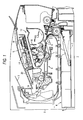
- Fig. 1 is a schematic side sectional view of an image forming apparatus according to an exemplary embodiment of the invention
- Fig. 2 is a block diagram exemplarily showing electrical configuration of the image forming apparatus
- Fig. 3 is a diagram showing a configuration of a scanner unit
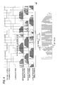
- Fig. 4 is a time chart showing waveforms of FG signals and energization on/off signals
- Figs. 5A and 5B are flowcharts showing a rotation control process
- Fig. 6 is a time chart showing a timing pattern of detection of induced voltages and light reception of a light receiving sensor
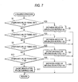
- Fig. 7 is a flowchart showing a low-speed process of a brushless motor.
- Fig. 8 is a time chart showing changes of the temperature of a fixing unit and the rotation speed of the brushless motor in a non-printing period.
- Fig. 1 is a schematic side sectional view of an image forming apparatus 1.
- the image forming apparatus 1 includes, in a body frame 2, a feeder unit 4 which feeds a sheet 3 (one example of image formed medium) such as a sheet, an image forming unit 5 which forms an image on the fed sheet 3, etc.
- a laser printer is one example of the image forming apparatus 1.
- the image forming apparatus 1 may be a monochrome laser printer or a color laser printer using two or more colors.
- the image forming apparatus may be a multi-function device having a facsimile function, a copy function, a reading function (scanner function) and the like, as far as the device has an image forming (printing) function.
- the feeder unit 4 includes a tray 6, a pressing plate 7, a pickup roller 8 and a pair of registration rollers 9, 9.
- the pressing plate 7 is swingable about a rear end portion to press the uppermost one of sheets 3 on the pressing plate 7 toward the pickup roller 8.
- the sheets 3 are picked up one at a time by rotation of the pickup roller 8.
- the transferring position is a position where a toner image on a photosensitive member 10 is transferred to the sheet 3, and where the photosensitive member 10 contacts a transferring roller 11.
- the image forming unit 5 includes a scanner unit 12, a process cartridge 13 and a fixing unit 14.
- the scanner unit 12 includes a light source 15 (see Fig. 3 ), a polygon mirror 16 (one example of a rotary polygon mirror), etc.
- a laser beam L (one example of a light beam) emitted from the light source 15 illuminates the surface of the photosensitive member 10 while being periodically deflected by the polygon mirror 16.
- the scanner unit 12 will be described later in detail.
- the process cartridge 13 includes the photosensitive member 10 (which is not limited to a drum type, but may be of a belt type), a scorotron-type charger 17, and a developing roller 18.
- the charger 17 uniformly charges the surface of the photosensitive member 10 to a positive polarity.
- the charged surface of the photosensitive member 10 is exposed to the laser beam L from the scanner unit 12 to form an electrostatic latent image.
- toner carried on the surface of the developing roller 18 is supplied to the electrostatic latent image formed on the photosensitive member 10, and the image is developed.
- the sheet 3, on which the toner image is formed, is fed to the fixing unit 14 where the toner image is thermally fixed to the sheet. Then, the sheet 3 is discharged onto a sheet discharge tray 20 through a discharge path 19.
- the image forming apparatus 1 includes a CPU 21, a ROM 22, a RAM 23, an EEPROM 24, the feeder unit 4, the image forming unit 5, a displaying unit 25, which is configured by various lamps, a liquid crystal panel, and the like, an operating unit 26 such as an input panel, a temperature sensor 27, etc.
- the image forming apparatus 1 includes a network interface (not shown) through which the image forming apparatus 1 is connected to an external apparatus, etc.
- the temperature sensor 27 is disposed in a vicinity of a heating roller 14A of the fixing unit 14.
- the temperature sensor 27 detects the temperature (one example of a temperature of the fixing unit) of the heating roller 14A and outputs a temperature detection signal corresponding to the detection temperature.
- the CPU 21 starts execution of the fixing temperature control in which the fixing unit 14 is controlled so that the temperature of the heating roller 14A is maintained at the fixable temperature value Tt [°C], based on the temperature detection signal from the temperature sensor 27.
- the CPU 21 functions as a heat controlling unit.
- the fixable temperature value Tt [°C] (for example, 200 [°C]) is a temperature at which the toner image that is transferred by the process cartridge 13 can be thermally fixed to the sheet 3.
- the scanner unit 12 includes the light source (i.e., a laser diode) 15 that emits the laser beam L, a first lens unit 30, the polygon mirror 16, a second lens unit 31, a light receiving sensor 32, a brushless motor (a polygon motor) 33, a control circuit board 34, etc.
- the light source i.e., a laser diode
- the polygon mirror 16 the polygon mirror 16
- the second lens unit 31 a light receiving sensor 32
- a brushless motor (a polygon motor) 33 a control circuit board 34, etc.
- the first lens unit 30 is configured by a collimator lens, a cylindrical lens, and the like.
- the first lens unit 30 allows the laser beam L emitted from the light source 15 to pass therethrough to irradiate the polygon mirror 16.
- the second lens unit 31 is configured by an f ⁇ lens, a cylindrical lens, and the like.
- the second lens unit 31 allows the laser beam L deflected (reflected) by the polygon mirror 16 to pass therethrough to irradiate the photosensitive member 10.
- the polygon mirror 16 is configured by, for example, a plurality of mirror surfaces (in the exemplary embodiment, six mirror surfaces).
- the polygon mirror 16 is rotated at a high speed by the brushless motor 33.
- the polygon mirror 16 periodically deflects the laser beam L emitted from the light source 15, to sequentially form scanning lines on the photosensitive member 10 through the second lens unit 31.
- the scanning lines are dot-like exposure lines corresponding to line data of image data. In the case where line data correspond to a blank portion of an image, scanning lines are not formed.
- the brushless motor 33 is a three-phase brushless DC motor.
- the brushless motor 33 has a stator 35, on which U-, V- and W-phase coils are arranged, and a rotor 36, on which field permanent magnets (in the exemplary embodiment, for example, ten poles) are arranged.
- the coils are arranged in star connection.
- the polygon mirror 16 is rotated integrally with the rotor 36.
- a driving circuit 37, a controlling circuit 38 (one example of a motor controlling unit), and the like, are mounted on the control circuit board 34.
- the driving circuit 37 rotates the brushless motor 33.
- the driving circuit 37 includes, for example, an inverter 37A (one example of an energization switching unit) to turn on or off the energizations of the coils.
- the controlling circuit 38 is configured by, for example, an ASIC.
- the controlling circuit 38 controls the light emission of the light source 15 and the rotation of the brushless motor 33 (the polygon mirror 16) based on instructions from the CPU 21.
- the light receiving sensor 32 is placed at a position where the laser beam L is received before the laser beam L deflected by the polygon mirror 16 reaches the photosensitive member 10.
- the light receiving sensor 32 is used for determining a timing of writing each scanning line with the laser beam L, receives the laser beam L emitted from the light source 15, and outputs a BD (Beam Detect) signal to the controlling circuit 38.
- the light receiving sensor 32 may be placed at a position where the laser beam L is received after the laser beam L passes through the photosensitive member 10.
- the controlling circuit 38 detects the position of the rotor 36 without using a position detecting element such as a Hall element. That is, the controlling circuit 38 detects the position of the rotor 36 on the basis of the induced voltages that are generated in the coils in accordance with rotation of the rotor 36 with respect to the stator 35.
- the induced voltage is generated in the coil.
- the impedance of each coil is different depending on the polarity of the approaching magnet, i.e., the S-pole or the N-pole. Therefore, the induced voltage has a waveform (for example, a sinusoidal wave) that is periodically changed to different levels respectively corresponding to timings of approaches of the S-pole and the N-pole. Therefore, by detecting the induced voltage, it is possible to detect the position of the rotor 36 (i.e., the polarity of the magnet approaching each coil).
- the driving circuit 37 includes three voltage detecting circuits 39, 39, 39 (one example of a voltage detecting unit) respectively corresponding to the coils.
- Each of the voltage detecting circuits 39 outputs a detection signal corresponding to the voltage difference (including the induced voltage) between the end point P of the corresponding coil (i.e., the end of the coil on the side connected to the driving circuit 37) and the neutral point O of the star connection.
- the driving circuit 37 converts each of the detection signals to a high/low signal (hereinafter, referred to as an FG signal), the level of which is inverted in accordance with a change of the induced voltage (i.e., the switching of the polarity of the magnet approaching the coil) through, for example, a comparator (not shown), and supplies the signal to the controlling circuit 38.
- the FG signal may also be called as a detection signal.
- Fig. 4 is a time chart showing waveforms of the FG signals and energization on/off signals.
- the FG signals respectively corresponding to the phases are supplied to the controlling circuit 38 as waveforms in which the phases are shifted by about 120 deg. from one another.
- the controlling circuit 38 supplies the energization on/off signals respectively corresponding to the FG signals, to the driving circuit 37 to control the turning on/off of energizations of the coils. Therefore, the rotation of the brushless motor 33 can be controlled.
- the portions where the amplitude of the PWM signal is gradually increased/decreased are energized when the coil of another phase is energized.
- the portion where the amplitude of the PWM signal is constant corresponds to a period where the coil of the own phase is energized.
- Each of the induced voltages is detected in the off period of chopping in the period where the amplitude of the PWM signal is gradually increased in the energization on period.
- the controlling circuit 38 adjusts the current amount in the energization on time by, for example, the pulse width modulation, so that the rotation speed of the brushless motor 33 can be changed. As shown in Fig. 4 , specifically, the controlling circuit 38 changes the PWM value (duty ratio) by performing chopping control on the inverter 37A during the energization on time on the basis of PWM signals, thereby changing the rotation speed of the brushless motor 33.
- the initial pulse of each of the PWM signals is set to be larger in at least one of pulse width and amplitude than the subsequent pulse group. Therefore, in the initial stage of each energization on time, a driving current which is relatively large is flown so as to enable the brushless motor 33 to be smoothly rotated. In the subsequent pulse group, the amplitude is stepwise raised, and then stepwise lowered. In on/off switching of energization, therefore, noise generation can be suppressed.
- control circuit board 34 is placed at a position separated from the place where the brushless motor 33 (the polygon mirror 16) is installed, and connected to the brushless motor 33 through only four signal lines, which are connected to the three end points P of the coil, and the neutral point O, respectively.
- Figs. 5A and 5B are flowcharts showing a process of controlling the rotation of the brushless motor 33.
- the user performs an input operation for requesting the printing process through the operating unit 26, or an external apparatus (for example, a personal computer) (not shown) transmits a print request to the image forming apparatus 1.
- the print request may include print data.
- the CPU 21 transmits rotation start instructions (an example "instructions for starting the image forming operation" in the invention) for the polygon mirror 16, to the controlling circuit 38.
- the controlling circuit 38 executes the rotation control process shown in Figs. 5A and 5B .
- a start-up process, a rotation direction detecting process, and a constant-speed process are sequentially executed.
- the controlling circuit 38 initializes a retry number stored in, for example, the EEPROM 24 to zero, and sets the PWM frequency to a low level (for example, 125 [kHz]) (S1).
- the PWM frequency is the frequency of the pulses of the PWM signals, and equal to the frequency of the chopping control during the energization on time.
- the controlling circuit 38 detects the initial position (the stop position before the start up) of the rotor 36 (S3). Specifically, the circuit controls the driving circuit 37 so that currents flow through the coils, and the magnetic fluxes in the coils are changed in accordance with the position of the rotor 36. Accompanied with this, the FG signals are changed. Therefore, the initial position of the rotor 36 can be detected based on the FG signals.
- the controlling circuit 38 executes forced energization (S5). Specifically, based on the result of the detection of the initial position, the controlling circuit 38 controls the driving circuit 37 so as to forcedly energize the coils by sequentially turning on and off the energizations of the coils, thereby attempting to rotate the rotor 36. If it is confirmed that the rotor 36 begins to be rotated on the basis of the FG signals (S6: YES), the position and rotation speed of the rotor 36 can be detected based on the FG signals because the induced voltages generated in the coils are reflected in the FG signals. If the rotation of the rotor 36 cannot be confirmed (S6: NO), the control proceeds to S27.
- S6 forced energization
- the controlling circuit 38 reads out the FG signals during the off period in the chopping control. Then, the controlling circuit 38 supplies the PWM signals of the PWM frequency which is set to the low level in S1, to the driving circuit 37 to control the on/off of energizations of the coils, and executes the rotation speed control based on the FG signals, thereby attempting to perform full scale start-up of the brushless motor 33.
- the controlling circuit 38 determines whether the rotation speed of the brushless motor 33 is stabilized by the rotation speed control based on the FG signals or not (S7). Specifically, the rotation speed of the brushless motor 33 is detected on the basis of the on/off cycle of at least one (in the exemplary embodiment, one FG signal) of the three FG signals, and it is determined whether the detected rotation speed reaches a predetermined target speed range (for example, the difference with respect to 40,000 [rpm] is equal to or smaller than a predetermined value) (one example of a speed in the image forming operation).
- a predetermined target speed range for example, the difference with respect to 40,000 [rpm] is equal to or smaller than a predetermined value
- the brushless motor 33 is not normally rotated after the forced energization in S5, the rotation speed becomes unstable, and the start-up operation is sometimes failed. In this case, the brushless motor 33 is stopped. For example, reverse currents are caused to flow to apply a braking action on the brushless motor 33. Accordingly, the brushless motor 33 can be promptly stopped, and prepared for a retry operation.
- a retrying process is performed. Specifically, the retry number is incremented by one (S25), and a part or all of start-up parameters (the frequencies of the energization on/off signals, the motor lead angle, and the PWM values (motor currents)) are changed (S9).
- the control returns to S3 to retry the start up of the brushless motor 33.
- the frequencies of the energization on/off signals, and the motor lead angle are increased (the timing of the predictive energization is advanced), or the PWM values are enhanced to increase the starting current, thereby facilitating the start up of the brushless motor 33.
- the control process is transferred (switched) to the rotation direction detecting process.
- the controlling circuit 38 executes the rotation direction detecting process to detect whether the rotor 36 rotates in a direction corresponding to the scanning direction (main scanning direction) with respect to the photosensitive member 10 or not. At this time, the controlling circuit 38 functions as "detecting unit".
- a rotation direction corresponding to the main scanning direction i.e., direction of the arrow in Fig. 3
- normal rotation direction a rotation direction opposite to the normal rotation direction
- reverse rotation direction a rotation direction opposite to the normal rotation direction
- the controlling circuit 38 controls the light source 15 so as to start the light emission (S11). Therefore, the light receiving sensor 32 periodically receives the laser beam L deflected by the polygon mirror 16, and outputs the BD signal in accordance with the light receiving timing.
- the controlling circuit 38 checks the BD signal (S13). Specifically, the controlling circuit determines whether the rotation speed of the polygon mirror 16 based on the cycle of the BD signal (hereinafter, the speed is sometimes referred to as the BD rotation speed) is within the target speed range or not. If it is determined that an abnormality such as that the BD signal cannot be detected, or that the BD rotation speed is unstable occurs (S14: YES), an error process (S27) such as stopping of the rotation control on the brushless motor 33, and displaying of information relating to the error is performed. By contrast, if it is determined that the process is normally performed (S14: NO), the control proceeds to S 15.
- S13 the controlling circuit determines whether the rotation speed of the polygon mirror 16 based on the cycle of the BD signal (hereinafter, the speed is sometimes referred to as the BD rotation speed) is within the target speed range or not. If it is determined that an abnormality such as that the BD signal cannot be detected, or that the BD rotation speed is unstable occurs (S
- the controlling circuit 38 measures the timing pattern of the detection of the induced voltage and the light reception of the light receiving sensor 32 (S15).
- the timing pattern is determined by the location relationship between the rotor 36 and the polygon mirror 16, and is different usually depending on the rotation direction. Therefore, based on the timing pattern, the rotation direction of the rotor 36 can be detected.
- a predetermined number (one or more) of the time differences between the change timing (the rising timing or the falling timing) of the FG signal and the change timing (the rising timing or the falling timing) of the BD signal are calculated.
- the calculated time differences are set as the timing pattern.
- Fig. 6 is a time chart showing the timing pattern of detection of the induced voltages and light reception of the light receiving sensor 32.
- ⁇ and ⁇ indicate a time differences from the rising timing of the FG signal and to the falling timing of the BD signal, respectively, wherein ⁇ ( ⁇ 1, ⁇ 2, ⁇ 3, ⁇ 4 and ⁇ 5) indicates a time difference in the case where the rotor 36 rotates in the normal rotation direction, and ⁇ ( ⁇ 1, ⁇ 2, ⁇ 3, ⁇ 4 and ⁇ 5) indicates a time difference in the case where the rotor 36 rotates in the reverse rotation direction.
- the controlling circuit 38 periodically calculates the time difference in the sequence of ⁇ 1, ⁇ 2, ⁇ 3, ⁇ 4 and ⁇ 5.
- the controlling circuit 38 periodically calculates the time difference in the sequence of ⁇ 1, ⁇ 2, ⁇ 3, ⁇ 4 and ⁇ 5.
- the EEPROM 24 previously stores reference pattern data.
- the reference pattern data include reference pattern data ( ⁇ 1, ⁇ 2, ⁇ 3, ⁇ 4, ⁇ 5) of the normal rotation direction and reference pattern data ( ⁇ 1, ⁇ 2, ⁇ 3, ⁇ 4, ⁇ 5) of the reverse rotation direction.
- the reference pattern data are prepared in production stage of the image forming apparatus 1 on the basis of a timing pattern that is experimentally measured in a state where the polygon mirror 16 is stably rotated within the target speed range.
- the controlling circuit 38 compares the currently measured timing pattern with the reference pattern data (reference pattern), and, based on a result of the comparison, detects the rotation direction of the rotor 36 (S17). Specifically, when the measured timing pattern data coincide with the pattern data of the normal rotation direction, it is determined that the rotor rotates in the normal rotation direction, and, when the timing pattern data coincide with the pattern data of the reverse rotation direction, it is determined that the rotor rotates in the reverse rotation direction. If it is determined that the rotor rotates in the normal rotation direction (S17: YES), the control process is transferred (switches) to the constant-speed process.
- the reverse printing mode is set in such a case that the user inputs instructions through the operating unit 26, or that the temperature (ambient temperature) measured by the temperature sensor 27 disposed in the image forming apparatus 1 is equal to or lower than a predetermined temperature, because of the following reason.
- the ambient temperature is low to some extent, there is a possibility that the lubricant in the brushless motor 33 hardens and the rotation cannot be smoothly controlled.
- a long time period is required. This is not preferable.
- the controlling circuit 38 controls the light emission of the light source 15 based on the line data in a pattern that is the reversal of that in the case where the polygon mirror 16 is rotated in the normal rotation direction. Even in the reverse rotation, an image, which is substantially identical with that in the normal rotation, can be forcedly printed. At this time, the controlling circuit 38 functions as "light emission controlling unit".
- the starting point where one surface of the polygon mirror 16 is started to be illuminated with the laser beam L from the light source 15 is indicated by Ps
- the point where the reflected light is received by the light receiving sensor 32 is indicated by Pbd
- the end point is indicated by Pg.
- the point illuminated with the laser beam L at the timing of starting the reading of line data is indicated by Qs
- the point illuminated with the laser beam L at the timing of ending the reading of line data is indicated by Qg.
- the reading of line data is started after the time period required for the laser beam L to advance the length of the line segment PbdQs has elapsed from the light receiving timing of the light receiving sensor 32.
- the reading of line data is started after the time period required for the laser beam L to advance the length of the line segment (PbdPs + PgQg) has elapsed from the light receiving timing of the light receiving sensor 32.
- the controlling circuit 38 may be configured so that, in a process of expanding image data, a dot pattern, in which line data are expanded in the sequence reverse to that in the case of the normal rotation, is formed, and the light emission of the light source 15 is controlled in accordance with the dot pattern.
- the controlling circuit may be configured so that, when a dot pattern that has undergone a normal expanding process is to be read out, the reading is performed in the sequence reverse to that in the case of the normal rotation, and the light emission of the light source 15 is controlled in accordance with the dot pattern of the reverse sequence.
- S 19 If it is determined in S 19 the reverse printing mode is not set (S 19: NO), it is determined whether the current retry number reaches the upper limit number or not (S23). If the current retry number does not reach the upper limit number (S23: NO), the retrying process is performed. Specifically, the retry number is incremented by one (S25), the control process is returned to S9, and the processes subsequent to S9 are repeated.
- the controlling circuit 38 switches the rotation speed control from one based on the FG signals to one based on the BD signal, and determines whether the rotation speed of the polygon mirror 16 is stable or not (S29). Specifically, the rotation speed of the polygon mirror 16 is detected on the basis of the on/off cycle of the BD signal, and it is determined whether the detected rotation speed is within the predetermined target speed range or not. If the detected rotation speed is outside the target-speed range (S29: NO), it is determined that the rotation speed is unstable, and the control process is returned to S25.
- the PWM frequency is switched to a high level (for example, 250 [kHz]) (S31).
- the PWM frequency is switched to a high level (for example, 250 [kHz]) (S31).
- S33 it is again determined whether the rotation speed is within the predetermined target speed range or not (S33). If the detected rotation speed is outside the target-speed range (S33: NO), it is determined that the rotation speed is unstable, and the control process is returned to S9.
- the CPU 21 causes the feeder unit 4 and the image forming unit 5 to start the printing process.
- Fig. 7 is a flowchart showing a low-speed process of the brushless motor 33
- Fig. 8 is a time chart showing changes of the temperature of the fixing unit 14 and the rotation speed of the brushless motor 33 in a non-printing period (one example of a non-image forming period) after the printing process is ended.
- Vt indicates the rotation speed (for example, 40,000 [rpm] above) in the target speed range
- Tt indicates the fixable temperature.
- the CPU 21 stops the fixing temperature control on the fixing unit 14, and informs of the end of the printing process to the controlling circuit 38.
- the CPU 21 determines the transfer to the non-printing period, by using, as a trigger, reception of a signal indicating that the rear end of the sheet 3 passes through the detection region for the rear end from, for example, a sheet discharge sensor (not shown) disposed between the fixing unit 14 and the sheet discharge tray 20.
- the controlling circuit 38 stops the light emission control on the light source 15, and performs the low-speed process.
- the controlling circuit 38 controls the inverter 37A so that the rotation speed of the brushless motor 33 is maintained at a speed which is lower than the target speed value Vt, and at which the induced voltages can be detected by the voltage detecting circuits 39.
- the controlling circuit controls the inverter 37A so that the rotation speed of the brushless motor 33 is not lowered to a speed at which the induced voltages cannot be detected by the voltage detecting circuits 39.
- the lower limit value of the speed at which the induced voltages can be detected is, for example, 2,000 [rpm] (a fourth rotation speed value Vd which will be described later).
- the controlling circuit 38 receives the next rotation start instruction during execution of the low-speed process, the controlling circuit aborts the low-speed process and transfers to S6 of the start-up process.
- the controlling circuit 38 controls, based on the FG signals, the inverter 37A so that the rotation speed of the brushless motor 33 is changed to a first rotation speed value Va (for example, 30,000 [rpm]) which is lower than the target speed value Vt [rpm].
- Va for example, 30,000 [rpm]
- Vt target speed value
- the controlling circuit 38 controls controls the inverter 37A so that the rotation speed of the brushless motor 33 is maintained at the first rotation speed value Va (for example, 30,000 [rpm]) (S3).
- the rotation speed of the brushless motor 33 is changed to a second rotation speed value Vb (for example, 20,000 [rpm]) which is lower than the first rotation speed value Va [rpm] (S7).
- the controlling circuit 38 changes the rotation speed of the brushless motor 33 to the fourth rotation speed value Vd (the lower limit value of the speed at which the induced voltages can be detected) which is lower than the third rotation speed value Vc [rpm] (S 15).
- the fourth rotation speed value Vd is slightly higher than a speed range (the hatched portion in the figure) where the induced voltages cannot be detected. For example, the value can be obtained from experiments.
- a fourth temperature value Td [°C] one example of a threshold temperature
- S13: NO a fourth temperature value
- the inverter 37A is controlled so that reverse currents for rotating the motor in the direction opposite to the current direction are caused to flow to apply a braking action on the brushless motor 33 (one example of a forcible stop) (S17), and the low-speed process is ended.
- the controlling circuit 38 when entering the non-image forming period, the controlling circuit 38 stepwisely lowers the rotation speed of the brushless motor 33 in accordance with the lowering of the temperature of the fixing unit 14 (see the solid line graph of the time chart in the lower side of Fig. 8 ).
- the relationships between the temperature of the fixing unit 14 and the rotation speed of the brushless motor 33 are as follows.
- the temperature of the fixing unit 14 is not substantially lowered. At any timing in the first step, therefore, approximate equality is requested to be attained between the time which elapses before the temperature of the fixing unit 14 is returned from the present temperature to the fixable temperature value Tt [°C] by restarting the fixing temperature control, and that which elapses before the rotation speed of the brushless motor 33 is returned by the control of the inverter 37A from the first rotation speed value Va to the target speed value Vt [rpm] (hereinafter, this relationship is referred to as "relationship 1").
- the time which elapses before the temperature of the fixing unit 14 is returned from the first temperature value Ta [°C] to the fixable temperature value Tt [°C] by restarting the fixing temperature control is approximately equal to that which elapses before the rotation speed of the brushless motor 33 is returned by the control of the inverter 37A from the second rotation speed value Vb [rpm] to the target speed value Vt [rpm] (see the broken line graph and ⁇ T1 in Fig. 8 , hereinafter, this relationship is referred to as "relationship 2").
- the controlling circuit 38 can bring the rotation speed of the brushless motor 33 to the target speed value Vt [rpm] until, at the latest, the temperature of the fixing unit 14 reaches the fixable temperature value Tt [°C].
- the thermal fixation is performed by the fixing unit 14 after the exposure by the scanner unit 12. According thereto, it is possible to prevent the electric power from being wastefully consumed by raising the temperature of the fixing unit 14 to the fixable temperature value Tt [°C] at an excessively earlier timing.
- the time which elapses before the temperature of the fixing unit 14 is returned from the second temperature value Tb [°C] to the fixable temperature value Tt [°C] by restarting the fixing temperature control is approximately equal to that which elapses before the rotation speed of the brushless motor 33 is returned by the control of the inverter 37A from the third rotation speed value Vc [rpm] to the target speed value Vt [rpm] (see the broken line graph and ⁇ T2 in Fig. 8 , hereinafter, this relationship is referred to as "relationship 3").
- the controlling circuit 38 can cause the rotation speed of the brushless motor 33 to reach the target speed value Vt [rpm] until, at the latest, the temperature of the fixing unit 14 reaches the fixable temperature value Tt [°C].
- the time which elapses before the temperature of the fixing unit 14 is returned from the third temperature value Tc [°C] to the fixable temperature value Tt [°C] by restarting the fixing temperature control is approximately equal to that which elapses before the rotation speed of the brushless motor 33 is returned by the control of the inverter 37A from the fourth rotation speed value Vd [rpm] to the target speed value Vt [rpm] (see the broken line graph and ⁇ T3 in Fig. 8 , hereinafter, this relationship is referred to as "relationship 4").
- the controlling circuit 38 can cause the rotation speed of the brushless motor 33 to reach the target speed value Vt [rpm] until, at the latest, the temperature of the fixing unit 14 reaches the fixable temperature value Tt [°C].
- the time which elapses before the temperature of the fixing unit 14 is returned from the fourth temperature value Td [°C] to the fixable temperature value Tt [°C] by restarting the fixing temperature control is approximately equal to that which elapses before the rotation speed of the brushless motor 33 is returned by the control of the inverter 37A from zero [rpm] (stop state) to the target speed value Vt [rpm] (see the broken line graph and ⁇ T4 in Fig. 8 , hereinafter, this relationship is referred to as "relationship 5").
- the controlling circuit 38 receives the next rotation start instructions due to the next print request in a state where the brushless motor 33 is stopped after stop of the low-speed process, the rotation speed of the brushless motor 33 can reach the target speed value Vt [rpm] before the temperature of the fixing unit 14 reaches the fixable temperature value Tt [°C].
- the rotation speed values Va to Vd [rpm] of the brushless motor may be predetermined fixed values.
- the values may be variable values as follows. In the last or previous printing process (for example, the first printing process after the power-on of the image forming apparatus 1), the variation amount (inclination) per unit time of the rotation speed of the brushless motor 33 by the control of the inverter 37A is measured, and the variation amount (inclination) per unit time of the temperature of the fixing unit 14 by the fixing temperature control is measured. The measured amounts are stored in, for example, the EEPROM 24.
- the controlling circuit 38 refers the inclination information of the rotation speed of the brushless motor 33 and the temperature of the fixing unit 14, and calculates the rotation speed values Va to Vd [rpm] of the brushless motor 33 which satisfy relationships 1 to 5 above.
- the rotation speed values Va to Vd [rpm] can be adjusted to adequate values.
- the low-speed process is performed in which the rotation speed of the brushless motor 33 is maintained at the rotation speed values Va to Vd [rpm] which are lower than the target speed value Vt [rpm], and at which the induced voltages can be detected by the voltage detecting circuits 39.
- the induced voltages can be detected, and the brushless motor 33 can be normally rotated based on the FG signals. Therefore, as compared with a case in which the rotation speed of the brushless motor 33 is allowed to be lowered to a level at which the induced voltages cannot be detected, the next image forming operation can be started more early.
- the low-speed process may be continued.
- this state is maintained for a long time, however, there may possibly arise an undesirable case where, for example, the power consumption for the low-speed process is increased.
- the low-speed process is stopped when the predetermined time has elapsed after the temperature of the fixing unit 14 is lowered to the fourth temperature value Td [°C], so that the power consumption is suppressed.
- the time from end of one printing process to the timing when the temperature of the fixing unit 14 is lowered below the fourth temperature value Td [°C] is one example of a reference time.
- the low-speed process is stopped when a predetermined time has elapsed after the temperature of the fixing unit 14 is lowered to the fourth temperature value Td [°C]. Therefore, the occurrence where the start of the brushless motor 33 is delayed with respect to the temperature rise of the fixing unit 14 because of a time lag (follow-up delay) of instruction transmission to the brushless motor 33 can be reduced as compared with the configuration where the low-speed process is stopped at the timing when the temperature of the fixing unit 14 is lowered to the fourth temperature value Td [°C].
- the brushless motor 33 When the brushless motor 33 is to be stopped, the brushless motor 33 is not stopped by inertia, but a braking operation applied on the motor. Therefore, even in the case where the rotation start instruction due to the next print request is received immediately after the low-speed process is stopped, the time period when the rotation is at a speed at which the induced voltages cannot be detected is short as compared with the case where the brushless motor 33 is rotated by inertia. Therefore, it is possible to increase the possibility of detecting the initial position of the rotor 36 accurately. Consequently, the rotation control of the brushless motor 33 can be performed stably and rapidly.
- the CPU 21 transfers the mode to a power saving mode in which the power consumption is more reduced than that in the printing operation. At this time, the CPU 21 functions as a transferring unit.
- the controlling circuit 38 does not perform the low-speed process.
- the process may possibly impede power saving. Thus, when the mode is transferred to the power saving mode, it is preferred that the low-speed process is not performed.
- the invention is not limited to the above-described exemplary embodiments.
- the following various embodiments are within the scope of the invention.
- those other than the most significant components of the invention are additional components and hence may be adequately omitted.
- the brushless motor is a three-phase outer-rotor type motor having star-connected coils.
- the invention is not limited thereto.
- the phase number of the motor may be two, or four or more.
- An inner-rotor type motor may be employed, or a delta-connected motor may be used. In the case of the delta connection, on the base of the inter-terminal voltages of the coils, for example, a detection signal corresponding to the induced voltage can be obtained.
- the polygon mirror 16 having six mirror surfaces, and the brushless motor 33 having ten poles are used.
- the invention is not limited thereto.
- a brushless motor having mirror surfaces, the number of which is other than six, or a brushless motor having a pole number that is other than ten may be employed.
- the minimum required number of the time difference data ⁇ , ⁇ in the rotation direction detecting process can be obtained from the surface number (N) of the polygon mirror, and the pole number (M) of the brushless motor. That is, the minimum ratio (A:B) of the surface number (N) to a half (M/2) of the pole number (M) is calculated, the smaller value (A or B) in the minimum ratio is the minimum required number. Therefore, in the case where the surface number (N) is equal to a half (M/2) of the pole number, the rotation direction can be detected from one set of time difference data.
- the rotation speed of the brushless motor 33 is controlled by using the FG signals.
- the invention is not limited thereto.
- a configuration may be employed where the number of rotations of the brushless motor 33 is monitored on the basis of the FG signals, and, under the conditions that the number of rotations reaches a reference number, various operations in the printing process such as that the light emission of the light source 15 is started, and that the sheet 3 is fed to the image forming unit 5 may be started.
- a configuration where timings of energizing the coils are controlled may be employed.
- the control process is transferred (switched) to the rotation speed control based on the BD signal.
- the rotation speed control based on the FG signals may be continued.
- influences due to noises are relatively reduced, and hence it is preferable to raise the frequency so that the follow-up property of the rotation control in the brushless motor 33 is enhanced.
- the PWM frequency is switched to a high level (S31) after it is confirmed that the rotation speed is stabilized based on the BD signal (S29 in Fig. 5B : YES).
- the invention is not limited thereto.
- the PWM frequency may be switched to a high level.
- it may be preferable to switch the PWM frequency to a high level in accordance with the above-described exemplary embodiment.
- reverse currents are caused to flow to apply a braking action on the brushless motor 33.
- the method of "forcible stop” is not limited thereto.
- a braking action may be applied on the brushless motor 33 by a mechanical (physical) contact with the rotor.
- the rotation speed of the brushless motor 33 is stepwisely lowered.
- the invention is not limited thereto.
- the rotation speed may be continuously lowered toward the fourth rotation speed value Vd [rpm], or may be lowered in one stroke to the fourth rotation speed value Vd [rpm] immediately after the end of the printing process.
- the continuation time of the low-speed process can be changed in accordance with the temperature reduction of the fixing unit 14.
- the "reference time" is not limited thereto.
- the time may be a fixed time.
- the low-speed process may be stopped when the temperature of the fixing unit 14 is lowered below the fourth temperature value Td [°C].
- Td fourth temperature value
- the motor controlling unit stops the low-speed process when a reference time has elapsed after the end of the one image forming operation even in the non-image forming period.
- the low-speed process is performed before the reference time has elapsed after the end of one image forming operation, and a state in which, the operation can be early started upon receiving an instruction for starting the next image forming operation is received, is maintained.
- this state is maintained for a long time, there may possibly arise an undesirable case where, for example, the power consumption for the low-speed process is increased.
- the low-speed process is stopped when the reference time has elapsed after the end of the one image forming operation. According thereto, it is possible to suppress the power consumption.
- the motor controlling unit forcibly stops the brushless motor to stop the low-speed process.
- the brushless motor when the low-speed process is stopped, the brushless motor is not stopped by inertia, but forcibly stopped by, for example, flowing reverse currents. Therefore, even in the case where an instruction for starting the next image forming operation is received immediately after the low-speed process is stopped, the initial position of the rotor can be accurately known as compared with the case where the brushless motor is rotated by inertia. Therefore, the rotation control of the brushless motor can be performed stably and rapidly.
- the image forming apparatus further comprises: a fixing unit that thermally fixes the toner image transferred to a recording medium from the photosensitive member; and a heat controlling unit that is configured to: during the image forming operation, perform a fixing temperature control where a temperature of the fixing unit is maintained at a fixable temperature, and in the non-image forming period, stop the fixing temperature control, wherein the reference time is a time when the temperature of the fixing unit is lowered to a threshold temperature, which is lower than the fixable temperature, in the non-image forming period (or a time when a predetermined time has elapsed after the temperature of the fixing unit is lowered to the threshold temperature).
- a time elapsing before the temperature of the fixing unit is raised from the threshold temperature to the fixable temperature by the fixing temperature control is equal to or longer than a time elapsing before the brushless motor is brought from a stop state to a rotation state in which the brushless motor rotates at the rotation speed in the image forming operation by the motor control.
- the motor controlling unit controls rotation driving of the brushless motor at a rotation speed such that: the rotation speed is lowered in accordance with temperature reduction of the fixing unit; and when an instruction for starting the image forming operation is received, the rotation speed can be returned to the rotation speed in the image forming operation by the motor control before, at a latest, the temperature of the fixing unit reaches the fixable temperature by the fixing temperature control.
- the image forming apparatus further comprises: a transferring unit which, in a case where instructions for starting a next image forming operation is not issued within a predetermined time after the image forming operation is ended, transfers the image forming apparatus to a power saving mode where a power consumption is further reduced than the image forming operation, wherein during execution of the power saving mode, the motor controlling unit does not execute the low-speed process.
- the process may possibly impede power saving. Therefore, when the mode is transferred to the power saving mode, it is preferred that the low-speed process is not performed.
Landscapes
- Physics & Mathematics (AREA)
- General Physics & Mathematics (AREA)
- Engineering & Computer Science (AREA)
- Power Engineering (AREA)
- Optics & Photonics (AREA)
- Control Of Motors That Do Not Use Commutators (AREA)
- Control Or Security For Electrophotography (AREA)
- Mechanical Optical Scanning Systems (AREA)
- Exposure Or Original Feeding In Electrophotography (AREA)
- Laser Beam Printer (AREA)
Applications Claiming Priority (1)
| Application Number | Priority Date | Filing Date | Title |
|---|---|---|---|
| JP2010078044A JP5163679B2 (ja) | 2010-03-30 | 2010-03-30 | 画像形成装置 |
Publications (3)
| Publication Number | Publication Date |
|---|---|
| EP2372464A2 true EP2372464A2 (de) | 2011-10-05 |
| EP2372464A3 EP2372464A3 (de) | 2017-11-08 |
| EP2372464B1 EP2372464B1 (de) | 2019-10-09 |
Family
ID=44170567
Family Applications (1)
| Application Number | Title | Priority Date | Filing Date |
|---|---|---|---|
| EP11157364.8A Active EP2372464B1 (de) | 2010-03-30 | 2011-03-08 | Bilderzeugungsvorrichtung |
Country Status (4)
| Country | Link |
|---|---|
| US (1) | US8547412B2 (de) |
| EP (1) | EP2372464B1 (de) |
| JP (1) | JP5163679B2 (de) |
| CN (1) | CN102207704B (de) |
Families Citing this family (13)
| Publication number | Priority date | Publication date | Assignee | Title |
|---|---|---|---|---|
| JP5888879B2 (ja) * | 2011-06-02 | 2016-03-22 | 株式会社ミツバ | 駆動装置、及び停止位置検出方法 |
| JP2013101307A (ja) * | 2011-10-20 | 2013-05-23 | Canon Inc | モータ制御装置、光学走査装置、画像形成装置およびプリント基板 |
| JP5899808B2 (ja) * | 2011-10-31 | 2016-04-06 | ブラザー工業株式会社 | 画像形成装置 |
| JP6265690B2 (ja) * | 2013-11-08 | 2018-01-24 | キヤノン株式会社 | 画像形成装置 |
| US10303080B2 (en) | 2014-04-15 | 2019-05-28 | Canon Kabushiki Kaisha | Image forming apparatus with improved timing for emitting beam detect light beam |
| JP6525571B2 (ja) * | 2014-12-05 | 2019-06-05 | キヤノン株式会社 | 画像形成装置 |
| JP6398876B2 (ja) * | 2015-05-29 | 2018-10-03 | 京セラドキュメントソリューションズ株式会社 | 画像形成装置、光走査装置、メンテナンス方法 |
| CN108270382B (zh) * | 2016-12-30 | 2021-01-22 | 杭州三花研究院有限公司 | 一种控制方法及装置 |
| CN106842870B (zh) * | 2017-03-09 | 2020-03-24 | 上海富士施乐有限公司 | 图像成形设备及定影温度控制方法 |
| CN107718912A (zh) * | 2017-11-21 | 2018-02-23 | 珠海冰河电子技术有限公司 | 一种打印机速度控制方法及装置 |
| JP6965800B2 (ja) * | 2018-03-16 | 2021-11-10 | コニカミノルタ株式会社 | 光走査装置、およびそれを備えた画像形成装置 |
| JP7292049B2 (ja) * | 2019-02-19 | 2023-06-16 | キヤノン株式会社 | モータ制御装置及び画像形成装置 |
| JP2024148794A (ja) * | 2023-04-06 | 2024-10-18 | キヤノン株式会社 | 画像形成装置 |
Citations (2)
| Publication number | Priority date | Publication date | Assignee | Title |
|---|---|---|---|---|
| JPH11129538A (ja) | 1997-11-04 | 1999-05-18 | Canon Inc | 画像形成装置 |
| JP2009088404A (ja) | 2007-10-02 | 2009-04-23 | Toshiba Corp | 半導体装置、およびその製造方法 |
Family Cites Families (16)
| Publication number | Priority date | Publication date | Assignee | Title |
|---|---|---|---|---|
| JP3179533B2 (ja) * | 1991-09-19 | 2001-06-25 | 株式会社リコー | 画像書込装置 |
| US5430362A (en) * | 1993-05-12 | 1995-07-04 | Sundstrand Corporation | Engine starting system utilizing multiple controlled acceleration rates |
| JPH0998592A (ja) * | 1995-10-03 | 1997-04-08 | Toshiba Corp | モータ駆動回路および画像形成装置 |
| JPH1115332A (ja) * | 1997-06-26 | 1999-01-22 | Sharp Corp | 画像形成装置 |
| JP3622168B2 (ja) * | 1997-07-22 | 2005-02-23 | コニカミノルタホールディングス株式会社 | 画像形成装置 |
| JPH11344913A (ja) | 1998-06-02 | 1999-12-14 | Ricoh Co Ltd | 画像形成装置 |
| JP4413470B2 (ja) * | 2002-04-11 | 2010-02-10 | シャープ株式会社 | 画像形成装置及びその初期化制御方法 |
| KR100584579B1 (ko) | 2003-04-21 | 2006-05-30 | 삼성전자주식회사 | 광주사 장치 |
| CN1270200C (zh) * | 2003-04-21 | 2006-08-16 | 三星电子株式会社 | 激光扫描单元 |
| US6822672B1 (en) * | 2003-06-24 | 2004-11-23 | Lexmark International, Inc. | Printhead and fuser standby management |
| JP4078559B2 (ja) * | 2004-03-30 | 2008-04-23 | ブラザー工業株式会社 | モータ制御装置及び画像形成装置 |
| JP4293064B2 (ja) * | 2004-06-18 | 2009-07-08 | ブラザー工業株式会社 | 画像形成装置 |
| JP2007062266A (ja) * | 2005-09-01 | 2007-03-15 | Canon Inc | 画像形成装置 |
| JP5039357B2 (ja) * | 2006-02-14 | 2012-10-03 | 株式会社リコー | ブラシレスモータの駆動制御装置、画像読取装置及び画像形成装置 |
| JP4803277B2 (ja) | 2009-03-31 | 2011-10-26 | ブラザー工業株式会社 | 画像形成装置 |
| JP4771240B2 (ja) * | 2009-03-31 | 2011-09-14 | ブラザー工業株式会社 | 画像形成装置 |
-
2010
- 2010-03-30 JP JP2010078044A patent/JP5163679B2/ja not_active Expired - Fee Related
-
2011
- 2011-03-08 EP EP11157364.8A patent/EP2372464B1/de active Active
- 2011-03-09 US US13/044,529 patent/US8547412B2/en active Active
- 2011-03-28 CN CN201110078911.2A patent/CN102207704B/zh not_active Expired - Fee Related
Patent Citations (2)
| Publication number | Priority date | Publication date | Assignee | Title |
|---|---|---|---|---|
| JPH11129538A (ja) | 1997-11-04 | 1999-05-18 | Canon Inc | 画像形成装置 |
| JP2009088404A (ja) | 2007-10-02 | 2009-04-23 | Toshiba Corp | 半導体装置、およびその製造方法 |
Also Published As
| Publication number | Publication date |
|---|---|
| EP2372464B1 (de) | 2019-10-09 |
| CN102207704A (zh) | 2011-10-05 |
| JP5163679B2 (ja) | 2013-03-13 |
| JP2011209565A (ja) | 2011-10-20 |
| CN102207704B (zh) | 2014-11-26 |
| US20110243590A1 (en) | 2011-10-06 |
| EP2372464A3 (de) | 2017-11-08 |
| US8547412B2 (en) | 2013-10-01 |
Similar Documents
| Publication | Publication Date | Title |
|---|---|---|
| EP2372464B1 (de) | Bilderzeugungsvorrichtung | |
| US8558858B2 (en) | Image forming apparatus | |
| JP5510125B2 (ja) | 画像形成装置及びブラシレスモータ制御プログラム | |
| US8259150B2 (en) | Image forming apparatus | |
| US20160342125A1 (en) | Motor control apparatus and image forming apparatus | |
| US10277152B2 (en) | Motor control apparatus, sheet conveying apparatus, image forming apparatus | |
| US8558860B2 (en) | Image forming apparatus | |
| US10666173B2 (en) | Motor control device, sheet conveying device, document feeding device, document reading device, and image forming apparatus | |
| JP5246520B2 (ja) | 光走査装置、画像形成装置及び制御プログラム | |
| US10305402B2 (en) | Motor control apparatus, sheet conveyance apparatus, document feeding apparatus, document reading apparatus, and image forming apparatus | |
| US10637382B2 (en) | Motor control apparatus, sheet conveyance apparatus, and image forming apparatus | |
| US9417553B2 (en) | Image forming apparatus | |
| US10474080B2 (en) | Image forming apparatus | |
| JP2003079184A (ja) | センサレスモータ制御装置、画像形成装置、画像形成装置の制御方法、および画像形成装置の制御プログラム | |
| US11048206B2 (en) | Motor control apparatus and image forming apparatus to prevent a motor control operation from becoming unstable | |
| US12351422B2 (en) | Image forming apparatus | |
| JP2020138811A (ja) | シート搬送装置及び画像形成装置 | |
| JP6984268B2 (ja) | ブラシレスモータ装置およびブラシレスモータ装置の制御方法 | |
| US10256756B2 (en) | Brushless motor apparatus setting mask period on the basis of comparison between voltage of specific coil and voltage of coil other than the specific coil | |
| JPH08276616A (ja) | 画像形成装置 |
Legal Events
| Date | Code | Title | Description |
|---|---|---|---|
| PUAI | Public reference made under article 153(3) epc to a published international application that has entered the european phase |
Free format text: ORIGINAL CODE: 0009012 |
|
| AK | Designated contracting states |
Kind code of ref document: A2 Designated state(s): AL AT BE BG CH CY CZ DE DK EE ES FI FR GB GR HR HU IE IS IT LI LT LU LV MC MK MT NL NO PL PT RO RS SE SI SK SM TR |
|
| AX | Request for extension of the european patent |
Extension state: BA ME |
|
| PUAL | Search report despatched |
Free format text: ORIGINAL CODE: 0009013 |
|
| AK | Designated contracting states |
Kind code of ref document: A3 Designated state(s): AL AT BE BG CH CY CZ DE DK EE ES FI FR GB GR HR HU IE IS IT LI LT LU LV MC MK MT NL NO PL PT RO RS SE SI SK SM TR |
|
| AX | Request for extension of the european patent |
Extension state: BA ME |
|
| RIC1 | Information provided on ipc code assigned before grant |
Ipc: G03G 15/04 20060101AFI20171002BHEP Ipc: G03G 15/043 20060101ALI20171002BHEP Ipc: G03G 21/16 20060101ALI20171002BHEP |
|
| STAA | Information on the status of an ep patent application or granted ep patent |
Free format text: STATUS: REQUEST FOR EXAMINATION WAS MADE |
|
| 17P | Request for examination filed |
Effective date: 20180427 |
|
| RBV | Designated contracting states (corrected) |
Designated state(s): AL AT BE BG CH CY CZ DE DK EE ES FI FR GB GR HR HU IE IS IT LI LT LU LV MC MK MT NL NO PL PT RO RS SE SI SK SM TR |
|
| GRAP | Despatch of communication of intention to grant a patent |
Free format text: ORIGINAL CODE: EPIDOSNIGR1 |
|
| STAA | Information on the status of an ep patent application or granted ep patent |
Free format text: STATUS: GRANT OF PATENT IS INTENDED |
|
| RIC1 | Information provided on ipc code assigned before grant |
Ipc: G03G 21/16 20060101ALI20190416BHEP Ipc: H02P 6/16 20160101ALI20190416BHEP Ipc: G03G 15/04 20060101AFI20190416BHEP Ipc: G03G 15/043 20060101ALI20190416BHEP Ipc: H02P 6/21 20160101ALI20190416BHEP |
|
| INTG | Intention to grant announced |
Effective date: 20190509 |
|
| GRAS | Grant fee paid |
Free format text: ORIGINAL CODE: EPIDOSNIGR3 |
|
| GRAA | (expected) grant |
Free format text: ORIGINAL CODE: 0009210 |
|
| STAA | Information on the status of an ep patent application or granted ep patent |
Free format text: STATUS: THE PATENT HAS BEEN GRANTED |
|
| AK | Designated contracting states |
Kind code of ref document: B1 Designated state(s): AL AT BE BG CH CY CZ DE DK EE ES FI FR GB GR HR HU IE IS IT LI LT LU LV MC MK MT NL NO PL PT RO RS SE SI SK SM TR |
|
| REG | Reference to a national code |
Ref country code: GB Ref legal event code: FG4D |
|
| REG | Reference to a national code |
Ref country code: CH Ref legal event code: EP |
|
| REG | Reference to a national code |
Ref country code: IE Ref legal event code: FG4D |
|
| REG | Reference to a national code |
Ref country code: DE Ref legal event code: R096 Ref document number: 602011062564 Country of ref document: DE |
|
| REG | Reference to a national code |
Ref country code: AT Ref legal event code: REF Ref document number: 1189520 Country of ref document: AT Kind code of ref document: T Effective date: 20191115 |
|
| REG | Reference to a national code |
Ref country code: NL Ref legal event code: MP Effective date: 20191009 |
|
| REG | Reference to a national code |
Ref country code: LT Ref legal event code: MG4D |
|
| REG | Reference to a national code |
Ref country code: AT Ref legal event code: MK05 Ref document number: 1189520 Country of ref document: AT Kind code of ref document: T Effective date: 20191009 |
|
| PG25 | Lapsed in a contracting state [announced via postgrant information from national office to epo] |
Ref country code: LT Free format text: LAPSE BECAUSE OF FAILURE TO SUBMIT A TRANSLATION OF THE DESCRIPTION OR TO PAY THE FEE WITHIN THE PRESCRIBED TIME-LIMIT Effective date: 20191009 Ref country code: NL Free format text: LAPSE BECAUSE OF FAILURE TO SUBMIT A TRANSLATION OF THE DESCRIPTION OR TO PAY THE FEE WITHIN THE PRESCRIBED TIME-LIMIT Effective date: 20191009 Ref country code: AT Free format text: LAPSE BECAUSE OF FAILURE TO SUBMIT A TRANSLATION OF THE DESCRIPTION OR TO PAY THE FEE WITHIN THE PRESCRIBED TIME-LIMIT Effective date: 20191009 Ref country code: ES Free format text: LAPSE BECAUSE OF FAILURE TO SUBMIT A TRANSLATION OF THE DESCRIPTION OR TO PAY THE FEE WITHIN THE PRESCRIBED TIME-LIMIT Effective date: 20191009 Ref country code: PT Free format text: LAPSE BECAUSE OF FAILURE TO SUBMIT A TRANSLATION OF THE DESCRIPTION OR TO PAY THE FEE WITHIN THE PRESCRIBED TIME-LIMIT Effective date: 20200210 Ref country code: BG Free format text: LAPSE BECAUSE OF FAILURE TO SUBMIT A TRANSLATION OF THE DESCRIPTION OR TO PAY THE FEE WITHIN THE PRESCRIBED TIME-LIMIT Effective date: 20200109 Ref country code: FI Free format text: LAPSE BECAUSE OF FAILURE TO SUBMIT A TRANSLATION OF THE DESCRIPTION OR TO PAY THE FEE WITHIN THE PRESCRIBED TIME-LIMIT Effective date: 20191009 Ref country code: SE Free format text: LAPSE BECAUSE OF FAILURE TO SUBMIT A TRANSLATION OF THE DESCRIPTION OR TO PAY THE FEE WITHIN THE PRESCRIBED TIME-LIMIT Effective date: 20191009 Ref country code: LV Free format text: LAPSE BECAUSE OF FAILURE TO SUBMIT A TRANSLATION OF THE DESCRIPTION OR TO PAY THE FEE WITHIN THE PRESCRIBED TIME-LIMIT Effective date: 20191009 Ref country code: GR Free format text: LAPSE BECAUSE OF FAILURE TO SUBMIT A TRANSLATION OF THE DESCRIPTION OR TO PAY THE FEE WITHIN THE PRESCRIBED TIME-LIMIT Effective date: 20200110 Ref country code: NO Free format text: LAPSE BECAUSE OF FAILURE TO SUBMIT A TRANSLATION OF THE DESCRIPTION OR TO PAY THE FEE WITHIN THE PRESCRIBED TIME-LIMIT Effective date: 20200109 Ref country code: PL Free format text: LAPSE BECAUSE OF FAILURE TO SUBMIT A TRANSLATION OF THE DESCRIPTION OR TO PAY THE FEE WITHIN THE PRESCRIBED TIME-LIMIT Effective date: 20191009 |
|
| PG25 | Lapsed in a contracting state [announced via postgrant information from national office to epo] |
Ref country code: RS Free format text: LAPSE BECAUSE OF FAILURE TO SUBMIT A TRANSLATION OF THE DESCRIPTION OR TO PAY THE FEE WITHIN THE PRESCRIBED TIME-LIMIT Effective date: 20191009 Ref country code: HR Free format text: LAPSE BECAUSE OF FAILURE TO SUBMIT A TRANSLATION OF THE DESCRIPTION OR TO PAY THE FEE WITHIN THE PRESCRIBED TIME-LIMIT Effective date: 20191009 Ref country code: IS Free format text: LAPSE BECAUSE OF FAILURE TO SUBMIT A TRANSLATION OF THE DESCRIPTION OR TO PAY THE FEE WITHIN THE PRESCRIBED TIME-LIMIT Effective date: 20200224 |
|
| PG25 | Lapsed in a contracting state [announced via postgrant information from national office to epo] |
Ref country code: AL Free format text: LAPSE BECAUSE OF FAILURE TO SUBMIT A TRANSLATION OF THE DESCRIPTION OR TO PAY THE FEE WITHIN THE PRESCRIBED TIME-LIMIT Effective date: 20191009 |
|
| REG | Reference to a national code |
Ref country code: DE Ref legal event code: R097 Ref document number: 602011062564 Country of ref document: DE |
|
| PG2D | Information on lapse in contracting state deleted |
Ref country code: IS |
|
| PG25 | Lapsed in a contracting state [announced via postgrant information from national office to epo] |
Ref country code: IS Free format text: LAPSE BECAUSE OF FAILURE TO SUBMIT A TRANSLATION OF THE DESCRIPTION OR TO PAY THE FEE WITHIN THE PRESCRIBED TIME-LIMIT Effective date: 20200209 Ref country code: RO Free format text: LAPSE BECAUSE OF FAILURE TO SUBMIT A TRANSLATION OF THE DESCRIPTION OR TO PAY THE FEE WITHIN THE PRESCRIBED TIME-LIMIT Effective date: 20191009 Ref country code: CZ Free format text: LAPSE BECAUSE OF FAILURE TO SUBMIT A TRANSLATION OF THE DESCRIPTION OR TO PAY THE FEE WITHIN THE PRESCRIBED TIME-LIMIT Effective date: 20191009 Ref country code: EE Free format text: LAPSE BECAUSE OF FAILURE TO SUBMIT A TRANSLATION OF THE DESCRIPTION OR TO PAY THE FEE WITHIN THE PRESCRIBED TIME-LIMIT Effective date: 20191009 Ref country code: DK Free format text: LAPSE BECAUSE OF FAILURE TO SUBMIT A TRANSLATION OF THE DESCRIPTION OR TO PAY THE FEE WITHIN THE PRESCRIBED TIME-LIMIT Effective date: 20191009 |
|
| PLBE | No opposition filed within time limit |
Free format text: ORIGINAL CODE: 0009261 |
|
| STAA | Information on the status of an ep patent application or granted ep patent |
Free format text: STATUS: NO OPPOSITION FILED WITHIN TIME LIMIT |
|
| PG25 | Lapsed in a contracting state [announced via postgrant information from national office to epo] |
Ref country code: SK Free format text: LAPSE BECAUSE OF FAILURE TO SUBMIT A TRANSLATION OF THE DESCRIPTION OR TO PAY THE FEE WITHIN THE PRESCRIBED TIME-LIMIT Effective date: 20191009 Ref country code: IT Free format text: LAPSE BECAUSE OF FAILURE TO SUBMIT A TRANSLATION OF THE DESCRIPTION OR TO PAY THE FEE WITHIN THE PRESCRIBED TIME-LIMIT Effective date: 20191009 Ref country code: SM Free format text: LAPSE BECAUSE OF FAILURE TO SUBMIT A TRANSLATION OF THE DESCRIPTION OR TO PAY THE FEE WITHIN THE PRESCRIBED TIME-LIMIT Effective date: 20191009 |
|
| 26N | No opposition filed |
Effective date: 20200710 |
|
| PG25 | Lapsed in a contracting state [announced via postgrant information from national office to epo] |
Ref country code: MC Free format text: LAPSE BECAUSE OF FAILURE TO SUBMIT A TRANSLATION OF THE DESCRIPTION OR TO PAY THE FEE WITHIN THE PRESCRIBED TIME-LIMIT Effective date: 20191009 |
|
| REG | Reference to a national code |
Ref country code: CH Ref legal event code: PL |
|
| PG25 | Lapsed in a contracting state [announced via postgrant information from national office to epo] |
Ref country code: SI Free format text: LAPSE BECAUSE OF FAILURE TO SUBMIT A TRANSLATION OF THE DESCRIPTION OR TO PAY THE FEE WITHIN THE PRESCRIBED TIME-LIMIT Effective date: 20191009 |
|
| REG | Reference to a national code |
Ref country code: BE Ref legal event code: MM Effective date: 20200331 |
|
| PG25 | Lapsed in a contracting state [announced via postgrant information from national office to epo] |
Ref country code: LU Free format text: LAPSE BECAUSE OF NON-PAYMENT OF DUE FEES Effective date: 20200308 |
|
| PG25 | Lapsed in a contracting state [announced via postgrant information from national office to epo] |
Ref country code: IE Free format text: LAPSE BECAUSE OF NON-PAYMENT OF DUE FEES Effective date: 20200308 Ref country code: CH Free format text: LAPSE BECAUSE OF NON-PAYMENT OF DUE FEES Effective date: 20200331 Ref country code: LI Free format text: LAPSE BECAUSE OF NON-PAYMENT OF DUE FEES Effective date: 20200331 |
|
| PG25 | Lapsed in a contracting state [announced via postgrant information from national office to epo] |
Ref country code: BE Free format text: LAPSE BECAUSE OF NON-PAYMENT OF DUE FEES Effective date: 20200331 |
|
| PG25 | Lapsed in a contracting state [announced via postgrant information from national office to epo] |
Ref country code: TR Free format text: LAPSE BECAUSE OF FAILURE TO SUBMIT A TRANSLATION OF THE DESCRIPTION OR TO PAY THE FEE WITHIN THE PRESCRIBED TIME-LIMIT Effective date: 20191009 Ref country code: MT Free format text: LAPSE BECAUSE OF FAILURE TO SUBMIT A TRANSLATION OF THE DESCRIPTION OR TO PAY THE FEE WITHIN THE PRESCRIBED TIME-LIMIT Effective date: 20191009 Ref country code: CY Free format text: LAPSE BECAUSE OF FAILURE TO SUBMIT A TRANSLATION OF THE DESCRIPTION OR TO PAY THE FEE WITHIN THE PRESCRIBED TIME-LIMIT Effective date: 20191009 |
|
| PG25 | Lapsed in a contracting state [announced via postgrant information from national office to epo] |
Ref country code: MK Free format text: LAPSE BECAUSE OF FAILURE TO SUBMIT A TRANSLATION OF THE DESCRIPTION OR TO PAY THE FEE WITHIN THE PRESCRIBED TIME-LIMIT Effective date: 20191009 |
|
| P01 | Opt-out of the competence of the unified patent court (upc) registered |
Effective date: 20230529 |
|
| PGFP | Annual fee paid to national office [announced via postgrant information from national office to epo] |
Ref country code: DE Payment date: 20240130 Year of fee payment: 14 Ref country code: GB Payment date: 20240201 Year of fee payment: 14 |
|
| PGFP | Annual fee paid to national office [announced via postgrant information from national office to epo] |
Ref country code: FR Payment date: 20240213 Year of fee payment: 14 |
|
| REG | Reference to a national code |
Ref country code: DE Ref legal event code: R119 Ref document number: 602011062564 Country of ref document: DE |
|
| GBPC | Gb: european patent ceased through non-payment of renewal fee |
Effective date: 20250308 |
|
| PG25 | Lapsed in a contracting state [announced via postgrant information from national office to epo] |
Ref country code: DE Free format text: LAPSE BECAUSE OF NON-PAYMENT OF DUE FEES Effective date: 20251001 |
|
| PG25 | Lapsed in a contracting state [announced via postgrant information from national office to epo] |
Ref country code: GB Free format text: LAPSE BECAUSE OF NON-PAYMENT OF DUE FEES Effective date: 20250308 |
|
| PG25 | Lapsed in a contracting state [announced via postgrant information from national office to epo] |
Ref country code: FR Free format text: LAPSE BECAUSE OF NON-PAYMENT OF DUE FEES Effective date: 20250331 |