EP2372809B1 - Batterie secondaire - Google Patents
Batterie secondaire Download PDFInfo
- Publication number
- EP2372809B1 EP2372809B1 EP11157535.3A EP11157535A EP2372809B1 EP 2372809 B1 EP2372809 B1 EP 2372809B1 EP 11157535 A EP11157535 A EP 11157535A EP 2372809 B1 EP2372809 B1 EP 2372809B1
- Authority
- EP
- European Patent Office
- Prior art keywords
- safety valve
- output terminal
- terminal member
- positive
- negative
- Prior art date
- Legal status (The legal status is an assumption and is not a legal conclusion. Google has not performed a legal analysis and makes no representation as to the accuracy of the status listed.)
- Not-in-force
Links
Images



Classifications
-
- H—ELECTRICITY
- H01—ELECTRIC ELEMENTS
- H01M—PROCESSES OR MEANS, e.g. BATTERIES, FOR THE DIRECT CONVERSION OF CHEMICAL ENERGY INTO ELECTRICAL ENERGY
- H01M50/00—Constructional details or processes of manufacture of the non-active parts of electrochemical cells other than fuel cells, e.g. hybrid cells
- H01M50/10—Primary casings; Jackets or wrappings
- H01M50/147—Lids or covers
-
- H—ELECTRICITY
- H01—ELECTRIC ELEMENTS
- H01M—PROCESSES OR MEANS, e.g. BATTERIES, FOR THE DIRECT CONVERSION OF CHEMICAL ENERGY INTO ELECTRICAL ENERGY
- H01M10/00—Secondary cells; Manufacture thereof
- H01M10/05—Accumulators with non-aqueous electrolyte
- H01M10/052—Li-accumulators
- H01M10/0525—Rocking-chair batteries, i.e. batteries with lithium insertion or intercalation in both electrodes; Lithium-ion batteries
-
- H—ELECTRICITY
- H01—ELECTRIC ELEMENTS
- H01M—PROCESSES OR MEANS, e.g. BATTERIES, FOR THE DIRECT CONVERSION OF CHEMICAL ENERGY INTO ELECTRICAL ENERGY
- H01M50/00—Constructional details or processes of manufacture of the non-active parts of electrochemical cells other than fuel cells, e.g. hybrid cells
- H01M50/10—Primary casings; Jackets or wrappings
- H01M50/102—Primary casings; Jackets or wrappings characterised by their shape or physical structure
- H01M50/103—Primary casings; Jackets or wrappings characterised by their shape or physical structure prismatic or rectangular
-
- H—ELECTRICITY
- H01—ELECTRIC ELEMENTS
- H01M—PROCESSES OR MEANS, e.g. BATTERIES, FOR THE DIRECT CONVERSION OF CHEMICAL ENERGY INTO ELECTRICAL ENERGY
- H01M50/00—Constructional details or processes of manufacture of the non-active parts of electrochemical cells other than fuel cells, e.g. hybrid cells
- H01M50/30—Arrangements for facilitating escape of gases
- H01M50/342—Non-re-sealable arrangements
- H01M50/3425—Non-re-sealable arrangements in the form of rupturable membranes or weakened parts, e.g. pierced with the aid of a sharp member
-
- H—ELECTRICITY
- H01—ELECTRIC ELEMENTS
- H01M—PROCESSES OR MEANS, e.g. BATTERIES, FOR THE DIRECT CONVERSION OF CHEMICAL ENERGY INTO ELECTRICAL ENERGY
- H01M50/00—Constructional details or processes of manufacture of the non-active parts of electrochemical cells other than fuel cells, e.g. hybrid cells
- H01M50/50—Current conducting connections for cells or batteries
- H01M50/543—Terminals
-
- H—ELECTRICITY
- H01—ELECTRIC ELEMENTS
- H01M—PROCESSES OR MEANS, e.g. BATTERIES, FOR THE DIRECT CONVERSION OF CHEMICAL ENERGY INTO ELECTRICAL ENERGY
- H01M2220/00—Batteries for particular applications
- H01M2220/20—Batteries in motive systems, e.g. vehicle, ship, plane
-
- Y—GENERAL TAGGING OF NEW TECHNOLOGICAL DEVELOPMENTS; GENERAL TAGGING OF CROSS-SECTIONAL TECHNOLOGIES SPANNING OVER SEVERAL SECTIONS OF THE IPC; TECHNICAL SUBJECTS COVERED BY FORMER USPC CROSS-REFERENCE ART COLLECTIONS [XRACs] AND DIGESTS
- Y02—TECHNOLOGIES OR APPLICATIONS FOR MITIGATION OR ADAPTATION AGAINST CLIMATE CHANGE
- Y02E—REDUCTION OF GREENHOUSE GAS [GHG] EMISSIONS, RELATED TO ENERGY GENERATION, TRANSMISSION OR DISTRIBUTION
- Y02E60/00—Enabling technologies; Technologies with a potential or indirect contribution to GHG emissions mitigation
- Y02E60/10—Energy storage using batteries
-
- Y—GENERAL TAGGING OF NEW TECHNOLOGICAL DEVELOPMENTS; GENERAL TAGGING OF CROSS-SECTIONAL TECHNOLOGIES SPANNING OVER SEVERAL SECTIONS OF THE IPC; TECHNICAL SUBJECTS COVERED BY FORMER USPC CROSS-REFERENCE ART COLLECTIONS [XRACs] AND DIGESTS
- Y02—TECHNOLOGIES OR APPLICATIONS FOR MITIGATION OR ADAPTATION AGAINST CLIMATE CHANGE
- Y02P—CLIMATE CHANGE MITIGATION TECHNOLOGIES IN THE PRODUCTION OR PROCESSING OF GOODS
- Y02P70/00—Climate change mitigation technologies in the production process for final industrial or consumer products
- Y02P70/50—Manufacturing or production processes characterised by the final manufactured product
-
- Y—GENERAL TAGGING OF NEW TECHNOLOGICAL DEVELOPMENTS; GENERAL TAGGING OF CROSS-SECTIONAL TECHNOLOGIES SPANNING OVER SEVERAL SECTIONS OF THE IPC; TECHNICAL SUBJECTS COVERED BY FORMER USPC CROSS-REFERENCE ART COLLECTIONS [XRACs] AND DIGESTS
- Y02—TECHNOLOGIES OR APPLICATIONS FOR MITIGATION OR ADAPTATION AGAINST CLIMATE CHANGE
- Y02T—CLIMATE CHANGE MITIGATION TECHNOLOGIES RELATED TO TRANSPORTATION
- Y02T10/00—Road transport of goods or passengers
- Y02T10/60—Other road transportation technologies with climate change mitigation effect
- Y02T10/70—Energy storage systems for electromobility, e.g. batteries
Definitions
- the present invention relates to a secondary battery having a safety valve.
- secondary batteries represented by lithium-ion batteries have been applied not only to mobile objects such as hybrid electric vehicles (HEVs), electric vehicles (EVs), forklifts, and excavators but also to industrial purposes such as uninterruptible power supplies (UPSs) and storages of electric power generated by solar power generation.
- HEVs hybrid electric vehicles
- EVs electric vehicles
- UPSs uninterruptible power supplies
- storages of electric power generated by solar power generation As the usage of the secondary batteries is spread, it is sought to increase the capacity and the energy density of the secondary batteries.
- the secondary batteries include nickel-cadmium batteries, nickel-hydrogen batteries, and lithium-ion batteries.
- the lithium-ion secondary batteries are particularly suitable for increasing the energy density, and are currently actively developed.
- the nickel-hydrogen batteries and the lithium-ion secondary batteries include, as their main constituent elements, a negative electrode having a negative current collecting member and a negative active material layer held on a surface of the negative current collecting member, a separator holding an electrolyte, and a positive electrode having a positive current collecting member and a positive active material layer held on a surface of the positive current collecting member.
- the nickel-hydrogen batteries include a nickel oxide in the positive active material layer of the positive electrode and a hydrogen-storing alloy in the negative active material layer of the negative electrode.
- the lithium-ion secondary batteries include a lithium metal oxide in the positive active material of the positive electrode and a carbon material such as graphite in the negative active material layer of the negative electrode.
- the secondary batteries are roughly classified into those having a cylindrical structure, in which an elongated negative electrode, an elongated separator, and an elongated positive electrode are sequentially layered to make layered structure and the layers are wound into a swirling shape, and those having a layered structure, in which a rectangular negative electrode, a rectangular separator, and a rectangular positive electrode are layered.
- the layered batteries in which the rectangular negative electrode, the rectangular separator, and the rectangular positive electrode are layered, are more suitable for increasing the energy density per volume than the batteries having a cylindrical structure, which include a greater volume of space that is not relevant to power generation such as an axial core for winding up the elongated negative electrode, the elongated separator, and the elongated positive electrode.
- the layered batteries require no axial core for wind-up and readily allow a positive output terminal and a negative output terminal to be disposed on an identical surface of a battery case, such batteries can reduce a volume of space including the parts that does not contribute to power generation.
- the battery case of such secondary batteries includes a case body receiving an electrode group and a lid plate having a positive output terminal member and a negative output terminal member and tightly sealing the case body.
- the output positive terminal member and the output negative terminal member are connected to the electrode group including the negative electrode, the separator, and the positive electrode before the case body is sealed with the lid plate.
- the positive output terminal member and the negative output terminal member each include a terminal body and a terminal base portion formed at the base of the terminal body. A portion of each output terminal member that is exposed to the outside of the battery case is referred to as the terminal portion, and a portion of each output terminal member that is received inside the battery case is referred to as the terminal base portion. Generally, the terminal base portion of each output terminal member is electrically connected to the electrode group.
- the lid plate After an assembly with the lid plate into which the positive output terminal member and the negative output terminal member and the electrode group are assembled is received in the case body, the lid plate is attached to an opening portion of the case body via an insulating member. After the assembly with the lid plate is inserted into the opening portion of the case body, the lid plate and the case body are sealed against each other.
- the separator, the positive electrode, and the negative electrode which are constituent elements of the battery assembly, are impregnated with an electrolyte.
- the battery case is provided with a safety mechanism such as a safety valve. If a rupture, an ignition, or the like occurs in batteries with a high energy density and a large capacity because of wrong use such as overcharging or a short circuit due to mixing of foreign matter, greater damage may be caused compared to the conventional batteries.
- Japanese Patent Application Publication No. 2002-8616 discloses a safety valve, which is disposed at a lid plate to which a positive terminal member and a negative terminal member are attached.
- Japanese Patent No. 3573295 proposes a safety valve disposed on a side surface of a battery case.
- Japanese Patent No. 3573295 also discloses that a gas discharge hole (safety valve) is disposed at a shadow area obtained by projecting a wound area of a swirling electrode group onto a side wall of a battery case to allow produced gas to be smoothly discharged to the outside of the battery through the gas discharge hole along the winding axis, in order that the produced gas can be smoothly discharged to the outside of the battery case when the safety valve is opened.
- 4233671 discloses a cylindrical battery in which an electrode column is disposed at the center of a circular sealing plate, a plurality of explosion protection valves are provided at the sealing plate around the electrode column, and a joint surface for a lead is provided on the outer peripheral surface of the electrode column at a circumferential position that is not in the directions in which the plurality of explosion protection valves are disposed so that the plurality of explosion protection valves and the lead are disposed not to overlap with each other as viewed from the direction perpendicular to the sealing plate.
- a battery with a large capacity discharges a large amount of gas when ruptured, and thus requires a safety valve with as large an area as possible. If the area of the safety valve is too small for the battery capacity, the amount of gas to be discharged to the outside of the battery case is small for the amount of generated gas. Therefore, the internal pressure of the battery case may not stop rising even if the safety valve is actuated, which may lead to a breakage of the battery case itself.
- the safety valve and the terminal members should be increased in size along with an increase in capacity of the secondary battery.
- the safety valve is disposed on a side surface of the battery case to allow a smooth flow of gas produced during an abnormality as in the secondary battery disclosed in Japanese Patent No. 3573295 , it is necessary to form a hole or the like in a portion of the battery case other than the lid plate on which the positive output terminal member and the negative output terminal member are disposed, which increases the cost. It is also necessary to provide a space for releasing gas or a space for wiring outside a wall surface of the battery case on which the safety valve is disposed and a wall surface of the battery case on which the output terminal members are disposed. In the secondary battery disclosed in Japanese Patent No. 3573295 , however, the safety valve and the terminal members for external output are disposed at different wall surfaces of the battery case. Therefore, it is necessary to provide a free space around two wall surfaces of the battery case, which significantly restricts installation of the battery or the like compared to the case where the safety valve and the output terminal members are disposed on the same wall surface.
- the electrode column serving as the electrode terminal is disposed at the center of each end of the battery case. Therefore, the safety valves may not be disposed at the center of an end portion of the battery case.
- the size of each safety valve is limited to a value obtained by subtracting the radius of the electrode column from the radius of the cylindrical battery case or less. Therefore, it is difficult to increase the diameter of the safety valves if the size of the electrode column is increased.
- the output terminals are disposed at both ends of the battery case, which requires a large volume of space for elements other than the power generating elements.
- the energy density may not be enhanced compared to the case where the output terminals are provided on an identical wall surface of the battery case.
- gas produced between two adjacent metal current collecting members is discharged along the winding axis.
- the electrode group with a layered structure uses rectangular metal current collecting members, and thus produced gas tends to spread in all directions in the battery case to fill the battery case. Therefore, when the electrode group with a layered structure is used, it is desired to more immediately discharge gas to the outside of the battery case.
- the present invention seeks to provide a secondary battery which may have a large capacity and a high energy density that excels in safety by reliably discharging gas from the battery when a safety valve is actuated or operated.
- a secondary battery according to the present invention comprises an electrode group and a battery case.
- the electrode group includes one or more negative electrodes each having a negative current collecting member and a negative active material held on the negative current collecting member, one or more positive electrodes each having a positive current collecting member and a positive active material held on the positive current collecting member, and a separator holding an electrolyte.
- the one or more negative electrodes and the one or more positive electrodes are alternately layered via the separator.
- the battery case includes a case body having an opening portion and receiving the electrode group and a lid plate closing the opening portion.
- the secondary battery according to the present invention also includes: a negative output terminal member provided with the lid plate and electrically connected to the one or more negative electrodes; a positive output terminal member provided with the lid plate and electrically connected to the one or more positive electrodes; and a safety valve.
- the safety valve is provided at the lid plate at a position between the negative output terminal member and the positive output terminal member, and includes an opening area to be opened when the internal pressure of the battery case rises to a predetermined pressure or higher.
- the safety valve is disposed to partially overlap with an imaginary center line passing through the center between the negative output terminal member and the positive output terminal member and extending along a plate surface of the lid plate to divide the lid plate into two halves.
- the safety valve, the negative output terminal member, and the positive output terminal member are configured to satisfy the following two conditions.
- a first condition is that the minimum distance from the imaginary center line to respective end edges of the negative output terminal member and the positive output terminal member on the side of the safety valve is equal to or less than the minimum distance from the imaginary center line to the outermost end edge of the safety valve.
- a second condition is that a shadow area obtained by projecting the opening area of the safety valve onto an imaginary plane extending along the plate surface of the lid plate does not overlap with respective shadow areas obtained by projecting the negative output terminal member and the positive output terminal member onto the imaginary plane.
- the shadow area of the opening area of the safety valve does not overlap with the respective shadow areas of the positive output terminal member and the negative output terminal member even if such output terminal members are increased in size. Therefore, a passage for releasing gas from the electrode group to the safety valve is secured to smoothly discharge gas produced during an abnormality to the outside of the battery case. As a result, it is possible to provide a battery structure with a large capacity that ensures enhanced safety.
- the safety valve is disposed in the lid plate which is located in a direction perpendicular to a layering direction in which the positive electrodes and the negative electrodes in the electrode group are layered.
- This allows gas produced between the positive current collecting member and the negative current collecting member of the electrode group to pass through a space between the positive current collecting member and the negative current collecting member to be discharged in the direction perpendicular to the layering direction.
- it is possible to provide a battery structure that ensures enhanced safety by smoothly discharging gas.
- the lid plate may have a rectangular profile, and the safety valve may have a circular profile.
- the safety valve is preferably disposed with its center located at the intersection of the two diagonal lines of the lid plate.
- An electrical connection tab may be formed at an end portion of the positive current collecting member facing the lid plate.
- An electrical connection tab may be formed at an end portion of the negative current collecting member facing the lid plate.
- the electrical connection tab of the positive current collecting member and the positive output terminal member may be connected to each other at a position outside the profile of the safety valve.
- the electrical connection tab of the negative current collecting member and the negative output terminal member may be connected to each other at a position outside the profile of the safety valve.
- the electrical connection tab of the positive current collecting member and the positive output terminal member may be connected to each other at positions along two imaginary lines, in three imaginary lines dividing the plate surface of the lid plate into four equal quarters in the layering direction of the electrode group, excluding the center imaginary line in the three imaginary lines.
- the electrical connection tab of the negative current collecting member and the negative output terminal member may also be connected to each other at positions along the two imaginary lines. With this configuration, it is not necessary to make the tabs longer than necessary.
- the positive output terminal member and the negative output terminal member may be disposed symmetrically to each other with respect to the imaginary center line.
- the safety valve may be a circular metal foil provided with a groove pattern formed to open in a surface of the safety valve not facing the electrode group.
- the safety valve may also be a circular metal foil provided with a groove pattern formed to entirely open the opening area of the safety valve when the safety valve is in operation, in which case the effect of the present invention is enhanced.
- the safety valve may be a circular metal foil formed with a groove pattern.
- the groove pattern may be configured to have a portion passing through the center of the safety valve and an arcuate portion extending along the outer peripheral portion of the safety valve.
- the groove pattern may have a continuous unicursal design with no intersection.
- the groove pattern having a continuous unicursal design, it is possible to provide a battery structure with a large capacity and enhanced safety in which a crack in the groove pattern is smoothly propagated and in which fragments of the safety valve are not scattered by the gas discharge pressure.
- the groove pattern should have a shape generally corresponding to the shape of an alphabetic letter "s" or "e” or a swirling shape.
- any shape similar to such shapes provides the same effect to a greater or lesser degree.
- Fig. 1 is a projected view of a battery according to an embodiment of the present invention as viewed from the direction where a lid plate cab be seen.
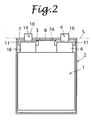
- Fig. 2 is a transparent view of the battery of Fig. 1 as viewed from the direction where a side surface can be seen.
- a layered lithium-ion secondary battery with a battery capacity of 200 Ah is shown.
- an electrode group 1 includes a negative electrode having a rectangular negative current collecting member (copper) and a negative active material layer held on a surface of the negative current collecting member, a separator holding an electrolyte, and a positive electrode having a rectangular positive current collecting member (aluminum) and a positive active material layer held on a surface of the positive current collecting member.
- the positive electrode and the negative electrode are alternately layered via the separator.
- the dimension, such as the width, of the electrode group 1 and the number of positive electrodes and negative electrodes which are layered are determined by the required battery capacity.
- a battery case 2 has a rectangular parallelepiped shape to receive the electrode group 1 which has a substantially rectangular layered structure.
- rectangular layered batteries In contrast to cylindrical secondary batteries in which the elongated metal current collecting members and the elongated separator are wound into a cylindrical shape and then inserted into a cylindrical battery case, rectangular layered batteries have a rectangular parallelepiped battery case and do not have an axial core for wind-up or the like, thereby providing an enhanced energy density per volume.
- Metal materials such as aluminum and stainless steel, for example, are preferred as the material of the battery case 2 in terms of the mechanical strength.
- the material of the battery case 2 is not limited to metal materials, and the battery case 2 may be formed by resins, which are not eroded by the electrolyte, such as fluorine resins, polyethylene, polypropylene, epoxy resins, POM, and PEEK, for example.
- the battery case 2 made of a resin is light in weight for the low density of the material compared to the battery case 2 made of a metal.
- the battery case 2 made of a resin is weak in strength, and has a low thermal conductivity which leads to low heat radiation.
- An electrical connection tab 6 is unitarily formed at an end portion of the positive current collecting member, which is one of the elements constituting the electrode group 1, in the longitudinal direction.
- An electrical connection tab 16 is unitarily formed at an end portion of the negative current collecting member in the longitudinal direction.
- the tab 6 and a positive output terminal member 4, and the tab 16 and a negative output terminal member 14, are secured to each other by ultrasonic welding. Electrically connected components including the positive output terminal member 4 and the negative output terminal member 14 refer to parts which comprise secondary electrically connected components.
- the secondary electrically connected components are, for example, external output terminals for the positive and negative electrodes, tab fusion bonding plates that are joined to the tabs, pressing plates that press the tab fusion bonding plates against the external output terminals, and metal fastening members such as nuts, washers, and bolts.
- the positive output terminal member 4 and the negative output terminal member 14 each include a terminal portion 10 having a portion exposed from a lid plate 7 to the outside of the battery case 2 and a terminal base portion 11 received inside the battery case 2.
- the electrode group 1 includes positive electrodes each including the tab 16 and negative electrodes each including the tab 16. The number of positive electrodes and that of negative electrodes are determined by the capacity of the battery.
- the electrically connected components including the output terminal member 4, 14 may be constructed the secondary electrically connected components.
- the tabs 6,16 are joined to the electrically connected components by ultrasonic welding in groups using the secondary components (not shown).
- the tabs 6 and the positive output terminal member 4, and the tabs 16 and the negative output terminal member 14, may be electrically connected to each other by swaging, crimping, or the like other than the ultrasonic welding.
- the electrode group 1 is not shown to facilitate understanding of the positional relationship between respective shadow areas 9, 19 obtained by projecting the positive output terminal member 4 and the negative output terminal member 14 onto an imaginary plane S including a plate surface of the lid plate 7 and a shadow area 8 obtained by projecting an opening area of a safety valve 3 in operation onto the imaginary plane S.
- the layering direction corresponds to the direction in which the short sides of the rectangular lid plate 7 extend, or the perpendicular direction in which the plurality of tabs 6 (16) are arranged.
- the electrical connection tabs 6 of the positive current collecting members and the positive output terminal member 4 are connected to each other at positions along two imaginary lines L1 and L3, in three imaginary lines L1 to L3 dividing the lid plate 7 into four equal quarters in the layering direction of the electrode group 1, excluding the center imaginary line L2 in the three imaginary lines L1 to L3.
- the electrical connection tabs 16 of the negative current collecting members and the negative output terminal member 14 are also connected to each other at positions along the two imaginary lines L1 and L3.
- the safety valve 3 is disposed to partially overlap with an imaginary center line CL passing through the center between the positive output terminal member 4 and the negative output terminal member 14 and extending along the plate surface of the lid plate 7 to divide the lid plate 7 into two halves.
- the imaginary center line CL extends to intersect the imaginary line L2, which passes through the center of the positive output terminal member 4 and the center of the negative output terminal member 14, at a right angle at the position where the imaginary line L2 is divided into two halves.
- the minimum distance from the imaginary center line CL to the outermost circumference or the outermost end edge of the safety valve 3 is defined as "b".
- the minimum distance from the imaginary center line CL to the end edge of the positive output terminal member 4 or the negative output terminal member 14 on the safety valve 3 side is defined as "a".
- the minimum distance a from the imaginary center line CL to the end edge of the positive output terminal member 4 or the negative output terminal member 14 on the safety valve 3 side is set to be longer than the distance b from the imaginary center line CL to the outermost end edge (outermost circumference) of the safety valve 3 in order to prevent the safety valve 3 from overlapping with the positive output terminal member 4 or the negative output terminal member 14.
- the minimum distance a from the imaginary center line CL to the respective end edges of the negative output terminal member 14 and the positive output terminal member 4 on the safety valve 3 side is set to be shorter than the distance b from the imaginary center line CL to the outermost end edge of the safety valve 3. That is, the respective end edges of the negative output terminal member 14 and the positive output terminal member 4 are disposed closer to the imaginary center line CL than the outermost end edge of the safety valve 3.
- the shadow area of the opening area of the safety valve 3 does not overlap with the respective shadow areas of the positive output terminal member 4 and the negative output terminal member 14 even if the output terminal members are increased in size. Therefore, a sufficient passage for releasing gas from the electrode group 1 to the safety valve 3 is secured.
- the safety valve 3 can adequately function to smoothly discharge gas produced during an abnormality to the outside of the battery case 2.
- the tabs 6, 16 and the positive output terminal member 4 and the negative output terminal member 14 are connected to each other at positions on the side of the outer periphery of the lid plate 7 with respect to the outermost end edge (outer circumference) of the safety valve 3. This ensures a large area for joint with the tabs 6, 16, which suppresses an increase of an electric resistance due to increased battery capacity.
- the lid plate 7 is provided with holes through which the respective terminal portions 10 of the positive output terminal member 4 and the negative output terminal member 14 pass.
- the positive output terminal member 4 and the negative output terminal member 14 are fixed to the back surface of the lid plate 7 via a seal member (not shown), an electric insulating member (not shown), and a fastening member (not shown). It is a matter of course that the connection between the lid plate 7 and the positive output terminal member 4 and the negative output terminal member 14 is not limited thereto.
- the lid plate 7, the positive output terminal member 4, and the negative output terminal member 14 may integrally be formed by insert molding. In this case, the positive output terminal member 4 and the negative output terminal member 14 are electrically insulated from the lid plate 7.
- the safety valve 3 has a circular profile with its center disposed at the intersection of the two diagonal lines of the rectangular lid plate 7.
- the opening area of the safety valve 3 is cracked along a groove pattern so that the gas in the battery is released to the outside of the battery case 2 through the safety valve 3.
- the safety valve 3 is disposed in a direction perpendicular to the layering direction in which the positive electrode and the negative electrode in the electrode group 1 are layered so that the produced gas passes between the positive electrode and the negative electrode and then is smoothly discharged through the safety valve 3.
- the profile of the safety valve 3 is not limited to a perfect circle shape, and may be a shape including an arcuate portion such as an oval shape, a rectangular shape with rounded corners, or an egg-like shape.
- the safety valve 3 is a thin circular plate made of stainless steel and formed with a groove pattern by etching. Upon a predetermined pressure, the safety valve 3 is cracked at a portion of the groove pattern to be opened along the groove pattern. The cracking pressure is adjusted in accordance with the relationship between the outer circumference of the safety valve 3 and the geometry of the groove pattern. The groove pattern will be described in detail later.
- the method of forming a groove in the safety valve 3 is not limited to etching, and the groove may be formed by pressurization, laser processing, or cutting.
- a through hole 7A which is larger than the opening area of the safety valve 3, is formed in the lid plate 7 at a position where the safety valve 3 is to be attached. Then, the safety valve 3 is attached to the back surface of the lid plate 7 by laser welding.
- the structure for providing the safety valve 3 at the lid plate 7 is not limited to the technique employed in the embodiment. For example, the safety valve 3 may be directly mechanically formed at the lid plate 7 by cutting or pressurization.
- the material of the safety valve 3 is not limited to stainless steel, and may be a metal such as aluminum, nickel or the like or a resin such as a fluorine resin, polyethylene, or polypropylene. Also, the safety valve 3 may be made from a material that is impervious to water and is the same as or is easily joined to the material of the lid plate 7.
- the distance from the center to the outermost portion of the groove pattern 5 corresponds to the opening diameter of the safety valve 3.
- the positive output terminal member 4 and the negative output terminal member 14 are disposed symmetrically to each other in the horizontal direction with respect to the imaginary center line CL passing through the center of the lid plate 7. Owing to this configuration, current may equally be distributed to flow from the positive electrode and the negative electrode to the positive output terminal member 4 and the negative output terminal member 14.
- the shadow area 8 obtained by projecting the opening area of the safety valve 3 in operation onto the imaginary plane S including the plate surface of the lid plate 7 does not overlap with the respective shadow areas 9, 19 obtained by projecting the positive output terminal member 4 and the negative output terminal member 14 onto the imaginary plane S.
- the shadow area 8 obtained by projecting the opening area of the safety valve 3 in operation onto the imaginary plane S does not overlap with all or any part of the respective shadow areas 9, 19 obtained by projecting the positive output terminal member 4 and the negative output terminal member 14 onto the imaginary plane S.
- the gas produced in the battery case 2, primarily in the electrode group 1 may smoothly pass through a space from the electrode group 1 to the opening area of the safety valve 3 attached to the lid plate 7 without being hindered by the positive output terminal member 4 and the negative output terminal member 14. This makes it possible to provide a battery structure that ensures enhanced safety by ensuring reliable gas discharge.
- a battery according to the present embodiment was prepared and subjected to an overcharge test to measure the internal pressure, the temperature, the battery voltage, and the current.
- the safety valve was opened at a predetermined pressure to discharge gas. Once the safety valve was opened, the safety valve or the electrically connected components were not clogged by any part of the metal current collecting members and abrupt variations in pressure such as bumping was not observed. Then, the internal pressure decreased as the time elapsed. Thus, the secondary battery of the present embodiment was confirmed as being highly safe.
- Fig. 3 is a projected plan view of a battery according to a second embodiment of the present invention as viewed from above a lid plate 7'.
- the secondary battery according to the second embodiment is a lithium-ion secondary battery of a layered structure and with a capacity of 250 Ah which is 1.25 times larger than that of the battery according to the first embodiment.
- the capacity density has been improved by improving the positive and negative active material layers.
- the dimensions of the lid plate 7' are the same as the lid plate 7 according to the first embodiment.
- a portion of a terminal base portion 11' around a terminal portion 10' which is a terminal for external connection that stands up vertically with respect to the lid plate 7', is dented or curved toward the terminal portion 10'.
- a shadow area 8' obtained by projecting the opening area of a safety valve 3' in operation onto the imaginary plane S including the plate surface of the lid plate 7' does not overlap with respective shadow areas 9', 19' obtained by projecting the positive output terminal member 4' and the negative output terminal member 14' onto the imaginary plane S.
- the width of the lid plate 7' is the same as that of the lid plate 7 according to the first embodiment.
- the distance between the positive output terminal member 4' and the negative output terminal member 14' disposed at the lid plate 7' is the same as that in the battery according to the first embodiment.
- the diameter of the safety valve 3' and the diameter of the opening area have been increased.
- the safety valve 3' is located at the intersection of the two diagonal lines of the lid plate 7'.
- the minimum distance a from the imaginary center line CL of the lid plate 7' to the respective end edges of the positive output terminal member 4' and the negative output terminal member 14' on the safety valve 3' side is set to be shorter than the distance b from the imaginary center line CL to the outermost end edge of the safety valve 3'. That is, the respective end edges of the positive output terminal member 4' and the negative output terminal member 14' are disposed closer to the center of the lid plate 7' than the outermost end edge of the safety valve 3'. This ensures a large area for joint with tabs 6', 16', thereby suppressing an increase of an electric resistance due to increased battery capacity.
- the tabs 6', 16' which are portions for electrical connection extending from the electrode group, are respectively joined to the positive output terminal member 4' and the negative output terminal member 14' at positions between the outer periphery of the lid plate 7' and the outer circumference of the safety valve 3'. Since there are many tabs 6' , 16' , the tabs 6' , 16' are respectively joined to the positive electrode and the negative electrode each at four positions.
- the tabs 6', 16' and the positive output terminal member 4' and the negative output terminal member 14' are connected to each other at positions between the outer periphery of the lid plate 7' and the outer circumference of the safety valve 3', it is possible to increase the diameter of the safety valve 3'.
- the safety valve 3' has a circular profile with its center disposed at the intersection of the two diagonal lines of the lid plate 7'.
- the electrical connection tabs 6',16' are formed at end portions of the metal current collecting members.
- the electrical connection tabs 6',16' and the positive and negative output terminal members 4',14' are respectively connected to each other at positions between the outer periphery of the lid plate 7' and the outer circumference of the safety valve 3'.
- the shadow areas obtained by projecting the positive output terminal member 4' and the negative output terminal member 14' onto the imaginary plane S and the shadow area obtained by projecting the safety valve 3' onto the imaginary plane S including the plate surface of the lid plate 7' do not overlap with each other. This makes it possible to form the safety valve 3' with a circular profile over a wide area, and to ensure the safety for a battery with an increased capacity.
- Fig. 4 shows an example of the safety valve 3'.
- Fig. 4 shows a safety valve 31 with a groove pattern 51 generally corresponding to the shape of an alphabetic letter "s".
- the groove pattern 51 has a straight portion passing through the center of the safety valve 31 and arcuate portions extending along the outer periphery of the safety valve 31, and has a continuous unicursal design.
- the groove forming the groove pattern 51 is formed to open toward the lid plate 7'. This allows the groove pattern 51 to be cracked to form an opening portion when the safety valve 31 is in operation. That is, the area of the opening portion corresponds to the shadow area 8' obtained by projecting the opening portion of the safety valve 31 in operation onto the plane of the lid plate.
- the groove pattern 51 does not have a closed shape so that no fragments of the safety valve 31 are scattered when the safety valve 31 is opened. That is, even after the groove in the groove pattern 51 is opened, portions of the safety valve around the opened groove are left as a part of the lid plate 7'
- the groove forming the groove pattern can be formed by etching.
- the safety valve is formed of a stainless steel foil, which is the same as the material of the safety valve according to the first embodiment. Besides stainless steel, a material that is impervious to water and that is the same as or is easily joined to the material of the lid plate may be used as in the first embodiment.
- the groove pattern is preferably shaped to have a larger diameter when the safety valve is opened at a location closer to the outer periphery of the safety valve.
- the safety valve is affected to a greater degree by thermal strain or the like that occurs when the safety valve is attached to the lid plate, which may cause fluctuations in cracking pressure.
- the straight portion passes through the center of the safety valve 31. Therefore, a crack is initially caused at a portion of the groove in the vicinity of the center of the safety valve 31, and propagated along the groove to the arcuate portions continuously formed along the outer periphery of the safety valve 31, which opens the safety valve 31. This makes it possible to reduce fluctuations in cracking pressure, and to increase the opening diameter.
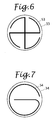
- the groove pattern is not limited to that shown in Fig. 4 , and may be a pattern having a portion passing through the center of the safety valve and an arcuate portion extending along the outer periphery of the safety valve, such as those shown in Figs. 5 , 6, and 7 , for example.
- Fig. 5 shows a safety valve 32 with a swirling groove pattern 52 that starts at the center of the safety valve 32.
- a crack is caused at a portion of the groove in the vicinity of the center of the safety valve 32, and is propagated along the groove to a portion of the groove at the outermost circumference of the safety valve 32, which opens the safety valve 32.
- Fig. 6 shows a safety valve 33 with a groove pattern 53 having a plus sign portion and arcuate portions provided at the four ends of the plus sign portion.
- Fig. 7 shows a safety valve 34 with a groove pattern 54 generally corresponding to the shape of an alphabetic letter "e".
- the safety valves of Figs. 4 to 7 provide substantially the same opening diameter when the safety valves are in operation.
- the groove patterns of Figs. 4, 5 , and 7 each have a continuous unicursal design with no intersection.
- a crack in the groove pattern is propagated in a uniquely determined direction, which causes the safety valve to reliably open.
- the groove pattern is not specifically limited to a shape of the alphabetic letter "s", a swirling shape, a shape of a plus sign with extended end portions, or a shape of the alphabetic letter "e”, and may have an arcuate portion to provide the effect described above.
- the safety valve formed by a circular metal foil formed with a groove pattern including a portion passing through the center of the safety valve and an arcuate portion extending along the outer periphery of the safety valve and having a continuous unicursal design, it is possible to reduce fluctuations in opening pressure of the safety valve, and to open the safety valve at a predetermined pressure. This makes it possible to provide a battery structure that ensures enhanced safety.
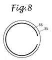
- a safety valve 35 with a groove pattern 55 not passing through the center of the safety valve 35 as shown in Fig. 8 was prepared and subjected to a cracking test. Consequently, it was found that fluctuations in cracking pressure of the groove patterns of Figs. 4 to 7 were smaller than fluctuations in cracking pressure of the groove pattern 55 of Fig. 8 .
- a secondary battery according to the second embodiment was prepared and subjected to an overcharge test to measure the internal pressure, the temperature, the battery voltage, and the current.
- the secondary battery was continuously charged until the safety valve was actuated.
- the safety valve was opened at a predetermined pressure to discharge gas.
- the safety valve or the electrically connected components were not clogged by any part of the metal current collecting members and abrupt variations in pressure such as bumping was not observed.
- the internal pressure decreased as the time elapsed.
- the secondary battery of the present embodiment was confirmed as being highly safe.
- the battery capacity for the same volume of the electrode group is increased by improving the characteristics of the active materials as in the second embodiment, it is possible to increase the area of the safety valve without increasing the dimensions of the battery case, thereby ensuring safety.
- the battery capacity is increased by changing the number of electrodes which are layered using metal current collecting members with the same dimensions, it is possible to increase the area of the safety valve without increasing the width of the battery case, thereby ensuring safety.
Landscapes
- Chemical & Material Sciences (AREA)
- Chemical Kinetics & Catalysis (AREA)
- Electrochemistry (AREA)
- General Chemical & Material Sciences (AREA)
- Engineering & Computer Science (AREA)
- Materials Engineering (AREA)
- Manufacturing & Machinery (AREA)
- Gas Exhaust Devices For Batteries (AREA)
- Connection Of Batteries Or Terminals (AREA)
- Secondary Cells (AREA)
Claims (9)
- Batterie secondaire, comprenant :un groupe d'électrodes (1) incluant une ou plusieurs électrodes négatives ayant chacune un élément de collecte de courant négatif et un matériau actif négatif retenu sur l'élément de collecte de courant négatif, une ou plusieurs électrodes positives ayant chacune un élément de collecte de courant positif et un matériau actif positif retenu sur l'élément de collecte de courant positif, et un séparateur retenant un électrolyte, une ou plusieurs électrodes négatives et une ou plusieurs électrodes positives étant disposées en couches alternativement via le séparateur ;un boîtier de batterie (2) incluant un corps de boîtier ayant une portion d'ouverture et recevant le groupe d'électrodes (1) et une plaque de couvercle (7) fermant la portion d'ouverture ;un élément terminal à sortie négative (14) muni de la plaque de couvercle (7) et connecté électriquement à une ou plusieurs électrodes négatives précitées ;un élément terminal à sortie positive (4) muni de la plaque de couvercle (7) et connecté électriquement à une ou plusieurs électrodes positives précitées ; etune vanne de sécurité (3) réalisée à la plaque de couvercle (7) à une position entre l'élément terminal à sortie négative (14) et l'élément terminal à sortie positive (4) et incluant une zone d'ouverture à ouvrir lorsque la pression interne du boîtier de batterie (2) augmente à une pression prédéterminée ou au-delà, caractérisée en ce que :la vanne de sécurité (3) est disposée pour se chevaucher partiellement avec une ligne central imaginaire (CL) passant à travers le centre entre l'élément terminal à sortie négative (14) et l'élément terminal à sortie positive (4) et s'étendant le long d'une surface de plaque de la plaque de couvercle (7) pour diviser la plaque de couvercle (7) en deux moitiés ; etla vanne de sécurité (3), l'élément terminal à sortie négative (14) et l'élément terminal à sortie positive (4) sont configurés de telle sorte que la distance minimale (a) de la ligne centrale imaginaire (CL) à des bords d'extrémité respectifs de l'élément terminal à sortie négative (14) et de l'élément terminal à sortie positive (4) au côté de la vanne de sécurité (3) est égale ou inférieure à la distance minimale (b) de la ligne centrale imaginaire (CL) au bord d'extrémité le plus extérieur de la vanne de sécurité (3), et de sorte qu'une zone d'ombre (8) obtenue par la projection de la zone d'ouverture de la vanne de sécurité (3) sur un plan imaginaire (S) s'étendant le long de la surface de plaque de la plaque de couvercle (7) ne se chevauche pas avec des zones d'ombre respectives (9, 19) obtenues par la projection de l'élément terminal à sortie négative (14) et de l'élément terminal à sortie positive (4) sur le plan imaginaire (S).
- Batterie secondaire selon la revendication 1, dans laquelle
la vanne de sécurité (3) est disposée dans la plaque de couvercle (7) qui est située dans une direction perpendiculaire à la direction de mise en couche dans laquelle les électrodes positives et les électrodes négatives dans le groupe d'électrodes (1) sont disposées en couches. - Batterie secondaire selon la revendication 1, dans laquelle :la plaque de couvercle (7) a un profil rectangulaire ;la vanne de sécurité (3) a un profil circulaire, son centre se situant à une intersection de deux lignes diagonales de la plaque de couvercle (7) ;une patte de connexion électrique (6) est formée à une portion d'extrémité de l'élément de collecte de courant positif faisant face à la plaque de couvercle (7) ;une patte de connexion électrique (16) est formée à une portion d'extrémité de l'élément de collecte de courant négatif faisant face à la plaque de couvercle (7) ;la patte de connexion électrique (6) de l'élément de collecte de courant positif et l'élément terminal à sortie positive (4) sont connectés l'un à l'autre à une position à l'extérieur du profil de la vanne de sécurité (3) ; etla patte de connexion électrique (16) de l'élément de collecte de courant négatif et l'élément terminal à sortie négative (14) sont connectés l'un à l'autre à une position à l'extérieur du profilé de la vanne de sécurité (3).
- Batterie secondaire selon la revendication 3, dans laquelle :la patte de connexion électrique (6) de l'élément de collecte de courant positif et l'élément terminal à sortie positive (4) sont connectés l'un à l'autre à des positions le long de deux lignes imaginaires (L1, L3), dans trois lignes imaginaires (L1, L2, L3) divisant la surface de la plaque de couvercle (7) en quatre quartiers égaux dans la direction de disposition des couches du groupe d'électrodes (1), excluant la ligne imaginaire centrale (L2) dans les trois lignes imaginaires (L1, L2, L3) ; etla patte de connexion électrique (16) de l'élément de collecte de courant négatif et l'élément terminal à sortie négative (14) sont connectés l'un à l'autre à des positions le long des deux lignes imaginaires (L1, L3).
- Batterie secondaire selon la revendication 3, dans laquelle
l'élément terminal à sortie positive (4) et l'élément terminal à sortie négative (14) sont disposés d'une manière symétrique l'un à l'autre par rapport à la ligne centrale imaginaire (CL). - Batterie secondaire selon la revendication 3, dans laquelle
la vanne de sécurité (3) est une feuille de métal circulaire présentant un motif rainuré (5) formé pour s'ouvrir dans une surface de la vanne de sécurité (3) ne faisant pas face au groupe d'électrodes (1). - Batterie secondaire selon la revendication 3, dans laquelle
la vanne de sécurité (3) est une feuille de métal circulaire présentant un motif rainuré (5) formé pour ouvrir entièrement la zone d'ouverture de la vanne de sécurité (3) lorsque la vanne de sécurité (3) est en fonctionnement. - Batterie secondaire selon la revendication 1, dans laquelle
la vanne de sécurité (31) est une feuille de métal circulaire présentant un motif rainuré (51) ayant une portion passant à travers le centre de la vanne de sécurité (31) et une portion arquée s'étendant le long de la portion périphérique extérieure de la vanne de sécurité (31), le motif rainuré (51) ayant un motif uni-cursif continu sans intersection. - Batterie secondaire selon la revendication 8, dans laquelle
le motif rainuré (52, 53, 54) a une forme correspondant généralement à la forme d'une lettre alphabétique "s", une forme correspondant généralement à la forme d'une lettre alphabétique "e", une forme tourbillonnante ou une forme similaire à de telles formes.
Applications Claiming Priority (1)
| Application Number | Priority Date | Filing Date | Title |
|---|---|---|---|
| JP2010058224A JP5703573B2 (ja) | 2010-03-15 | 2010-03-15 | 二次電池 |
Publications (2)
| Publication Number | Publication Date |
|---|---|
| EP2372809A1 EP2372809A1 (fr) | 2011-10-05 |
| EP2372809B1 true EP2372809B1 (fr) | 2013-08-28 |
Family
ID=44279755
Family Applications (1)
| Application Number | Title | Priority Date | Filing Date |
|---|---|---|---|
| EP11157535.3A Not-in-force EP2372809B1 (fr) | 2010-03-15 | 2011-03-09 | Batterie secondaire |
Country Status (5)
| Country | Link |
|---|---|
| US (1) | US9065098B2 (fr) |
| EP (1) | EP2372809B1 (fr) |
| JP (1) | JP5703573B2 (fr) |
| KR (1) | KR101821675B1 (fr) |
| CN (1) | CN102195024B (fr) |
Families Citing this family (30)
| Publication number | Priority date | Publication date | Assignee | Title |
|---|---|---|---|---|
| EP2765631B1 (fr) * | 2011-10-06 | 2016-07-20 | Toyota Jidosha Kabushiki Kaisha | Batterie assemblée et procédé de production pour batterie assemblée |
| KR101577330B1 (ko) * | 2011-11-01 | 2015-12-15 | 히다치 막셀 가부시키가이샤 | 밀폐형 전지 |
| JP2013182784A (ja) * | 2012-03-01 | 2013-09-12 | Hitachi Maxell Ltd | 密閉型電池 |
| JP2013182785A (ja) * | 2012-03-01 | 2013-09-12 | Hitachi Maxell Ltd | 密閉型電池 |
| JP2013239274A (ja) * | 2012-05-14 | 2013-11-28 | Hitachi Maxell Ltd | 密閉型電池 |
| JP6016478B2 (ja) * | 2012-06-28 | 2016-10-26 | ニチコン株式会社 | 電解コンデンサ用の圧力弁、および、これを用いた電解コンデンサ |
| CN104685692A (zh) * | 2012-09-28 | 2015-06-03 | 三洋电机株式会社 | 非水电解质二次电池 |
| JP2014107147A (ja) * | 2012-11-28 | 2014-06-09 | Toyota Industries Corp | 蓄電装置 |
| CN105074960B (zh) * | 2013-04-16 | 2018-01-09 | 株式会社早出长野 | 电池壳体 |
| JP6044465B2 (ja) * | 2013-06-25 | 2016-12-14 | 株式会社豊田自動織機 | 蓄電装置 |
| JP6044482B2 (ja) * | 2013-07-30 | 2016-12-14 | 株式会社豊田自動織機 | 蓄電装置の製造方法 |
| JP6015595B2 (ja) * | 2013-08-22 | 2016-10-26 | 株式会社豊田自動織機 | 蓄電装置 |
| US10256444B2 (en) * | 2014-07-15 | 2019-04-09 | Sanyo Electric Co., Ltd. | Electricity storage device |
| CN104091902B (zh) * | 2014-07-15 | 2016-07-06 | 惠州威健锂能电子有限公司 | 一种热收缩塑料薄膜外壳一次性锂离子电池及其制造方法 |
| JP6394894B2 (ja) * | 2014-12-19 | 2018-09-26 | 株式会社豊田自動織機 | 蓄電装置 |
| JP6891955B2 (ja) * | 2017-06-15 | 2021-06-18 | 株式会社村田製作所 | 二次電池、電池パック、電動車両、電力貯蔵システム、電動工具および電子機器 |
| JP6852629B2 (ja) * | 2017-09-12 | 2021-03-31 | トヨタ自動車株式会社 | 蓄電装置 |
| JP2019075214A (ja) * | 2017-10-12 | 2019-05-16 | 株式会社Gsユアサ | 蓄電素子、及び蓄電素子の製造方法 |
| JP7029924B2 (ja) * | 2017-10-17 | 2022-03-04 | 株式会社Gsユアサ | 蓄電素子及び蓄電モジュール |
| WO2021124828A1 (fr) * | 2019-12-16 | 2021-06-24 | 株式会社村田製作所 | Batterie secondaire, procédé de fabrication de batterie secondaire, dispositif électronique et outil électrique |
| CN114946061A (zh) * | 2020-02-17 | 2022-08-26 | 株式会社村田制作所 | 二次电池、电子设备和电动工具 |
| CN115843400B (zh) * | 2020-09-30 | 2025-11-04 | 松下知识产权经营株式会社 | 电池组 |
| CN112670596B (zh) * | 2020-12-16 | 2022-06-07 | 曙鹏科技(深圳)有限公司 | 电芯、电芯卷绕方法及电池 |
| CN113745746B (zh) * | 2021-11-03 | 2022-04-29 | 深圳小木科技有限公司 | 一种盖板易组装的新能源环保电池 |
| CN114759297A (zh) * | 2022-04-20 | 2022-07-15 | 广东维都利新能源有限公司 | 一种焊接盖板的硬壳电池及制造方法 |
| CN115295935A (zh) * | 2022-08-12 | 2022-11-04 | 广汽埃安新能源汽车有限公司 | 动力电池和电动车 |
| EP4564540A1 (fr) * | 2023-12-01 | 2025-06-04 | Automotive Cells Company SE | Cellule de stockage d'énergie comprenant une membrane d'évacuation pré-découpee |
| JP1776700S (ja) * | 2023-12-05 | 2024-07-30 | 電池ケース | |
| JP1776652S (ja) * | 2023-12-05 | 2024-07-30 | 電池ケース | |
| JP1776699S (ja) * | 2023-12-05 | 2024-07-30 | 電池ケース |
Family Cites Families (20)
| Publication number | Priority date | Publication date | Assignee | Title |
|---|---|---|---|---|
| US2401448A (en) * | 1943-09-16 | 1946-06-04 | Electric Storage Battery Co | Filling and venting structure for storage batteries |
| JP3573295B2 (ja) | 1994-04-28 | 2004-10-06 | 日本電池株式会社 | 角型密閉式電池 |
| JP4355865B2 (ja) * | 1998-11-10 | 2009-11-04 | 株式会社ジーエス・ユアサコーポレーション | 電池 |
| JP2000182591A (ja) * | 1998-12-15 | 2000-06-30 | Japan Storage Battery Co Ltd | 電 池 |
| JP2000251949A (ja) * | 1999-02-24 | 2000-09-14 | Sanyo Electric Co Ltd | 密閉型蓄電池 |
| JP4233671B2 (ja) | 1999-03-01 | 2009-03-04 | パナソニック株式会社 | 非水電解液二次電池 |
| JP4486223B2 (ja) * | 2000-06-16 | 2010-06-23 | 三菱重工業株式会社 | 非水電解質二次電池の安全弁の形成方法及び非水電解質二次電池 |
| JP3840896B2 (ja) * | 2000-12-01 | 2006-11-01 | 新神戸電機株式会社 | 角形非水電解液電池 |
| JP4955865B2 (ja) * | 2001-06-05 | 2012-06-20 | ミヤマツール株式会社 | 密閉型電池の封口板及びその製造方法 |
| JP4191411B2 (ja) * | 2002-01-11 | 2008-12-03 | 三菱重工業株式会社 | 二次電池容器およびその製造方法 |
| JP2005190708A (ja) * | 2003-12-24 | 2005-07-14 | Sanyo Electric Co Ltd | 角形電池 |
| JP4797335B2 (ja) * | 2004-04-28 | 2011-10-19 | 株式会社Gsユアサ | 電池 |
| KR100599748B1 (ko) * | 2004-06-23 | 2006-07-12 | 삼성에스디아이 주식회사 | 이차 전지와 이차 전지의 캡 조립체 및 이에 사용되는안전밸브 설치 방법 |
| JP2006216435A (ja) * | 2005-02-04 | 2006-08-17 | Nec Tokin Tochigi Ltd | 密閉型電池 |
| JP2006324178A (ja) * | 2005-05-20 | 2006-11-30 | Kyushu Electric Power Co Inc | 二次電池 |
| JP2007157678A (ja) * | 2005-05-23 | 2007-06-21 | Matsushita Electric Ind Co Ltd | ラミネート電池の安全機構 |
| JP4996857B2 (ja) * | 2006-01-24 | 2012-08-08 | トヨタ自動車株式会社 | 電池 |
| JP5146110B2 (ja) * | 2008-05-29 | 2013-02-20 | トヨタ自動車株式会社 | 電池、車両及び電池搭載機器 |
| JP2010040328A (ja) * | 2008-08-05 | 2010-02-18 | Sanyo Electric Co Ltd | 密閉型電池 |
| JP2010097769A (ja) * | 2008-10-15 | 2010-04-30 | Mitsubishi Heavy Ind Ltd | 電池端子、二次電池、電池端子の製造方法及び二次電池の製造方法 |
-
2010
- 2010-03-15 JP JP2010058224A patent/JP5703573B2/ja not_active Expired - Fee Related
-
2011
- 2011-03-07 CN CN201110053581.1A patent/CN102195024B/zh not_active Expired - Fee Related
- 2011-03-07 KR KR1020110019972A patent/KR101821675B1/ko not_active Expired - Fee Related
- 2011-03-09 EP EP11157535.3A patent/EP2372809B1/fr not_active Not-in-force
- 2011-03-10 US US13/044,887 patent/US9065098B2/en not_active Expired - Fee Related
Also Published As
| Publication number | Publication date |
|---|---|
| US9065098B2 (en) | 2015-06-23 |
| KR20110103859A (ko) | 2011-09-21 |
| EP2372809A1 (fr) | 2011-10-05 |
| JP2011192550A (ja) | 2011-09-29 |
| US20110311847A1 (en) | 2011-12-22 |
| CN102195024B (zh) | 2015-09-30 |
| JP5703573B2 (ja) | 2015-04-22 |
| KR101821675B1 (ko) | 2018-01-24 |
| CN102195024A (zh) | 2011-09-21 |
Similar Documents
| Publication | Publication Date | Title |
|---|---|---|
| EP2372809B1 (fr) | Batterie secondaire | |
| EP2254176B1 (fr) | Batterie rechargeable | |
| EP2197064B1 (fr) | Élément d'orifice de batterie secondaire | |
| JP6003655B2 (ja) | 二次電池 | |
| CN103227310B (zh) | 方形二次电池 | |
| US8883332B2 (en) | Rechargeable secondary battery | |
| US7655353B2 (en) | Battery | |
| CN103227309B (zh) | 方形二次电池 | |
| US8557420B2 (en) | Secondary battery having tab with blowing agent and manufacturing method thereof | |
| KR100914115B1 (ko) | 이차전지 | |
| US20220328945A1 (en) | Bus member, battery and power consumption device | |
| KR19990031352A (ko) | 전지의 안전장치 | |
| KR101546545B1 (ko) | 파우치형 리튬이차전지 | |
| KR101890844B1 (ko) | 최외곽 전극의 구조 및 집전체의 재질에 의해 사용 안전성이 향상된 전극 조립체 및 상기 전극 조립체를 갖는 리튬이온 이차전지 | |
| KR102752402B1 (ko) | 전지 셀 및 그의 제조 방법, 제조 시스템, 전지 및 전기 장치 | |
| JP6020879B2 (ja) | 外装容器、蓄電素子 | |
| EP4632907A2 (fr) | Bloc-batterie | |
| EP4661199A1 (fr) | Élément de batterie, bloc-batterie et véhicule le comprenant | |
| EP4539197A1 (fr) | Batterie cylindrique et bloc-batterie et véhicule la comprenant | |
| EP4564500A1 (fr) | Plaque collectrice de courant et unité de batterie comprenant une plaque collectrice de courant | |
| EP4621953A1 (fr) | Bloc-batterie | |
| EP4718593A1 (fr) | Élément de batterie et module de batterie | |
| KR20190060636A (ko) | 최외곽 전극의 구조 및 집전체의 재질에 의해 사용 안전성이 향상된 전극 조립체 및 상기 전극 조립체를 갖는 리튬이온 이차전지 |
Legal Events
| Date | Code | Title | Description |
|---|---|---|---|
| PUAI | Public reference made under article 153(3) epc to a published international application that has entered the european phase |
Free format text: ORIGINAL CODE: 0009012 |
|
| AK | Designated contracting states |
Kind code of ref document: A1 Designated state(s): AL AT BE BG CH CY CZ DE DK EE ES FI FR GB GR HR HU IE IS IT LI LT LU LV MC MK MT NL NO PL PT RO RS SE SI SK SM TR |
|
| AX | Request for extension of the european patent |
Extension state: BA ME |
|
| 17P | Request for examination filed |
Effective date: 20120208 |
|
| RIC1 | Information provided on ipc code assigned before grant |
Ipc: H01M 2/12 20060101ALI20120227BHEP Ipc: H01M 2/04 20060101AFI20120227BHEP |
|
| GRAP | Despatch of communication of intention to grant a patent |
Free format text: ORIGINAL CODE: EPIDOSNIGR1 |
|
| GRAS | Grant fee paid |
Free format text: ORIGINAL CODE: EPIDOSNIGR3 |
|
| GRAA | (expected) grant |
Free format text: ORIGINAL CODE: 0009210 |
|
| AK | Designated contracting states |
Kind code of ref document: B1 Designated state(s): AL AT BE BG CH CY CZ DE DK EE ES FI FR GB GR HR HU IE IS IT LI LT LU LV MC MK MT NL NO PL PT RO RS SE SI SK SM TR |
|
| REG | Reference to a national code |
Ref country code: GB Ref legal event code: FG4D |
|
| REG | Reference to a national code |
Ref country code: CH Ref legal event code: EP |
|
| REG | Reference to a national code |
Ref country code: AT Ref legal event code: REF Ref document number: 629767 Country of ref document: AT Kind code of ref document: T Effective date: 20130915 |
|
| REG | Reference to a national code |
Ref country code: IE Ref legal event code: FG4D |
|
| REG | Reference to a national code |
Ref country code: DE Ref legal event code: R096 Ref document number: 602011002770 Country of ref document: DE Effective date: 20131024 |
|
| REG | Reference to a national code |
Ref country code: AT Ref legal event code: MK05 Ref document number: 629767 Country of ref document: AT Kind code of ref document: T Effective date: 20130828 |
|
| REG | Reference to a national code |
Ref country code: LT Ref legal event code: MG4D |
|
| REG | Reference to a national code |
Ref country code: NL Ref legal event code: VDEP Effective date: 20130828 |
|
| PG25 | Lapsed in a contracting state [announced via postgrant information from national office to epo] |
Ref country code: HR Free format text: LAPSE BECAUSE OF FAILURE TO SUBMIT A TRANSLATION OF THE DESCRIPTION OR TO PAY THE FEE WITHIN THE PRESCRIBED TIME-LIMIT Effective date: 20130828 Ref country code: PT Free format text: LAPSE BECAUSE OF FAILURE TO SUBMIT A TRANSLATION OF THE DESCRIPTION OR TO PAY THE FEE WITHIN THE PRESCRIBED TIME-LIMIT Effective date: 20131230 Ref country code: IS Free format text: LAPSE BECAUSE OF FAILURE TO SUBMIT A TRANSLATION OF THE DESCRIPTION OR TO PAY THE FEE WITHIN THE PRESCRIBED TIME-LIMIT Effective date: 20131228 Ref country code: CY Free format text: LAPSE BECAUSE OF FAILURE TO SUBMIT A TRANSLATION OF THE DESCRIPTION OR TO PAY THE FEE WITHIN THE PRESCRIBED TIME-LIMIT Effective date: 20130619 Ref country code: LT Free format text: LAPSE BECAUSE OF FAILURE TO SUBMIT A TRANSLATION OF THE DESCRIPTION OR TO PAY THE FEE WITHIN THE PRESCRIBED TIME-LIMIT Effective date: 20130828 Ref country code: AT Free format text: LAPSE BECAUSE OF FAILURE TO SUBMIT A TRANSLATION OF THE DESCRIPTION OR TO PAY THE FEE WITHIN THE PRESCRIBED TIME-LIMIT Effective date: 20130828 Ref country code: NO Free format text: LAPSE BECAUSE OF FAILURE TO SUBMIT A TRANSLATION OF THE DESCRIPTION OR TO PAY THE FEE WITHIN THE PRESCRIBED TIME-LIMIT Effective date: 20131128 Ref country code: SE Free format text: LAPSE BECAUSE OF FAILURE TO SUBMIT A TRANSLATION OF THE DESCRIPTION OR TO PAY THE FEE WITHIN THE PRESCRIBED TIME-LIMIT Effective date: 20130828 |
|
| REG | Reference to a national code |
Ref country code: NL Ref legal event code: VDEP Effective date: 20130828 |
|
| PG25 | Lapsed in a contracting state [announced via postgrant information from national office to epo] |
Ref country code: GR Free format text: LAPSE BECAUSE OF FAILURE TO SUBMIT A TRANSLATION OF THE DESCRIPTION OR TO PAY THE FEE WITHIN THE PRESCRIBED TIME-LIMIT Effective date: 20131129 Ref country code: SI Free format text: LAPSE BECAUSE OF FAILURE TO SUBMIT A TRANSLATION OF THE DESCRIPTION OR TO PAY THE FEE WITHIN THE PRESCRIBED TIME-LIMIT Effective date: 20130828 Ref country code: PL Free format text: LAPSE BECAUSE OF FAILURE TO SUBMIT A TRANSLATION OF THE DESCRIPTION OR TO PAY THE FEE WITHIN THE PRESCRIBED TIME-LIMIT Effective date: 20130828 Ref country code: FI Free format text: LAPSE BECAUSE OF FAILURE TO SUBMIT A TRANSLATION OF THE DESCRIPTION OR TO PAY THE FEE WITHIN THE PRESCRIBED TIME-LIMIT Effective date: 20130828 Ref country code: BE Free format text: LAPSE BECAUSE OF FAILURE TO SUBMIT A TRANSLATION OF THE DESCRIPTION OR TO PAY THE FEE WITHIN THE PRESCRIBED TIME-LIMIT Effective date: 20130828 Ref country code: LV Free format text: LAPSE BECAUSE OF FAILURE TO SUBMIT A TRANSLATION OF THE DESCRIPTION OR TO PAY THE FEE WITHIN THE PRESCRIBED TIME-LIMIT Effective date: 20130828 |
|
| PG25 | Lapsed in a contracting state [announced via postgrant information from national office to epo] |
Ref country code: CY Free format text: LAPSE BECAUSE OF FAILURE TO SUBMIT A TRANSLATION OF THE DESCRIPTION OR TO PAY THE FEE WITHIN THE PRESCRIBED TIME-LIMIT Effective date: 20130828 |
|
| PG25 | Lapsed in a contracting state [announced via postgrant information from national office to epo] |
Ref country code: EE Free format text: LAPSE BECAUSE OF FAILURE TO SUBMIT A TRANSLATION OF THE DESCRIPTION OR TO PAY THE FEE WITHIN THE PRESCRIBED TIME-LIMIT Effective date: 20130828 Ref country code: CZ Free format text: LAPSE BECAUSE OF FAILURE TO SUBMIT A TRANSLATION OF THE DESCRIPTION OR TO PAY THE FEE WITHIN THE PRESCRIBED TIME-LIMIT Effective date: 20130828 Ref country code: NL Free format text: LAPSE BECAUSE OF FAILURE TO SUBMIT A TRANSLATION OF THE DESCRIPTION OR TO PAY THE FEE WITHIN THE PRESCRIBED TIME-LIMIT Effective date: 20130828 Ref country code: SK Free format text: LAPSE BECAUSE OF FAILURE TO SUBMIT A TRANSLATION OF THE DESCRIPTION OR TO PAY THE FEE WITHIN THE PRESCRIBED TIME-LIMIT Effective date: 20130828 Ref country code: DK Free format text: LAPSE BECAUSE OF FAILURE TO SUBMIT A TRANSLATION OF THE DESCRIPTION OR TO PAY THE FEE WITHIN THE PRESCRIBED TIME-LIMIT Effective date: 20130828 Ref country code: RO Free format text: LAPSE BECAUSE OF FAILURE TO SUBMIT A TRANSLATION OF THE DESCRIPTION OR TO PAY THE FEE WITHIN THE PRESCRIBED TIME-LIMIT Effective date: 20130828 |
|
| PG25 | Lapsed in a contracting state [announced via postgrant information from national office to epo] |
Ref country code: IT Free format text: LAPSE BECAUSE OF FAILURE TO SUBMIT A TRANSLATION OF THE DESCRIPTION OR TO PAY THE FEE WITHIN THE PRESCRIBED TIME-LIMIT Effective date: 20130828 Ref country code: ES Free format text: LAPSE BECAUSE OF FAILURE TO SUBMIT A TRANSLATION OF THE DESCRIPTION OR TO PAY THE FEE WITHIN THE PRESCRIBED TIME-LIMIT Effective date: 20130828 |
|
| REG | Reference to a national code |
Ref country code: DE Ref legal event code: R097 Ref document number: 602011002770 Country of ref document: DE |
|
| PLBE | No opposition filed within time limit |
Free format text: ORIGINAL CODE: 0009261 |
|
| STAA | Information on the status of an ep patent application or granted ep patent |
Free format text: STATUS: NO OPPOSITION FILED WITHIN TIME LIMIT |
|
| 26N | No opposition filed |
Effective date: 20140530 |
|
| REG | Reference to a national code |
Ref country code: DE Ref legal event code: R097 Ref document number: 602011002770 Country of ref document: DE Effective date: 20140530 |
|
| PG25 | Lapsed in a contracting state [announced via postgrant information from national office to epo] |
Ref country code: LU Free format text: LAPSE BECAUSE OF FAILURE TO SUBMIT A TRANSLATION OF THE DESCRIPTION OR TO PAY THE FEE WITHIN THE PRESCRIBED TIME-LIMIT Effective date: 20140309 |
|
| REG | Reference to a national code |
Ref country code: CH Ref legal event code: PL |
|
| REG | Reference to a national code |
Ref country code: IE Ref legal event code: MM4A |
|
| PG25 | Lapsed in a contracting state [announced via postgrant information from national office to epo] |
Ref country code: CH Free format text: LAPSE BECAUSE OF NON-PAYMENT OF DUE FEES Effective date: 20140331 Ref country code: IE Free format text: LAPSE BECAUSE OF NON-PAYMENT OF DUE FEES Effective date: 20140309 Ref country code: LI Free format text: LAPSE BECAUSE OF NON-PAYMENT OF DUE FEES Effective date: 20140331 |
|
| PG25 | Lapsed in a contracting state [announced via postgrant information from national office to epo] |
Ref country code: MT Free format text: LAPSE BECAUSE OF FAILURE TO SUBMIT A TRANSLATION OF THE DESCRIPTION OR TO PAY THE FEE WITHIN THE PRESCRIBED TIME-LIMIT Effective date: 20130828 |
|
| REG | Reference to a national code |
Ref country code: FR Ref legal event code: PLFP Year of fee payment: 6 |
|
| PG25 | Lapsed in a contracting state [announced via postgrant information from national office to epo] |
Ref country code: SM Free format text: LAPSE BECAUSE OF FAILURE TO SUBMIT A TRANSLATION OF THE DESCRIPTION OR TO PAY THE FEE WITHIN THE PRESCRIBED TIME-LIMIT Effective date: 20130828 |
|
| PGFP | Annual fee paid to national office [announced via postgrant information from national office to epo] |
Ref country code: DE Payment date: 20160324 Year of fee payment: 6 |
|
| PG25 | Lapsed in a contracting state [announced via postgrant information from national office to epo] |
Ref country code: MC Free format text: LAPSE BECAUSE OF FAILURE TO SUBMIT A TRANSLATION OF THE DESCRIPTION OR TO PAY THE FEE WITHIN THE PRESCRIBED TIME-LIMIT Effective date: 20130828 |
|
| PGFP | Annual fee paid to national office [announced via postgrant information from national office to epo] |
Ref country code: GB Payment date: 20160318 Year of fee payment: 6 |
|
| PG25 | Lapsed in a contracting state [announced via postgrant information from national office to epo] |
Ref country code: BG Free format text: LAPSE BECAUSE OF FAILURE TO SUBMIT A TRANSLATION OF THE DESCRIPTION OR TO PAY THE FEE WITHIN THE PRESCRIBED TIME-LIMIT Effective date: 20130828 Ref country code: RS Free format text: LAPSE BECAUSE OF FAILURE TO SUBMIT A TRANSLATION OF THE DESCRIPTION OR TO PAY THE FEE WITHIN THE PRESCRIBED TIME-LIMIT Effective date: 20130828 |
|
| PG25 | Lapsed in a contracting state [announced via postgrant information from national office to epo] |
Ref country code: HU Free format text: LAPSE BECAUSE OF FAILURE TO SUBMIT A TRANSLATION OF THE DESCRIPTION OR TO PAY THE FEE WITHIN THE PRESCRIBED TIME-LIMIT; INVALID AB INITIO Effective date: 20110309 Ref country code: TR Free format text: LAPSE BECAUSE OF FAILURE TO SUBMIT A TRANSLATION OF THE DESCRIPTION OR TO PAY THE FEE WITHIN THE PRESCRIBED TIME-LIMIT Effective date: 20130828 |
|
| PGFP | Annual fee paid to national office [announced via postgrant information from national office to epo] |
Ref country code: FR Payment date: 20160324 Year of fee payment: 6 |
|
| REG | Reference to a national code |
Ref country code: DE Ref legal event code: R119 Ref document number: 602011002770 Country of ref document: DE |
|
| GBPC | Gb: european patent ceased through non-payment of renewal fee |
Effective date: 20170309 |
|
| REG | Reference to a national code |
Ref country code: FR Ref legal event code: ST Effective date: 20171130 |
|
| PG25 | Lapsed in a contracting state [announced via postgrant information from national office to epo] |
Ref country code: DE Free format text: LAPSE BECAUSE OF NON-PAYMENT OF DUE FEES Effective date: 20171003 Ref country code: FR Free format text: LAPSE BECAUSE OF NON-PAYMENT OF DUE FEES Effective date: 20170331 |
|
| PG25 | Lapsed in a contracting state [announced via postgrant information from national office to epo] |
Ref country code: GB Free format text: LAPSE BECAUSE OF NON-PAYMENT OF DUE FEES Effective date: 20170309 |
|
| PG25 | Lapsed in a contracting state [announced via postgrant information from national office to epo] |
Ref country code: MK Free format text: LAPSE BECAUSE OF FAILURE TO SUBMIT A TRANSLATION OF THE DESCRIPTION OR TO PAY THE FEE WITHIN THE PRESCRIBED TIME-LIMIT Effective date: 20130828 |
|
| PG25 | Lapsed in a contracting state [announced via postgrant information from national office to epo] |
Ref country code: AL Free format text: LAPSE BECAUSE OF FAILURE TO SUBMIT A TRANSLATION OF THE DESCRIPTION OR TO PAY THE FEE WITHIN THE PRESCRIBED TIME-LIMIT Effective date: 20130828 |