EP2372814A2 - Sekundärbatterie und Sekundärbatteriemodul - Google Patents
Sekundärbatterie und Sekundärbatteriemodul Download PDFInfo
- Publication number
- EP2372814A2 EP2372814A2 EP11158652A EP11158652A EP2372814A2 EP 2372814 A2 EP2372814 A2 EP 2372814A2 EP 11158652 A EP11158652 A EP 11158652A EP 11158652 A EP11158652 A EP 11158652A EP 2372814 A2 EP2372814 A2 EP 2372814A2
- Authority
- EP
- European Patent Office
- Prior art keywords
- rivet
- secondary battery
- electrode
- terminal
- tail part
- Prior art date
- Legal status (The legal status is an assumption and is not a legal conclusion. Google has not performed a legal analysis and makes no representation as to the accuracy of the status listed.)
- Granted
Links
Images




Classifications
-
- H—ELECTRICITY
- H01—ELECTRIC ELEMENTS
- H01M—PROCESSES OR MEANS, e.g. BATTERIES, FOR THE DIRECT CONVERSION OF CHEMICAL ENERGY INTO ELECTRICAL ENERGY
- H01M50/00—Constructional details or processes of manufacture of the non-active parts of electrochemical cells other than fuel cells, e.g. hybrid cells
- H01M50/50—Current conducting connections for cells or batteries
- H01M50/528—Fixed electrical connections, i.e. not intended for disconnection
-
- H—ELECTRICITY
- H01—ELECTRIC ELEMENTS
- H01M—PROCESSES OR MEANS, e.g. BATTERIES, FOR THE DIRECT CONVERSION OF CHEMICAL ENERGY INTO ELECTRICAL ENERGY
- H01M50/00—Constructional details or processes of manufacture of the non-active parts of electrochemical cells other than fuel cells, e.g. hybrid cells
- H01M50/50—Current conducting connections for cells or batteries
- H01M50/502—Interconnectors for connecting terminals of adjacent batteries; Interconnectors for connecting cells outside a battery casing
- H01M50/507—Interconnectors for connecting terminals of adjacent batteries; Interconnectors for connecting cells outside a battery casing comprising an arrangement of two or more busbars within a container structure, e.g. busbar modules
-
- H—ELECTRICITY
- H01—ELECTRIC ELEMENTS
- H01M—PROCESSES OR MEANS, e.g. BATTERIES, FOR THE DIRECT CONVERSION OF CHEMICAL ENERGY INTO ELECTRICAL ENERGY
- H01M50/00—Constructional details or processes of manufacture of the non-active parts of electrochemical cells other than fuel cells, e.g. hybrid cells
- H01M50/50—Current conducting connections for cells or batteries
- H01M50/502—Interconnectors for connecting terminals of adjacent batteries; Interconnectors for connecting cells outside a battery casing
- H01M50/521—Interconnectors for connecting terminals of adjacent batteries; Interconnectors for connecting cells outside a battery casing characterised by the material
- H01M50/522—Inorganic material
-
- H—ELECTRICITY
- H01—ELECTRIC ELEMENTS
- H01M—PROCESSES OR MEANS, e.g. BATTERIES, FOR THE DIRECT CONVERSION OF CHEMICAL ENERGY INTO ELECTRICAL ENERGY
- H01M50/00—Constructional details or processes of manufacture of the non-active parts of electrochemical cells other than fuel cells, e.g. hybrid cells
- H01M50/50—Current conducting connections for cells or batteries
- H01M50/543—Terminals
- H01M50/547—Terminals characterised by the disposition of the terminals on the cells
- H01M50/55—Terminals characterised by the disposition of the terminals on the cells on the same side of the cell
-
- H—ELECTRICITY
- H01—ELECTRIC ELEMENTS
- H01M—PROCESSES OR MEANS, e.g. BATTERIES, FOR THE DIRECT CONVERSION OF CHEMICAL ENERGY INTO ELECTRICAL ENERGY
- H01M50/00—Constructional details or processes of manufacture of the non-active parts of electrochemical cells other than fuel cells, e.g. hybrid cells
- H01M50/50—Current conducting connections for cells or batteries
- H01M50/543—Terminals
- H01M50/562—Terminals characterised by the material
-
- H—ELECTRICITY
- H01—ELECTRIC ELEMENTS
- H01M—PROCESSES OR MEANS, e.g. BATTERIES, FOR THE DIRECT CONVERSION OF CHEMICAL ENERGY INTO ELECTRICAL ENERGY
- H01M50/00—Constructional details or processes of manufacture of the non-active parts of electrochemical cells other than fuel cells, e.g. hybrid cells
- H01M50/50—Current conducting connections for cells or batteries
- H01M50/543—Terminals
- H01M50/564—Terminals characterised by their manufacturing process
- H01M50/566—Terminals characterised by their manufacturing process by welding, soldering or brazing
-
- H—ELECTRICITY
- H01—ELECTRIC ELEMENTS
- H01M—PROCESSES OR MEANS, e.g. BATTERIES, FOR THE DIRECT CONVERSION OF CHEMICAL ENERGY INTO ELECTRICAL ENERGY
- H01M10/00—Secondary cells; Manufacture thereof
- H01M10/04—Construction or manufacture in general
- H01M10/0431—Cells with wound or folded electrodes
-
- Y—GENERAL TAGGING OF NEW TECHNOLOGICAL DEVELOPMENTS; GENERAL TAGGING OF CROSS-SECTIONAL TECHNOLOGIES SPANNING OVER SEVERAL SECTIONS OF THE IPC; TECHNICAL SUBJECTS COVERED BY FORMER USPC CROSS-REFERENCE ART COLLECTIONS [XRACs] AND DIGESTS
- Y02—TECHNOLOGIES OR APPLICATIONS FOR MITIGATION OR ADAPTATION AGAINST CLIMATE CHANGE
- Y02E—REDUCTION OF GREENHOUSE GAS [GHG] EMISSIONS, RELATED TO ENERGY GENERATION, TRANSMISSION OR DISTRIBUTION
- Y02E60/00—Enabling technologies; Technologies with a potential or indirect contribution to GHG emissions mitigation
- Y02E60/10—Energy storage using batteries
-
- Y—GENERAL TAGGING OF NEW TECHNOLOGICAL DEVELOPMENTS; GENERAL TAGGING OF CROSS-SECTIONAL TECHNOLOGIES SPANNING OVER SEVERAL SECTIONS OF THE IPC; TECHNICAL SUBJECTS COVERED BY FORMER USPC CROSS-REFERENCE ART COLLECTIONS [XRACs] AND DIGESTS
- Y02—TECHNOLOGIES OR APPLICATIONS FOR MITIGATION OR ADAPTATION AGAINST CLIMATE CHANGE
- Y02P—CLIMATE CHANGE MITIGATION TECHNOLOGIES IN THE PRODUCTION OR PROCESSING OF GOODS
- Y02P70/00—Climate change mitigation technologies in the production process for final industrial or consumer products
- Y02P70/50—Manufacturing or production processes characterised by the final manufactured product
Definitions
- the present invention relates to a secondary battery and a secondary battery module.
- Secondary batteries are rechargeable batteries, and may be broadly used in portable electronic devices, e.g., cellular phones, notebook computers, and camcorders.
- a secondary battery is formed by inserting an electrode assembly, in which a positive electrode, a negative electrode, and a separator are wound in the form of a jelly roll, into a case through an opening of the case, and covering the opening by using a cap assembly.
- Current collecting plates are formed at two ends of the electrode assembly and are electrically connected to a terminal unit of the cap assembly. Accordingly, if an external terminal is connected to the terminal unit, current generated in the electrode assembly may be provided to the external terminal via the current collecting plates and the terminal unit.
- the terminal unit may include a positive electrode rivet and a negative electrode rivet connected to the current collecting plates, and rivet terminals bonded to the positive and negative electrode rivets in order to be connected to bus bars. Bonding between the positive electrode rivet or the negative electrode rivet and a rivet terminal, and between a rivet terminal and a bus bar may be performed by using a laser welding method. However, since the positive and negative electrode rivets are generally formed of dissimilar metals, if the rivet terminals are formed by using one metal, dissimilar metal welding may be performed between the positive electrode rivet or the negative electrode rivet and a rivet terminal.
- Embodiments are directed to a secondary battery and a secondary battery module, which represents advances over the related art.
- a secondary battery including an electrode assembly including a positive electrode, a negative electrode, and a separator therebetween; a case for accommodating the electrode assembly; a cap assembly for sealing the case; and at least one terminal unit including a multi-metal electrode rivet electrically connected to one of the electrodes of the electrode assembly, the multi-metal electrode rivet including a head part and a tail part, and, a rivet terminal being electrically connected to the multi-metal electrode rivet.
- the rivet terminal and the tail part are formed of the same metallic material, and the head part is formed of a different metallic material.
- the head part may be formed of copper and the tail part and rivet terminal may be formed of aluminum.
- the head part and the tail part may be friction stir welded to each other.
- the tail part of the multi-metal electrode rivet may be laser welded to the rivet terminal.
- the secondary battery may further include a clad metal part between the first part and the second part.
- the clad metal part may be formed of two pressure-welded plates, a first plate being bound to and formed of the same metallic material as the head part and a second plate being bound to and formed of the same metallic material as the tail part.
- the tail part may be riveted to the rivet terminal.
- the secondary battery may further include another terminal unit, the other terminal unit including another rivet terminal and another electrode rivet, wherein the other rivet terminal and the other electrode rivet are formed of a same metallic material.
- the terminal unit including the multi-metal electrode rivet may have a polarity opposite to a polarity of the other terminal unit including the other electrode rivet.
- Another electrode of the electrode assembly may be electrically connected to at least one of the cap plate and the case.
- At least one of the above and other features and advantages may also be realized by providing a secondary battery module including a plurality of secondary batteries as mentioned above.
- the secondary battery module may further include a bus bar coupled to the terminal unit of at least one of the secondary batteries and to an adjacent secondary battery.
- the bus bar may be formed of the same metallic material as the rivet terminal and the tail part.
- the bus bar may be coupled to a terminal of the adjacent secondary battery.
- FIG. 1 illustrates a cross-sectional view of a secondary battery module according to an embodiment.
- FIG. 2 illustrates a cross sectional view of a secondary battery of FIG. 1
- the secondary battery module according to the present embodiment includes a secondary battery 20 including an electrode assembly 60 in which a positive electrode, a negative electrode and a separator are wound in the form of a jelly roll, current collecting plates 70 bonded to two ends of the electrode assembly 60, a case 50 for accommodating the electrode assembly 60 and the current collecting plates 70, a cap assembly 40 bonded to an opening of the case 50, and the like. Accordingly, the electrode assembly 60 on which the current collecting plates 70 are attached are inserted into the case 50 through the opening and then the cap assembly 40 is covered, thereby preparing the secondary battery 20 in which the electrode assembly 60 is safely accommodated.
- the cap assembly 40 may include a sealing member 80 for sealing an inlet after an electrolyte is injected into the case 50 through the inlet.
- the cap assembly 40 may also include a safety vent 90 to be broken so as to discharge a gas when internal pressure of the case 50 is excessively increased.
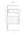
- FIG. 3 illustrates a structural view of an electrode assembly illustrated in FIG. 2 .
- the electrode assembly 60 may be formed by alternately stacked a positive electrode 61, a separator 63, and a negative electrode 62 and then winding them in the form of a jelly roll.
- a positive electrode active material 61a may be coated on the positive electrode 61 and a negative electrode active material 62a may be coated on the negative electrode 62.
- Positive and negative electrode uncoated parts 61b and 62b on which an active material is not coated may be respectively formed on ends of the positive and negative electrodes 61 and 62.
- the positive electrode uncoated part 61b may be disposed at one end of the electrode assembly 60 and the negative electrode uncoated part 62b may be disposed at the other end of the electrode assembly 60, so as to be wound.
- the positive electrode uncoated part 61b is disposed at a left end of the electrode assembly 60 and the negative electrode uncoated part 62b is disposed at a right end of the electrode assembly 60.
- a left current collecting plate 70 illustrated in FIG. 2 may be electrically connected to the positive electrode 61 of the electrode assembly 60 and a right current collecting plate 70 may be electrically connected to the negative electrode 62 of the electrode assembly 60.
- the left and right current collecting plates 70 may be respectively connected to a positive electrode rivet 11 and a negative electrode rivet 12 of a terminal unit.
- the terminal unit includes the positive and negative electrode rivets 11 and 12, rivet terminals 21 and 22 respectively welded to the positive and negative electrode rivets 11 and 12, and bus bars 31 and 32 respectively welded to the rivet terminals 21 and 22 so as to form a serial or parallel connection structure with neighboring, i.e., adjacent, secondary batteries.
- the secondary battery 20 may include another terminal unit, the other terminal unit including another rivet terminal and another electrode rivet.
- the other rivet terminal and the other electrode rivet may be formed of a same metallic material.
- the terminal unit including the multi-metal electrode rivet 12 may have a polarity opposite to a polarity of the other terminal unit including the other electrode rivet.
- the bus bars 30 may include a bus bar 30 coupled to the terminal unit of one of the secondary batteries and to an adjacent secondary battery.
- the bus bar 30 may be formed of the second metallic material.
- the bust bar 30 may be coupled to a terminal of the adjacent secondary battery.
- the positive electrode rivet 11 and the rivet terminals 21 and 22 and the bus bars 31 and 32 are formed of similar metals, e.g., aluminum materials, and the negative electrode rivet 12 are formed of a dissimilar metal, e.g., a copper material.
- welding between the positive electrode rivet 11 and the rivet terminal 21 or between the rivet terminals 21 and 22 and the bus bars 31 and 32 is similar metal welding. Accordingly, the similar metal welding may obtain a sufficient welding strength by using a general welding method and thus may be preformed by using a well-known method.
- the negative electrode rivet 12 may be formed from a dissimilar metal joint material such that similar metal welding may be performed between the negative electrode rivet 12 and the rivet terminal 22.
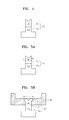
- FIG. 4 illustrates a cross-sectional view of a negative electrode rivet of the secondary battery illustrated in FIG. 2 .
- a head part 12a of the negative electrode rivet 12 which is connected to the current collecting plate 70, may be formed of a copper material
- a tail part 12b of the negative electrode rivet 12, which is connected to the rivet terminal 22 may be formed of an aluminum material as in the rivet terminal 22.
- bonding between the rivet terminal 22 and the negative electrode rivet 12 may also proceed via similar metal welding; and thus a sufficient bonding strength may be obtained by using a laser welding method.
- the negative electrode rivet 12 is formed as described above, dissimilar metal welding may be required and thus a general laser welding method may not provide a sufficient bonding force. Accordingly, in this case, if the head and tail parts 12a and 12b are bonded to each other by using a friction stir welding method, a sufficient bonding strength may be obtained.
- the friction stir welding method may be performed by providing frictional heat to welding portions. Since the friction stir welding method may be performed at a relatively low temperature in comparison to a laser welding method, a heat-affected zone may be small, the welding portions may be uniformly mixed due to friction stirring, and a solid welding strength may be obtained.
- FIG. 5A schematically illustrates an operation of welding the negative electrode rivet 12 by using a friction stir welding method.
- frictional heat may be generated by relatively rotating the head part 12a formed of a copper material and the tail part 12b formed of an aluminum material.
- contact portions of the head and tail parts 12a and 12b may be locally melted and mixed, thereby obtaining a solid welding strength.
- the negative electrode rivet 12 formed as described above may be welded to the rivet terminal 22 as described below.
- FIGS. 5B through 5C illustrate cross-sectional views of stages in a method of bonding a negative electrode rivet and a rivet terminal in the secondary battery module illustrated in FIG. 1 .
- a front end of the tail part 12b of the negative electrode rivet 12 may be rivet-processed so as to closely contact upper portions of the rivet terminal 22.
- the rivet terminal 22 may be locked by the rivet-processed front end of the negative electrode rivet 12 and thus may not be separated away.
- boundaries between the negative electrode rivet 12 and the rivet terminal 22 may be bonded by using, e.g., a laser welding method.
- the welded portions of the negative electrode rivet 12 and the rivet terminal 22 are similar metals, i.e., aluminum materials, and thus a sufficient bonding strength may be obtained by using a laser welding method.
- bonding between the rivet terminals 21 and 22 and the bus bars 31 and 32 may proceed via a similar metal welding method between aluminum materials, and thus may be preformed by using a general laser welding method.
- FIG. 6 illustrates a cross-sectional view of a negative electrode rivet 13 according to another embodiment.
- the negative electrode rivet 13 includes a head part 13a formed of, e.g., a copper material, and a tail part 13b formed of, e.g., an aluminum material.
- the head and tail parts 13a and 13b of the negative electrode rivet 13 are bonded to each other by using a clad metal part 13c instead of a friction stir welding method.
- the clad metal part 13c may be formed by pressure-welding a copper plate formed of a copper material as in the head part 13a and an aluminum plate formed of an aluminum material as in the tail part 13b.
- head and tail parts 13a and 13b are welded to each other by interposing the clad metal part 13c therebetween, similar metal welding may be performed and thus a sufficient bonding strength may be obtained by using a general laser welding method. After that, bonding between the negative electrode rivet 13 and the rivet terminal 22 may be performed as described above in relation to FIGS. 5B and 5C . Accordingly, similar metal welding may be performed between the negative electrode rivet 13 and the rivet terminal 22 and thus a stable bonding strength may be obtained.
- FIG. 7 illustrates a perspective view of a secondary battery module according to another embodiment.
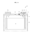
- FIG. 8 illustrates a cross sectional view of a secondary battery of FIG. 7 .
- the terminal unit 22 of one of the secondary batteries 120 may be electrically connected in series or in parallel to the cap assembly 40 of an adjacent secondary battery 120 by using a bus bar 130.
- the cap assembly 40 of the adjacent secondary battery may be electrically connected to one of the electrode plates of the electrode assembly 60 and may serve as a terminal.
- the bus bar 130 may include a thick region 130a and a thin region 130b.
- the thin region 130b may be coupled to the terminal unit 22 of one of the secondary batteries 120 and the thick region 130a may be coupled to the cap assembly 40 of an adjacent secondary battery 120.
- Such a configuration of the bus bar 130 may facilitate accommodation of differences in height between the terminal unit 22 of the one secondary battery 120 and the cap assembly 40 of the adjacent secondary battery 120.
- dissimilar metal welding may occur between a rivet terminal and a positive electrode rivet. Accordingly, regardless of the type of electrode rivet, when dissimilar metal welding is performed between an electrode rivet and a rivet terminal, if the electrode rivet is formed and used as a dissimilar metal joint material, a stable and solid bonding structure may be obtained.
- the embodiments good weldability is achieved and a high bonding strength is obtained.
- the rivet terminals are formed of dissimilar metals corresponding to the metals for forming the positive and negative electrode rivets, weldability between the positive and negative electrode rivets and the rivet terminals is improved, while still avoiding problems associated with dissimilar metal welding between at least one of the rivet terminals and a corresponding bus bar.
- the embodiment may represent a solution for preventing a reduction in weldability, which may be caused when dissimilar metal welding is performed in a terminal unit.
Landscapes
- Chemical & Material Sciences (AREA)
- Chemical Kinetics & Catalysis (AREA)
- Electrochemistry (AREA)
- General Chemical & Material Sciences (AREA)
- Engineering & Computer Science (AREA)
- Manufacturing & Machinery (AREA)
- Inorganic Chemistry (AREA)
- Connection Of Batteries Or Terminals (AREA)
- Battery Mounting, Suspending (AREA)
- Sealing Battery Cases Or Jackets (AREA)
Applications Claiming Priority (2)
| Application Number | Priority Date | Filing Date | Title |
|---|---|---|---|
| US28277210P | 2010-03-30 | 2010-03-30 | |
| US12/926,702 US8673479B2 (en) | 2010-03-30 | 2010-12-06 | Secondary battery and a secondary battery module |
Publications (3)
| Publication Number | Publication Date |
|---|---|
| EP2372814A2 true EP2372814A2 (de) | 2011-10-05 |
| EP2372814A3 EP2372814A3 (de) | 2013-08-07 |
| EP2372814B1 EP2372814B1 (de) | 2015-07-01 |
Family
ID=44246422
Family Applications (1)
| Application Number | Title | Priority Date | Filing Date |
|---|---|---|---|
| EP11158652.5A Active EP2372814B1 (de) | 2010-03-30 | 2011-03-17 | Sekundärbatterie und Sekundärbatteriemodul |
Country Status (4)
| Country | Link |
|---|---|
| US (1) | US8673479B2 (de) |
| EP (1) | EP2372814B1 (de) |
| JP (1) | JP5426594B2 (de) |
| CN (1) | CN102208592B (de) |
Cited By (7)
| Publication number | Priority date | Publication date | Assignee | Title |
|---|---|---|---|---|
| WO2015035023A1 (en) * | 2013-09-06 | 2015-03-12 | Johnson Controls Technology Company | System and method for establishing connections of a battery module |
| EP2887429A1 (de) * | 2013-12-23 | 2015-06-24 | Samsung SDI Co., Ltd. | Sekundärbatterie und Sekundärbatteriemodul |
| EP2899770A1 (de) * | 2014-01-28 | 2015-07-29 | Samsung SDI Co., Ltd. | Anschlußanordnung für eine Sekundärbatterie |
| CN105103337A (zh) * | 2013-07-05 | 2015-11-25 | Lg化学株式会社 | 包括由不同金属组成的连接构件的电池模块 |
| EP2958160B1 (de) * | 2014-06-17 | 2019-05-01 | Samsung SDI Co., Ltd. | Wiederaufladbare batterie |
| WO2020187487A1 (de) | 2019-03-18 | 2020-09-24 | Daimler Ag | Verfahren zur herstellung von elektrischen verbindungen wenigstens zweier batteriezellen für eine batterie eines kraftfahrzeugs, insbesondere eines kraftwagens |
| US11909055B2 (en) | 2018-09-25 | 2024-02-20 | Panasonic Holdings Corporation | Secondary battery |
Families Citing this family (35)
| Publication number | Priority date | Publication date | Assignee | Title |
|---|---|---|---|---|
| KR101165503B1 (ko) * | 2009-09-30 | 2012-07-13 | 삼성에스디아이 주식회사 | 이차 전지 |
| KR101135510B1 (ko) * | 2010-05-20 | 2012-04-13 | 에스비리모티브 주식회사 | 이차 전지 및 전지 모듈 |
| JP5656592B2 (ja) * | 2010-12-06 | 2015-01-21 | 日立オートモティブシステムズ株式会社 | 二次電池 |
| US20130004829A1 (en) * | 2011-07-01 | 2013-01-03 | A123 Systems, Inc. | Heterogeneous Ohmic Contact for a Voltaic Cell |
| WO2013029484A1 (zh) * | 2011-08-29 | 2013-03-07 | 深圳市比亚迪汽车研发有限公司 | 电池端子、电池盖板组件、单体电池和电池组 |
| WO2013065523A1 (ja) * | 2011-10-31 | 2013-05-10 | 三洋電機株式会社 | 組電池及びこの組電池に使用するための角形二次電池 |
| CN103165851B (zh) * | 2011-12-14 | 2016-04-27 | 比亚迪股份有限公司 | 电池端子、电池盖板组件、单体电池和电池组 |
| JP5924522B2 (ja) * | 2012-02-07 | 2016-05-25 | 株式会社Gsユアサ | 蓄電素子、蓄電素子群 |
| JP5970692B2 (ja) * | 2012-03-06 | 2016-08-17 | 日本軽金属株式会社 | 部材の接合方法および貨物運搬用車両の製造方法および貨物運搬用コンテナの製造方法 |
| CN104904036B (zh) * | 2012-12-25 | 2019-05-28 | 株式会社杰士汤浅国际 | 蓄电元件、蓄电元件组件以及蓄电元件的制造方法 |
| KR101689215B1 (ko) * | 2013-01-28 | 2016-12-23 | 삼성에스디아이 주식회사 | 이차전지 |
| JP6133680B2 (ja) * | 2013-05-14 | 2017-05-24 | 日立オートモティブシステムズ株式会社 | 角形二次電池 |
| JP6184747B2 (ja) * | 2013-05-22 | 2017-08-23 | 日立オートモティブシステムズ株式会社 | 角形二次電池 |
| KR101711991B1 (ko) * | 2013-09-16 | 2017-03-03 | 삼성에스디아이 주식회사 | 기둥단자를 갖는 이차 전지 및 이를 이용한 전지 모듈 |
| KR101724013B1 (ko) * | 2013-09-24 | 2017-04-06 | 삼성에스디아이 주식회사 | 결합이 용이한 단자 구조를 가지는 이차전지 |
| EP3062370B1 (de) * | 2013-10-25 | 2019-01-16 | Hitachi Automotive Systems, Ltd. | Rechteckige sekundärbatterie |
| DE102013112060A1 (de) * | 2013-11-01 | 2015-05-07 | Johnson Controls Advanced Power Solutions Gmbh | Elektrochemischer Akkumulator |
| CN104377338B (zh) * | 2013-12-31 | 2016-09-07 | 比亚迪股份有限公司 | 电极端子、具有其的电池盖板组件、电池和电池组 |
| CN106575741A (zh) * | 2014-08-06 | 2017-04-19 | 日立汽车系统株式会社 | 方形二次电池 |
| US10193126B2 (en) | 2014-10-24 | 2019-01-29 | Hitachi Metals, Ltd. | Battery terminal, method for manufacturing battery terminal, and battery |
| CN110165094B (zh) * | 2015-01-12 | 2021-12-28 | 东莞新能安科技有限公司 | 动力电池顶盖 |
| KR102368086B1 (ko) * | 2015-03-16 | 2022-02-24 | 삼성에스디아이 주식회사 | 이차 전지 |
| JP6394908B2 (ja) * | 2015-06-26 | 2018-09-26 | 株式会社豊田自動織機 | 蓄電装置、及び蓄電装置モジュール |
| CN105679991A (zh) * | 2016-03-30 | 2016-06-15 | 湖南方恒复合材料有限公司 | 复合极柱及具有其的电池模块 |
| WO2017181178A1 (en) * | 2016-04-15 | 2017-10-19 | Ems Engineered Material Solutions, Llc | Clad material for electrical terminal connectors and the method of making the same |
| JP6752691B2 (ja) * | 2016-11-18 | 2020-09-09 | ビークルエナジージャパン株式会社 | 二次電池 |
| DE102017210259A1 (de) * | 2017-06-20 | 2018-12-20 | Robert Bosch Gmbh | Batteriezelle |
| US11130197B2 (en) | 2017-11-03 | 2021-09-28 | Greatbatch Ltd. | Laser brazed component and method therefor |
| CN111106299A (zh) | 2018-11-07 | 2020-05-05 | 宁德时代新能源科技股份有限公司 | 二次电池及其制造方法 |
| JP7028825B2 (ja) * | 2019-05-22 | 2022-03-02 | 本田技研工業株式会社 | 組電池 |
| CN114830415A (zh) * | 2020-06-26 | 2022-07-29 | 三星Sdi株式会社 | 可再充电的电池 |
| JP7631718B2 (ja) * | 2020-09-29 | 2025-02-19 | 株式会社Gsユアサ | 蓄電素子 |
| JP7658850B2 (ja) * | 2021-08-18 | 2025-04-08 | トヨタ自動車株式会社 | 組電池およびその製造方法 |
| SE547606C2 (en) * | 2023-01-16 | 2025-10-28 | Northvolt Ab | A covered terminal rivet for a secondary cell and a method of manufacturing a secondary cell |
| WO2024153592A1 (en) * | 2023-01-16 | 2024-07-25 | Northvolt Ab | A covered terminal rivet for a secondary cell and a method of manufacturing a secondary cell |
Family Cites Families (14)
| Publication number | Priority date | Publication date | Assignee | Title |
|---|---|---|---|---|
| GB1367167A (en) | 1971-10-05 | 1974-09-18 | Gates Rubber Co | Electrochemical seal |
| CA2274483C (en) * | 1997-10-07 | 2006-01-31 | Matsushita Electric Industrial Co., Ltd. | Non-aqueous electrolyte secondary battery |
| KR20010017098A (ko) | 1999-08-07 | 2001-03-05 | 김순택 | 각형 밀폐전지 |
| JP2002216716A (ja) | 2000-05-24 | 2002-08-02 | Ngk Insulators Ltd | リチウム二次単電池およびリチウム二次単電池の接続構造体 |
| US6844110B2 (en) * | 2000-05-24 | 2005-01-18 | Ngk Insulators, Ltd. | Lithium secondary cell and assembly thereof |
| JP5173095B2 (ja) | 2001-04-25 | 2013-03-27 | パナソニック株式会社 | 密閉型電池 |
| US7718312B2 (en) | 2002-05-27 | 2010-05-18 | Gs Yuasa Corporation | Battery |
| JP3960877B2 (ja) * | 2002-08-05 | 2007-08-15 | 三洋電機株式会社 | 電池の製造方法 |
| JP4655732B2 (ja) | 2005-04-07 | 2011-03-23 | トヨタ自動車株式会社 | 成形部品の製造方法、成形部品の製造装置、及び、成形部品 |
| KR100922474B1 (ko) * | 2007-01-18 | 2009-10-21 | 삼성에스디아이 주식회사 | 이차 전지 |
| EP2206190A4 (de) | 2007-09-14 | 2012-07-11 | A123 Systems Inc | Wiederaufladbare lithiumzelle mit referenzelektrode zur integritätszustandsüberwachung |
| JP5227752B2 (ja) * | 2007-11-26 | 2013-07-03 | 日立マクセル株式会社 | 密閉型電池、及びこの密閉型電池を用いた電池パックと、この電池パックを搭載した電子機器 |
| US8263255B2 (en) | 2009-10-01 | 2012-09-11 | Sb Limotive Co., Ltd. | Rechargeable battery and battery module |
| US8956753B2 (en) | 2010-03-30 | 2015-02-17 | Samsung Sdi Co., Ltd. | Secondary battery and secondary battery module |
-
2010
- 2010-12-06 US US12/926,702 patent/US8673479B2/en active Active
-
2011
- 2011-03-17 EP EP11158652.5A patent/EP2372814B1/de active Active
- 2011-03-18 JP JP2011060883A patent/JP5426594B2/ja active Active
- 2011-03-30 CN CN201110083696.5A patent/CN102208592B/zh active Active
Non-Patent Citations (1)
| Title |
|---|
| None |
Cited By (11)
| Publication number | Priority date | Publication date | Assignee | Title |
|---|---|---|---|---|
| CN105103337A (zh) * | 2013-07-05 | 2015-11-25 | Lg化学株式会社 | 包括由不同金属组成的连接构件的电池模块 |
| EP2937916A4 (de) * | 2013-07-05 | 2016-08-10 | Lg Chemical Ltd | Batteriemodul mit verbindungselementen aus unterschiedlichen metallen |
| US10069129B2 (en) | 2013-07-05 | 2018-09-04 | Lg Chem, Ltd. | Battery module comprising connecting member composed of dissimilar metals |
| WO2015035023A1 (en) * | 2013-09-06 | 2015-03-12 | Johnson Controls Technology Company | System and method for establishing connections of a battery module |
| US10593925B2 (en) | 2013-09-06 | 2020-03-17 | Cps Technology Holdings Llc | System and method for establishing connections of a battery module |
| EP2887429A1 (de) * | 2013-12-23 | 2015-06-24 | Samsung SDI Co., Ltd. | Sekundärbatterie und Sekundärbatteriemodul |
| US9608252B2 (en) | 2013-12-23 | 2017-03-28 | Samsung Sdi Co., Ltd. | Secondary battery and secondary battery module |
| EP2899770A1 (de) * | 2014-01-28 | 2015-07-29 | Samsung SDI Co., Ltd. | Anschlußanordnung für eine Sekundärbatterie |
| EP2958160B1 (de) * | 2014-06-17 | 2019-05-01 | Samsung SDI Co., Ltd. | Wiederaufladbare batterie |
| US11909055B2 (en) | 2018-09-25 | 2024-02-20 | Panasonic Holdings Corporation | Secondary battery |
| WO2020187487A1 (de) | 2019-03-18 | 2020-09-24 | Daimler Ag | Verfahren zur herstellung von elektrischen verbindungen wenigstens zweier batteriezellen für eine batterie eines kraftfahrzeugs, insbesondere eines kraftwagens |
Also Published As
| Publication number | Publication date |
|---|---|
| EP2372814A3 (de) | 2013-08-07 |
| EP2372814B1 (de) | 2015-07-01 |
| US20110244308A1 (en) | 2011-10-06 |
| JP2011210720A (ja) | 2011-10-20 |
| CN102208592B (zh) | 2015-05-13 |
| JP5426594B2 (ja) | 2014-02-26 |
| CN102208592A (zh) | 2011-10-05 |
| US8673479B2 (en) | 2014-03-18 |
Similar Documents
| Publication | Publication Date | Title |
|---|---|---|
| EP2372814B1 (de) | Sekundärbatterie und Sekundärbatteriemodul | |
| US8956753B2 (en) | Secondary battery and secondary battery module | |
| EP2375474B1 (de) | Sekundärbatterie und Sekundärbatteriemodul | |
| KR101084220B1 (ko) | 이차전지의 단자유닛 및 그 제조방법 | |
| JP7330227B2 (ja) | フレキシブル電池 | |
| KR101217073B1 (ko) | 이차전지 및 이차전지모듈 | |
| US10833372B2 (en) | Rectangular secondary battery | |
| US10411244B2 (en) | Secondary battery and assembled battery | |
| JP7045576B2 (ja) | バッテリーモジュール | |
| US20110287300A1 (en) | Rechargeable battery and battery module | |
| KR102209769B1 (ko) | 배터리 모듈 | |
| US10424809B2 (en) | Secondary battery, method for manufacturing same, and battery pack employing same | |
| EP4243191A2 (de) | Anschlusskomponente und verfahren zur herstellung davon | |
| US20110274964A1 (en) | Battery Tabs and Method of Making the Same | |
| CN113451637A (zh) | 锂离子二次电池 | |
| US11909055B2 (en) | Secondary battery | |
| JP2010086799A (ja) | 積層型電池 | |
| JP7285865B2 (ja) | 端子部品、二次電池および端子部品の製造方法 | |
| US12021267B2 (en) | Battery and method of manufacturing same | |
| WO2023058778A1 (ja) | 電池及び電池の製造方法 | |
| EP4664661A1 (de) | Sekundärbatterie und verfahren zur herstellung einer sekundärbatterie | |
| EP4723318A1 (de) | Kappenanordnung und sekundärbatterie damit | |
| JP2022086352A (ja) | 電池およびその製造方法 | |
| KR20250125568A (ko) | 이차 전지 | |
| JP2022108665A (ja) | 端子部品および二次電池 |
Legal Events
| Date | Code | Title | Description |
|---|---|---|---|
| PUAI | Public reference made under article 153(3) epc to a published international application that has entered the european phase |
Free format text: ORIGINAL CODE: 0009012 |
|
| AK | Designated contracting states |
Kind code of ref document: A2 Designated state(s): AL AT BE BG CH CY CZ DE DK EE ES FI FR GB GR HR HU IE IS IT LI LT LU LV MC MK MT NL NO PL PT RO RS SE SI SK SM TR |
|
| AX | Request for extension of the european patent |
Extension state: BA ME |
|
| 17P | Request for examination filed |
Effective date: 20120326 |
|
| RAP1 | Party data changed (applicant data changed or rights of an application transferred) |
Owner name: ROBERT BOSCH GMBH Owner name: SAMSUNG SDI CO., LTD. |
|
| PUAL | Search report despatched |
Free format text: ORIGINAL CODE: 0009013 |
|
| AK | Designated contracting states |
Kind code of ref document: A3 Designated state(s): AL AT BE BG CH CY CZ DE DK EE ES FI FR GB GR HR HU IE IS IT LI LT LU LV MC MK MT NL NO PL PT RO RS SE SI SK SM TR |
|
| AX | Request for extension of the european patent |
Extension state: BA ME |
|
| RIC1 | Information provided on ipc code assigned before grant |
Ipc: H01M 10/04 20060101ALN20130628BHEP Ipc: H01M 2/30 20060101ALI20130628BHEP Ipc: H01M 2/22 20060101ALI20130628BHEP Ipc: H01M 2/20 20060101AFI20130628BHEP |
|
| GRAP | Despatch of communication of intention to grant a patent |
Free format text: ORIGINAL CODE: EPIDOSNIGR1 |
|
| RIC1 | Information provided on ipc code assigned before grant |
Ipc: H01M 10/04 20060101ALN20150204BHEP Ipc: H01M 2/30 20060101ALI20150204BHEP Ipc: H01M 2/20 20060101AFI20150204BHEP Ipc: H01M 2/22 20060101ALI20150204BHEP |
|
| INTG | Intention to grant announced |
Effective date: 20150309 |
|
| GRAS | Grant fee paid |
Free format text: ORIGINAL CODE: EPIDOSNIGR3 |
|
| GRAA | (expected) grant |
Free format text: ORIGINAL CODE: 0009210 |
|
| AK | Designated contracting states |
Kind code of ref document: B1 Designated state(s): AL AT BE BG CH CY CZ DE DK EE ES FI FR GB GR HR HU IE IS IT LI LT LU LV MC MK MT NL NO PL PT RO RS SE SI SK SM TR |
|
| REG | Reference to a national code |
Ref country code: GB Ref legal event code: FG4D |
|
| REG | Reference to a national code |
Ref country code: AT Ref legal event code: REF Ref document number: 734433 Country of ref document: AT Kind code of ref document: T Effective date: 20150715 Ref country code: CH Ref legal event code: EP |
|
| REG | Reference to a national code |
Ref country code: DE Ref legal event code: R096 Ref document number: 602011017422 Country of ref document: DE |
|
| REG | Reference to a national code |
Ref country code: IE Ref legal event code: FG4D |
|
| REG | Reference to a national code |
Ref country code: AT Ref legal event code: MK05 Ref document number: 734433 Country of ref document: AT Kind code of ref document: T Effective date: 20150701 |
|
| REG | Reference to a national code |
Ref country code: NL Ref legal event code: MP Effective date: 20150701 |
|
| REG | Reference to a national code |
Ref country code: LT Ref legal event code: MG4D |
|
| PG25 | Lapsed in a contracting state [announced via postgrant information from national office to epo] |
Ref country code: NO Free format text: LAPSE BECAUSE OF FAILURE TO SUBMIT A TRANSLATION OF THE DESCRIPTION OR TO PAY THE FEE WITHIN THE PRESCRIBED TIME-LIMIT Effective date: 20151001 Ref country code: LT Free format text: LAPSE BECAUSE OF FAILURE TO SUBMIT A TRANSLATION OF THE DESCRIPTION OR TO PAY THE FEE WITHIN THE PRESCRIBED TIME-LIMIT Effective date: 20150701 Ref country code: LV Free format text: LAPSE BECAUSE OF FAILURE TO SUBMIT A TRANSLATION OF THE DESCRIPTION OR TO PAY THE FEE WITHIN THE PRESCRIBED TIME-LIMIT Effective date: 20150701 Ref country code: GR Free format text: LAPSE BECAUSE OF FAILURE TO SUBMIT A TRANSLATION OF THE DESCRIPTION OR TO PAY THE FEE WITHIN THE PRESCRIBED TIME-LIMIT Effective date: 20151002 Ref country code: FI Free format text: LAPSE BECAUSE OF FAILURE TO SUBMIT A TRANSLATION OF THE DESCRIPTION OR TO PAY THE FEE WITHIN THE PRESCRIBED TIME-LIMIT Effective date: 20150701 |
|
| REG | Reference to a national code |
Ref country code: FR Ref legal event code: PLFP Year of fee payment: 6 |
|
| PG25 | Lapsed in a contracting state [announced via postgrant information from national office to epo] |
Ref country code: RS Free format text: LAPSE BECAUSE OF FAILURE TO SUBMIT A TRANSLATION OF THE DESCRIPTION OR TO PAY THE FEE WITHIN THE PRESCRIBED TIME-LIMIT Effective date: 20150701 Ref country code: PL Free format text: LAPSE BECAUSE OF FAILURE TO SUBMIT A TRANSLATION OF THE DESCRIPTION OR TO PAY THE FEE WITHIN THE PRESCRIBED TIME-LIMIT Effective date: 20150701 Ref country code: HR Free format text: LAPSE BECAUSE OF FAILURE TO SUBMIT A TRANSLATION OF THE DESCRIPTION OR TO PAY THE FEE WITHIN THE PRESCRIBED TIME-LIMIT Effective date: 20150701 Ref country code: AT Free format text: LAPSE BECAUSE OF FAILURE TO SUBMIT A TRANSLATION OF THE DESCRIPTION OR TO PAY THE FEE WITHIN THE PRESCRIBED TIME-LIMIT Effective date: 20150701 Ref country code: SE Free format text: LAPSE BECAUSE OF FAILURE TO SUBMIT A TRANSLATION OF THE DESCRIPTION OR TO PAY THE FEE WITHIN THE PRESCRIBED TIME-LIMIT Effective date: 20150701 Ref country code: IS Free format text: LAPSE BECAUSE OF FAILURE TO SUBMIT A TRANSLATION OF THE DESCRIPTION OR TO PAY THE FEE WITHIN THE PRESCRIBED TIME-LIMIT Effective date: 20151101 Ref country code: ES Free format text: LAPSE BECAUSE OF FAILURE TO SUBMIT A TRANSLATION OF THE DESCRIPTION OR TO PAY THE FEE WITHIN THE PRESCRIBED TIME-LIMIT Effective date: 20150701 Ref country code: PT Free format text: LAPSE BECAUSE OF FAILURE TO SUBMIT A TRANSLATION OF THE DESCRIPTION OR TO PAY THE FEE WITHIN THE PRESCRIBED TIME-LIMIT Effective date: 20151102 |
|
| REG | Reference to a national code |
Ref country code: DE Ref legal event code: R097 Ref document number: 602011017422 Country of ref document: DE |
|
| PG25 | Lapsed in a contracting state [announced via postgrant information from national office to epo] |
Ref country code: DK Free format text: LAPSE BECAUSE OF FAILURE TO SUBMIT A TRANSLATION OF THE DESCRIPTION OR TO PAY THE FEE WITHIN THE PRESCRIBED TIME-LIMIT Effective date: 20150701 Ref country code: EE Free format text: LAPSE BECAUSE OF FAILURE TO SUBMIT A TRANSLATION OF THE DESCRIPTION OR TO PAY THE FEE WITHIN THE PRESCRIBED TIME-LIMIT Effective date: 20150701 Ref country code: CZ Free format text: LAPSE BECAUSE OF FAILURE TO SUBMIT A TRANSLATION OF THE DESCRIPTION OR TO PAY THE FEE WITHIN THE PRESCRIBED TIME-LIMIT Effective date: 20150701 Ref country code: SK Free format text: LAPSE BECAUSE OF FAILURE TO SUBMIT A TRANSLATION OF THE DESCRIPTION OR TO PAY THE FEE WITHIN THE PRESCRIBED TIME-LIMIT Effective date: 20150701 Ref country code: IT Free format text: LAPSE BECAUSE OF FAILURE TO SUBMIT A TRANSLATION OF THE DESCRIPTION OR TO PAY THE FEE WITHIN THE PRESCRIBED TIME-LIMIT Effective date: 20150701 |
|
| PLBE | No opposition filed within time limit |
Free format text: ORIGINAL CODE: 0009261 |
|
| STAA | Information on the status of an ep patent application or granted ep patent |
Free format text: STATUS: NO OPPOSITION FILED WITHIN TIME LIMIT |
|
| PG25 | Lapsed in a contracting state [announced via postgrant information from national office to epo] |
Ref country code: RO Free format text: LAPSE BECAUSE OF FAILURE TO SUBMIT A TRANSLATION OF THE DESCRIPTION OR TO PAY THE FEE WITHIN THE PRESCRIBED TIME-LIMIT Effective date: 20150701 |
|
| 26N | No opposition filed |
Effective date: 20160404 |
|
| PG25 | Lapsed in a contracting state [announced via postgrant information from national office to epo] |
Ref country code: BE Free format text: LAPSE BECAUSE OF NON-PAYMENT OF DUE FEES Effective date: 20160331 Ref country code: SI Free format text: LAPSE BECAUSE OF FAILURE TO SUBMIT A TRANSLATION OF THE DESCRIPTION OR TO PAY THE FEE WITHIN THE PRESCRIBED TIME-LIMIT Effective date: 20150701 |
|
| PG25 | Lapsed in a contracting state [announced via postgrant information from national office to epo] |
Ref country code: LU Free format text: LAPSE BECAUSE OF FAILURE TO SUBMIT A TRANSLATION OF THE DESCRIPTION OR TO PAY THE FEE WITHIN THE PRESCRIBED TIME-LIMIT Effective date: 20160317 Ref country code: MC Free format text: LAPSE BECAUSE OF FAILURE TO SUBMIT A TRANSLATION OF THE DESCRIPTION OR TO PAY THE FEE WITHIN THE PRESCRIBED TIME-LIMIT Effective date: 20150701 |
|
| REG | Reference to a national code |
Ref country code: CH Ref legal event code: PL |
|
| REG | Reference to a national code |
Ref country code: IE Ref legal event code: MM4A |
|
| PG25 | Lapsed in a contracting state [announced via postgrant information from national office to epo] |
Ref country code: BE Free format text: LAPSE BECAUSE OF FAILURE TO SUBMIT A TRANSLATION OF THE DESCRIPTION OR TO PAY THE FEE WITHIN THE PRESCRIBED TIME-LIMIT Effective date: 20150701 |
|
| PG25 | Lapsed in a contracting state [announced via postgrant information from national office to epo] |
Ref country code: LI Free format text: LAPSE BECAUSE OF NON-PAYMENT OF DUE FEES Effective date: 20160331 Ref country code: CH Free format text: LAPSE BECAUSE OF NON-PAYMENT OF DUE FEES Effective date: 20160331 Ref country code: IE Free format text: LAPSE BECAUSE OF NON-PAYMENT OF DUE FEES Effective date: 20160317 |
|
| REG | Reference to a national code |
Ref country code: FR Ref legal event code: PLFP Year of fee payment: 7 |
|
| PG25 | Lapsed in a contracting state [announced via postgrant information from national office to epo] |
Ref country code: NL Free format text: LAPSE BECAUSE OF FAILURE TO SUBMIT A TRANSLATION OF THE DESCRIPTION OR TO PAY THE FEE WITHIN THE PRESCRIBED TIME-LIMIT Effective date: 20150701 |
|
| PG25 | Lapsed in a contracting state [announced via postgrant information from national office to epo] |
Ref country code: MT Free format text: LAPSE BECAUSE OF FAILURE TO SUBMIT A TRANSLATION OF THE DESCRIPTION OR TO PAY THE FEE WITHIN THE PRESCRIBED TIME-LIMIT Effective date: 20150701 |
|
| REG | Reference to a national code |
Ref country code: FR Ref legal event code: PLFP Year of fee payment: 8 |
|
| PG25 | Lapsed in a contracting state [announced via postgrant information from national office to epo] |
Ref country code: HU Free format text: LAPSE BECAUSE OF FAILURE TO SUBMIT A TRANSLATION OF THE DESCRIPTION OR TO PAY THE FEE WITHIN THE PRESCRIBED TIME-LIMIT; INVALID AB INITIO Effective date: 20110317 Ref country code: SM Free format text: LAPSE BECAUSE OF FAILURE TO SUBMIT A TRANSLATION OF THE DESCRIPTION OR TO PAY THE FEE WITHIN THE PRESCRIBED TIME-LIMIT Effective date: 20150701 Ref country code: CY Free format text: LAPSE BECAUSE OF FAILURE TO SUBMIT A TRANSLATION OF THE DESCRIPTION OR TO PAY THE FEE WITHIN THE PRESCRIBED TIME-LIMIT Effective date: 20150701 |
|
| PG25 | Lapsed in a contracting state [announced via postgrant information from national office to epo] |
Ref country code: TR Free format text: LAPSE BECAUSE OF FAILURE TO SUBMIT A TRANSLATION OF THE DESCRIPTION OR TO PAY THE FEE WITHIN THE PRESCRIBED TIME-LIMIT Effective date: 20150701 Ref country code: MT Free format text: LAPSE BECAUSE OF FAILURE TO SUBMIT A TRANSLATION OF THE DESCRIPTION OR TO PAY THE FEE WITHIN THE PRESCRIBED TIME-LIMIT Effective date: 20160331 Ref country code: MK Free format text: LAPSE BECAUSE OF FAILURE TO SUBMIT A TRANSLATION OF THE DESCRIPTION OR TO PAY THE FEE WITHIN THE PRESCRIBED TIME-LIMIT Effective date: 20150701 |
|
| PG25 | Lapsed in a contracting state [announced via postgrant information from national office to epo] |
Ref country code: BG Free format text: LAPSE BECAUSE OF FAILURE TO SUBMIT A TRANSLATION OF THE DESCRIPTION OR TO PAY THE FEE WITHIN THE PRESCRIBED TIME-LIMIT Effective date: 20150701 |
|
| PG25 | Lapsed in a contracting state [announced via postgrant information from national office to epo] |
Ref country code: AL Free format text: LAPSE BECAUSE OF FAILURE TO SUBMIT A TRANSLATION OF THE DESCRIPTION OR TO PAY THE FEE WITHIN THE PRESCRIBED TIME-LIMIT Effective date: 20150701 |
|
| REG | Reference to a national code |
Ref country code: DE Ref legal event code: R079 Ref document number: 602011017422 Country of ref document: DE Free format text: PREVIOUS MAIN CLASS: H01M0002200000 Ipc: H01M0050500000 |
|
| P01 | Opt-out of the competence of the unified patent court (upc) registered |
Effective date: 20230530 |
|
| PGFP | Annual fee paid to national office [announced via postgrant information from national office to epo] |
Ref country code: GB Payment date: 20260303 Year of fee payment: 16 |
|
| PGFP | Annual fee paid to national office [announced via postgrant information from national office to epo] |
Ref country code: DE Payment date: 20260305 Year of fee payment: 16 |
|
| PGFP | Annual fee paid to national office [announced via postgrant information from national office to epo] |
Ref country code: FR Payment date: 20260309 Year of fee payment: 16 |