EP2372839A1 - Hybrides MIMO-Antennenmodul und System der Verwendung davon - Google Patents
Hybrides MIMO-Antennenmodul und System der Verwendung davon Download PDFInfo
- Publication number
- EP2372839A1 EP2372839A1 EP11151522A EP11151522A EP2372839A1 EP 2372839 A1 EP2372839 A1 EP 2372839A1 EP 11151522 A EP11151522 A EP 11151522A EP 11151522 A EP11151522 A EP 11151522A EP 2372839 A1 EP2372839 A1 EP 2372839A1
- Authority
- EP
- European Patent Office
- Prior art keywords
- unit
- loop
- units
- radiating
- antenna module
- Prior art date
- Legal status (The legal status is an assumption and is not a legal conclusion. Google has not performed a legal analysis and makes no representation as to the accuracy of the status listed.)
- Granted
Links
Images




Classifications
-
- H—ELECTRICITY
- H01—ELECTRIC ELEMENTS
- H01Q—ANTENNAS, i.e. RADIO AERIALS
- H01Q21/00—Antenna arrays or systems
- H01Q21/28—Combinations of substantially independent non-interacting antenna units or systems
-
- H—ELECTRICITY
- H01—ELECTRIC ELEMENTS
- H01Q—ANTENNAS, i.e. RADIO AERIALS
- H01Q21/00—Antenna arrays or systems
- H01Q21/06—Arrays of individually energised antenna units similarly polarised and spaced apart
- H01Q21/20—Arrays of individually energised antenna units similarly polarised and spaced apart the units being spaced along or adjacent to a curvilinear path
- H01Q21/205—Arrays of individually energised antenna units similarly polarised and spaced apart the units being spaced along or adjacent to a curvilinear path providing an omnidirectional coverage
-
- H—ELECTRICITY
- H01—ELECTRIC ELEMENTS
- H01Q—ANTENNAS, i.e. RADIO AERIALS
- H01Q21/00—Antenna arrays or systems
- H01Q21/30—Combinations of separate antenna units operating in different wavebands and connected to a common feeder system
-
- H—ELECTRICITY
- H01—ELECTRIC ELEMENTS
- H01Q—ANTENNAS, i.e. RADIO AERIALS
- H01Q7/00—Loop antennas with a substantially uniform current distribution around the loop and having a directional radiation pattern in a plane perpendicular to the plane of the loop
-
- H—ELECTRICITY
- H01—ELECTRIC ELEMENTS
- H01Q—ANTENNAS, i.e. RADIO AERIALS
- H01Q9/00—Electrically-short antennas having dimensions not more than twice the operating wavelength and consisting of conductive active radiating elements
- H01Q9/04—Resonant antennas
- H01Q9/0407—Substantially flat resonant element parallel to ground plane, e.g. patch antenna
- H01Q9/0421—Substantially flat resonant element parallel to ground plane, e.g. patch antenna with a shorting wall or a shorting pin at one end of the element
Definitions
- the present invention relates to a multiple-input multiple-output antenna module, and more particularly, to a hybrid multiple-input multiple-output antenna module and a system of using the same.
- the wireless LAN or 802.11a/b/g/n access-point antenna of the related art is almost of an external antenna structure.
- Common dipole antennas have a plastic or rubber sleeve covering thereon.
- the dipole antenna is a single-band antenna for 2.4 GHz operation or a dual-band single-radio antenna for 2.4/5 GHz operation.
- the height of the dipole antenna is triple the thickness of the wireless broadband router/hub device, and one part of the dipole antenna is arranged on a side of the router and the rest of the dipole antenna is protruding from the top of the access-point or router enclosure.
- the protruded part of the dipole antenna can easily be vandalized by an outside force and also occupies space, which deteriorates the aesthetic appeal of the product, especially for the multi-antenna system.
- the related art provides another dual-band cross polarization dipole antenna that discloses a dual-antenna system.
- the dual-antenna system has two dual-band dipole antennas to generate two frequency bands for 2.4/5 GHz operation.
- the dual-antenna structure is of a stacked structure, thus the height of the whole antenna structure is high.
- the enterprise access-point antenna or the router is usually installed on a ceiling.
- the downlink and uplink qualities would be directly affected by the antennas radiation-pattern coverage.
- the path loss of a 5 GHz antenna is larger than the path loss of a 2.4 GHz antenna. Therefore, the gain of a 5 GHz antenna needs to be larger in order to compensate high path loss in 5 GHz band.
- One particular aspect of the present invention is to provide a hybrid multiple-input multiple-output antenna module and a system of using the same.
- the present invention not only has some advantages such as small size, low profile, good isolation, high antenna gain and good radiation properties, but also can replace the external dual-band access-point antennas of the prior art for 2.4/5 GHz operation with no need of extra diplexers.
- the hybrid multiple-input multiple-output antenna module can be hidden in the wireless communication device in order to enhance the appearance of the product.
- the present invention provides a hybrid multiple-input multiple-output antenna module, including: a grounding unit, a plurality of radiating units, loop units and filter units.
- the radiating units are mounted on the grounding unit.
- the loop units are arranged along the outer peripheral side of the grounding unit and vertically arranged on the grounding unit.
- the filter units are arranged on the grounding unit and respectively electrically connected to the second feeding pins of the loop units.
- the radiating units and the loop units are arranged around a geometric center of the grounding unit and are alternately and symmetrically arranged on the grounding unit.
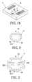
- FIG. 1A is a top, schematic view of the first embodiment of the present invention
- FIG. 1B is a perspective, schematic view of the first embodiment of the present invention.
- FIG. 1C is a perspective, schematic view of one radiating unit according to the first embodiment of the present invention.
- FIG. 1D is a front, schematic view of one loop unit according to the first embodiment of the present invention.
- FIG. 1E is a curve diagram of the reflection coefficients (S parameters (dB)) of the first radiating unit against frequencies (MHz) according to the first embodiment of the present invention
- FIG. 1F is a curve diagram of the reflection coefficients of the third loop unit against frequencies according to the first embodiment of the present invention.
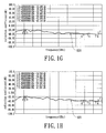
- FIG. 1G is a curve diagram of the isolation between the second radiating unit and the first radiating unit against frequencies according to the present invention
- FIG. 1H is a curve diagram of the isolation between the third radiating unit and the first radiating unit against frequencies according to the present invention.
- FIG. 1I is a curve diagram of the isolation between the first loop unit and the first radiating unit against frequencies according to the present invention
- FIG. 1 is a curve diagram of the isolation between the second loop unit and the first radiating unit against frequencies according to the present invention
- FIG. 1K is a curve diagram of the isolation between the third loop unit and the first radiating unit against frequencies according to the present invention
- FIG. 1L is a curve diagram of the isolation between the second loop unit and the first loop unit against frequencies according to the present invention
- FIG. 1M is a curve diagram of the isolation between the third loop unit and the first loop unit against frequencies according to the present invention
- FIG. 1N is a perspective, schematic view of the hybrid multiple-input multiple-output antenna module installed in a wireless device housing according to the first embodiment of the present invention
- FIG. 2 is a front, schematic view of one loop unit according to the second embodiment of the present invention.
- FIG. 3 is a front, schematic view of one loop unit according to the third embodiment of the present invention.
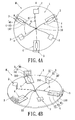
- FIG. 4A is a top, schematic view of the fourth embodiment of the present invention.
- FIG. 4B is a perspective, schematic view of the fourth embodiment of the present invention.
- the first embodiment of the present invention provides a hybrid multiple-input multiple-output antenna module M, including: a grounding unit 1, a plurality of radiating units 2, a plurality of loop units 3 and a plurality of filter units 4.
- the grounding unit 1 and the loop units 3 may be integrally combined to form a one-piece plate structure.
- the loop units 3 may be manufactured respectively, and then the finished loop units 3 are arranged along the outer peripheral side of the finished grounding unit 1.
- the radiating units 2 and the loop units 3 are arranged around a geometric center of the grounding unit 1, and the radiating units 2 and the loop units 3 are alternately and symmetrically arranged on the grounding unit 1.
- Each radiating unit 2 has a geometric centerline A (the geometric centerline A connects to the geometric center of the grounding unit 1) and each loop unit 3 has a geometric centerline B (the geometric centerline B connects to the geometric center of the grounding unit 1), and every two adjacent geometric centerlines (A, B) and the loop unit 3 intersect at the geometric center of the grounding unit 1 to form an included angle ⁇ and each of the included angles ⁇ has substantially the same measure.
- two geometric centerlines A of every two adjacent radiating units 2 (or every two adjacent loop units 3) intersect at the geometric center of the grounding unit 1 to form an included angle ⁇ ' and each of the included angles ⁇ ' has substantially the same measure.
- each included angle ⁇ is 60 degrees and each included angle ⁇ ' is 120 degrees (as shown in FIG. 1A ).
- the grounding unit 1 may be a regular polygonal conductive plate, a circular conductive plate or any conductive plates with a predetermined shape.
- the first embodiment shows the regular polygonal conductive plate as an example, and the grounding unit 1 has a through hole 10 passing through a central portion thereof.
- the hybrid multiple-input multiple-output antenna module M further includes a plurality of signal transmission lines 5. One end of the each signal transmission line 5 is electrically connected to the radiating unit 2 or the loop unit 3, and another end of the signal transmission line 5 passes through the through hole 10, thus the signal transmission lines 5 may be routed neatly by passing through the through hole 10.
- antenna signals received by the radiating units 2 or the loop units 3 may be transmitted to wireless device system PCB (not shown) of a router by using the signal transmission lines 5.
- wireless device system PCB not shown
- the present invention can omit the through hole 10, thus the signal transmission lines 5 may be attached to the top surface of the grounding unit 1 in order to facilitate the cable routing for the signal transmission lines 5.
- the radiating units 2 are arranged on the grounding unit 1 and are separated from the outer peripheral sides 100 of the grounding unit 1 by a predetermined distance.
- Each radiating unit 2 has a first radiating body 22 parallel to the surface of the grounding unit 1 and extended towards outer peripheral side 100 of the grounding unit 1, at least one first feeding pin 21 having a first feeding point 210 on a bottom portion thereof being extended downwards from one side of the first radiating body 22 and being suspended above the grounding unit 1 at a predetermined distance, and at least one first shorting pin 20 being extended downwards from one side of the first radiating body 22 and being connected to the grounding unit 1.
- both the first feeding pin 21 and the first shorting pin 20 are coplanar, and both the first feeding pin 21 and the first shorting pin 20 and the radiating body 22 are non-coplanar.
- each loop unit 3 has at least one second shorting pin 30 mounted on the grounding unit 1, at least one second feeding pin 31 having a second feeding point 310 on a bottom portion thereof separated from the second shorting pin 30 by a predetermined distance and suspended above the grounding unit 1 at a predetermined distance, and at least one second radiating body 32 vertically suspended above the grounding unit 1 at a predetermined distance and connected between the second shorting pin 30 and the second feeding pin 31.
- the second shorting pin 30 and the second feeding pin 31 of each loop unit 3 are symmetrically arranged beside two sides (left direction and right direction) of the geometric centerline B of each loop unit 3.
- the second radiating body 32, the second feeding pin 31 and the second shorting pin 30 are coplanar.
- the filter units 4 are arranged on the grounding unit 1 and parallelly attached to the surface of the grounding unit 1, and the filter units 4 are respectively electrically connected to the second feeding pins 31 of the loop units 3 for filtering particular transmission signal.
- Each filter unit 4 has a first transmission section 41, a second transmission section 42 and a microwave printed filter 43 connected between the first transmission section 41 and the second transmission section 42.
- One end of the first transmission section 41 of each filter unit 4 is electrically connected to the second feeding pin 31 of each loop unit 3 and one end of the second transmission section 42 of each filter unit 4 is electrically connected to a signal transmission line 5.
- Each filter unit 4 may be a band-stop filter for restraining half-wavelength resonant mode of each loop unit 3, in which the half-wavelength resonant mode of each loop unit 3 is close to the antenna operating frequencies of each radiating unit 2.
- the antenna operating frequencies of each radiating unit 2 may be 2.4 GHz
- the antenna operating frequencies of each loop unit 3 may be 5 GHz
- each filter unit 4 may be a 2.4 GHz printed microstrip band-stop filter electrically connected to a second feeding point 310 of each loop unit 3 (such as a 5 GHz loop antenna) for restraining half-wavelength resonant mode of 5 GHz loop antenna, in which the half-wavelength resonant mode of 5 GHz loop antenna is close to 2.4 GHz operating frequencies band. Therefore, the isolation for 2.4 GHz operation between 2.4 GHz antenna and 5 GHz antenna would be decreased because the two antennas do not have the overlapped operating frequencies of the nearby resonant modes.
- the radiating units 2 and the loop units 3 have some different design aspects according to different design requirements, as follows:
- the first feeding pin 21 is adjacent to the second shorting pin 30 that is arranged beside the left side
- the first shorting pin 20 is adjacent to the second feeding pin 31 that is arranged beside the right side.
- the above-mentioned alternate-antenna design can prevent the first feeding pins 21 and the second feeding pins 31 from being coupled with each other and prevent the first shorting pins 20 and the second shorting pins 30 from being coupled with each other. Therefore, the mutual coupling between each radiating unit 2 with first antenna operating frequencies (first frequency band) and each loop unit 3 with second antenna operating frequencies (second frequency band) is substantially decreased and the isolation can be remained under at least -20 dB.
- the first shorting pin 20 and the first feeding pin 21 of each radiating unit 2 are separated from each other by a predetermined distance
- the second shorting pin 30 and the second feeding pin 31 of each loop unit 3 are separated from each other by a predetermined distance, in order to obtain good impedance matching.
- a designer can adjust the above-mentioned predetermined distances in order to change antenna operating frequencies according to different design requirements.
- the heights of each radiating unit 2 and each loop unit 3 relative to the grounding unit 1 also may be adjusted according to different antenna performance (such as antenna radiation patterns and antenna gain) that a designer wants.
- the hybrid multiple-input multiple-output antenna module M can obtain good impedance matching (defined by 2:1 VSWR or 10dB return loss) for WLAN operation in the 2.4/5 GHz bands by adjusting (1) the distance between the first shorting pin 20 and the first feeding pin 21 of each radiating unit 2, (2) the distance between the second shorting pin 30 and the second feeding pin 31 of each loop unit 3, and (3) the height of each radiating unit 2 and the height of each loop unit 3 relative to the grounding unit 1.
- impedance matching defined by 2:1 VSWR or 10dB return loss
- the first feeding points 210 and the second feeding points 310 face the geometric center of the grounding unit 1.
- the distance between each first feeding point 210 and the geometric center of the grounding unit 1 may be different from the distance between each second feeding point 310 and the geometric center of the grounding unit 1, but the distance between any one of feeding points with the same operating frequencies or the loop unit 3 and the geometric center of the grounding unit 1 is the same.
- the signal transmission lines 5 are respectively connected to the first feeding points 210 of the first feeding pins 21 and the second feeding points 310 of the second feeding pins 31 through the filter units 4.
- antenna signals received by the radiating units 2 or the loop units 3 may be transmitted to wireless device system PCB of a router by using the signal transmission lines 5.
- the first shorting pin 20 and the first feeding pin 21 of each radiating unit 2 are formed on the same plane and both the first shorting pin 20 and the first feeding pin 21 are approximately vertical to the first radiating body 22.
- the second shorting pin 30, the second feeding pin 31 and the second radiating body 32 of each loop unit 3 are formed on the same plane or curved surface.
- the antenna operating frequencies of the radiating units 2 are the same (such as antenna lower frequency band), and the antenna operating frequencies of the loop units 3 are the same (such as antenna higher frequency band).
- the antenna operating frequencies of each radiating unit 2 may be in 2.4 GHz band, and the antenna operating frequencies of each loop unit 3 may be in 5 GHz band.
- FIG. 1A shows three radiating units 2, the topmost one of the three radiating units 2 is defined as a first one (label S1) of the three radiating units 2, another radiating unit 2 arranged at the lower left-hand corner is defined as a second one (label S2) of the three radiating units 2, and the other radiating unit 2 arranged at the lower right-hand corner is defined as a third one (label S3) of the three radiating units 2.
- label S1 label S1
- label S2 another radiating unit 2 arranged at the lower left-hand corner
- label S3 the other radiating unit 2 arranged at the lower right-hand corner
- 1A shows three loop units 3, one loop unit 3 arranged at the upper right-hand corner is defined as a first one (label S4) of the three loop units 3, another loop unit 3 arranged at the upper left-hand corner is defined as a second one (label S5) of the three loop units 3, and the bottommost one of the three loop units 3 is defined as a third one (label S6) of the three loop units 3.
- FIG. 1E shows reflection coefficients (S parameters (dB)) of the radiating units 2 such as the curve in FIG. 1E ) against frequencies (MHz) according to the test results of the radiating units 2.
- S parameters (dB) reflection coefficients of the radiating units 2 such as the curve in FIG. 1E
- frequencies (MHz) according to the test results of the radiating units 2.
- the reflection coefficients in 2.4 GHz band are below -10 dB.
- FIG 1F shows reflection coefficients (S parameters (dB)) of the loop units 3 such as the curve in FIG. 1F ) against frequencies (MHz) according to the test results of the loop units 3.
- the reflection coefficients in 5 GHz band are below -7.3 dB according to the four frequency points (1, 2, 3 and 4) labeled in FIG. 1F .
- FIGS. 1G to 1M respectively show the isolation (S parameters (dB)) between any two of the radiating units 2 and the loop units 3 against frequencies (MHz) according to the test results of the radiating units 2 and the loop units 3.
- the radiating units 2 and the loop units 3 are labeled from S1 to S6.
- S21 means the isolation between second one and first one of the radiating units 2.
- S31 means the isolation between third one and first one of the radiating units 2.
- S41 means the isolation between first one of the loop units 3 and first one of the radiating units 2.
- S51 means the isolation between second one of the loop units 3 and first one of the radiating units 2.
- S61 means the isolation between third one of the loop units 3 and first one of the radiating units 2.
- S54 means the isolation between second one and first one of the loop units 3.
- S64 means the isolation between third one and first one of the loop units 3.
- the isolation in 2.4 GHz and 5 GHz bands can be remained under at least -20 dB as shown in FIGS. 1G to 1M .
- the isolation in 2.4 GHz band can be remained under at least -45 dB due to the usage of the filter units 4 that can restrain the half-wavelength resonant mode of each loop unit 3.
- the hybrid multiple-input multiple-output antenna module M may be installed in a wireless device housing C that is applied to a wireless communication device (such as router or hub) in order to form a system of the hybrid multiple-input multiple-output antenna module.
- the hybrid multiple-input multiple-output antenna module M may be installed on the internal side of a top cover of the wireless device housing C.
- the grounding unit 1, the radiating units 2, the loop units 3 and the filter units 4 are enclosed by the wireless device housing C.
- the hybrid multiple-input multiple-output antenna module M may be hidden in the wireless communication device without need to be placed outside the wireless device housing C in order to enhance the appearance of the wireless communication device that uses hybrid multiple-input multiple-output antenna module M.
- the second embodiment of the present invention provides a hybrid multiple-input multiple-output antenna module M, including: a grounding unit 1, a plurality of radiating units 2, a plurality of loop units 3 and a plurality of filter units 4.
- the difference between the second embodiment and the first embodiment is that: in the second embodiment, the second radiating body 32 of each loop unit 3 is an arc-shaped body connected between each corresponding second shorting pin 30 and each corresponding second feeding pin 31.
- the third embodiment of the present invention provides a hybrid multiple-input multiple-output antenna module M, including: a grounding unit 1, a plurality of radiating units 2, a plurality of loop units 3 and a plurality of filter units 4.
- the second radiating body 32 of each loop unit 3 has two symmetrical curved portions 320.
- the two curved portions 320 are symmetric with respect to the geometric centerline B of each loop unit 3.
- the resonant path is also increased in order to decrease antenna operating frequencies and size of the hybrid multiple-input multiple-output antenna module M.
- the fourth embodiment of the present invention provides a hybrid multiple-input multiple-output antenna module M, including: a grounding unit 1, a plurality of radiating units 2, a plurality of loop units 3 and a plurality of filter units 4.
- the difference between the fourth embodiment and the first embodiment is that: in the fourth embodiment, the second shorting pin 30, the second feeding pin 31 and the second radiating body 32 of each loop unit 3 are formed on the same curved surface and substantially vertical to the grounding unit 1.
- the width of each second radiating body 32 is increased in the fourth embodiment in order to increase resonant path without enlarging the size of the hybrid multiple-input multiple-output antenna module M.
- the present invention has some advantages according to the above-mentioned examples, as follows:
- Each radiating unit may be a shorted monopole antenna and each loop unit may be a loop antenna, and thus the present invention can combine different antenna types and different antenna radiation patterns to form the hybrid multiple-input multiple-output antenna module.
- the present invention uses three independent radiating units (such as three independent short-circuited monopole antennas) for 2.4 GHz operation and three independent loop units (such as three independent loop antennas) for 5 GHz operation in order to achieve concurrent dual-band operation.
- the present invention is different from the dual-band single-radio antenna of the related art.
- the dual-band single-radio antenna of the related art has one RF signal feeding port only, thus the dual-band single-radio antenna of the related art needs to use an extra diplexer to achieve concurrent dual-band operation. Therefore, for the dual-band single-radio antenna of the related art, the cost would be increased and the whole system loses extra gain or power.
- the whole height of the hybrid multiple-input multiple-output antenna module does not exceed 15 mm in order to achieve the purpose of manufacturing built-in multi-antenna system.
- the built-in hybrid multiple-input multiple-output antenna module may be hidden in the access point or router in order to enhance the appearance of the wireless communication device.
- the hybrid multiple-input multiple-output antenna module can obtain good impedance matching (defined by 2:1 VSWR or 10dB return loss) for WLAN operation in 2.4 GHz and 5 GHz bands by adjusting (1) the distance between the first shorting pin and the first feeding pin of each radiating unit, (2) the distance between the second shorting pin and the second feeding pin of each loop unit, and (3) the height of each radiating unit and the height of each loop unit relative to the grounding unit.
- the mutual coupling between each radiating unit and each loop unit is substantially decreased and the isolation can be remained under at least -20 dB.
- Each radiating unit such as a shorted monopole antenna for 2.4 GHz operation can provides inverted conical radiation patterns for the design of access-point antennas applied to the ceiling, and each loop unit may be of a one-wavelength loop structure that is a balanced structure that can substantially mitigate the surface currents excited on the surface of the antenna ground plane or system ground plane. Therefore, the ground plane such as the grounding unit may act as a reflector, thus the directivity of the antenna radiation is large to obtain high antenna gain for compensating high path loss at 5 GHz operating band and to increase communications coverage.
- the loop units are vertically arranged on the edge (such as the outer peripheral sides) of the grounding unit. Because the antenna radiation patterns are reflected by the grounding unit along two orthogonal directions (one direction is vertical to the grounding unit and horizontal to the radiating units and the loop units, and the other direction is horizontal to the grounding unit), 3-dB half-power beamwidth of each loop unit in the elevation planes can cover wide angle that is more than at least one quadrant on the polar coordinate. Hence, each loop unit has a wide beamwidth radiating patterns.
- the grounding unit and the loop units may be made of one-piece metal plate by stamping or cutting. Hence, the present invention can effectively decrease manufacturing cost and time.
- Each filter unit is a 2.4 GHz printed microstrip band-stop filter electrically connected to the second feeding point of each loop unit (such as a 5 GHz loop antenna) for restraining half-wavelength resonant mode of 5 GHz loop antenna, in which the half-wavelength resonant mode of 5 GHz loop antenna is close to 2.4 GHz operating frequency band. Therefore, the isolation at 2.4 GHz operation between 2.4 GHz antenna and 5 GHz antenna would be decreased because the two antennas do not have the overlapped operating frequencies of the nearby resonant modes.
Landscapes
- Variable-Direction Aerials And Aerial Arrays (AREA)
- Waveguide Aerials (AREA)
Applications Claiming Priority (1)
| Application Number | Priority Date | Filing Date | Title |
|---|---|---|---|
| CN2010201767408U CN201655979U (zh) | 2010-04-02 | 2010-04-02 | 复合式多输入多输出天线模块及其系统 |
Publications (2)
| Publication Number | Publication Date |
|---|---|
| EP2372839A1 true EP2372839A1 (de) | 2011-10-05 |
| EP2372839B1 EP2372839B1 (de) | 2014-04-23 |
Family
ID=43121221
Family Applications (1)
| Application Number | Title | Priority Date | Filing Date |
|---|---|---|---|
| EP11151522.7A Active EP2372839B1 (de) | 2010-04-02 | 2011-01-20 | Hybrides MIMO-Antennenmodul und System der Verwendung davon |
Country Status (4)
| Country | Link |
|---|---|
| US (1) | US8482471B2 (de) |
| EP (1) | EP2372839B1 (de) |
| CN (1) | CN201655979U (de) |
| ES (1) | ES2460640T3 (de) |
Cited By (6)
| Publication number | Priority date | Publication date | Assignee | Title |
|---|---|---|---|---|
| EP2752942A1 (de) * | 2013-01-07 | 2014-07-09 | Arcadyan Technology Corp. | Rundstrahlantenne |
| WO2016127875A1 (zh) * | 2015-02-15 | 2016-08-18 | 上海贝尔股份有限公司 | 用于无线通信系统的天线反射板结构及天线 |
| US9509060B2 (en) | 2014-08-19 | 2016-11-29 | Symbol Technologies, Llc | Open waveguide beamforming antenna for radio frequency identification reader |
| CN107369898A (zh) * | 2017-07-07 | 2017-11-21 | 深圳前海科蓝通信有限公司 | 一种窄波束扫描智能mimo天线 |
| US9847571B2 (en) | 2013-11-06 | 2017-12-19 | Symbol Technologies, Llc | Compact, multi-port, MIMO antenna with high port isolation and low pattern correlation and method of making same |
| US10158178B2 (en) | 2013-11-06 | 2018-12-18 | Symbol Technologies, Llc | Low profile, antenna array for an RFID reader and method of making same |
Families Citing this family (40)
| Publication number | Priority date | Publication date | Assignee | Title |
|---|---|---|---|---|
| US8854266B2 (en) | 2011-08-23 | 2014-10-07 | Apple Inc. | Antenna isolation elements |
| CN103096524B (zh) * | 2011-10-31 | 2018-09-21 | 深圳光启高等理工研究院 | 基于柔性电路板的无线路由器 |
| CN103247867A (zh) * | 2012-02-14 | 2013-08-14 | 启碁科技股份有限公司 | 射频装置、无线通讯装置及提升天线隔离度的方法 |
| CN103298165B (zh) * | 2012-02-29 | 2018-04-17 | 深圳光启创新技术有限公司 | 一种路由器 |
| CN103297345B (zh) * | 2012-02-29 | 2018-09-14 | 深圳光启创新技术有限公司 | 一种路由器 |
| CN103369412B (zh) * | 2012-04-01 | 2018-10-23 | 深圳光启创新技术有限公司 | 一种路由器 |
| US9203139B2 (en) | 2012-05-04 | 2015-12-01 | Apple Inc. | Antenna structures having slot-based parasitic elements |
| US9407004B2 (en) * | 2012-07-25 | 2016-08-02 | Tyco Electronics Corporation | Multi-element omni-directional antenna |
| WO2014027875A1 (en) | 2012-08-17 | 2014-02-20 | Laird Technologies, Inc. | Multiband antenna assemblies |
| CN102916245A (zh) * | 2012-11-17 | 2013-02-06 | 福建邮科通信技术有限公司 | 一种终端宽频全向mimo天线 |
| USD733104S1 (en) * | 2013-01-18 | 2015-06-30 | Airgain, Inc. | Maximum beam antenna |
| EP2962362B1 (de) * | 2013-03-01 | 2020-05-06 | Honeywell International Inc. | Zirkulär polarisierte antenne |
| CN104253310B (zh) * | 2013-06-28 | 2018-06-26 | 华为技术有限公司 | 多天线系统及移动终端 |
| US9985363B2 (en) * | 2013-10-18 | 2018-05-29 | Venti Group, LLC | Electrical connectors with low passive intermodulation |
| TWI536660B (zh) | 2014-04-23 | 2016-06-01 | 財團法人工業技術研究院 | 通訊裝置及其多天線系統設計之方法 |
| CN105337050A (zh) * | 2014-06-12 | 2016-02-17 | 索尼公司 | 天线结构、通信装置以及电子设备 |
| US9735822B1 (en) * | 2014-09-16 | 2017-08-15 | Amazon Technologies, Inc. | Low specific absorption rate dual-band antenna structure |
| USD798846S1 (en) * | 2014-11-17 | 2017-10-03 | Airgain Incorporated | Antenna assembly |
| USD804458S1 (en) * | 2014-12-31 | 2017-12-05 | Airgain Incorporated | Antenna |
| USD804457S1 (en) * | 2014-12-31 | 2017-12-05 | Airgain Incorporated | Antenna assembly |
| US9812791B2 (en) * | 2015-03-11 | 2017-11-07 | Aerohive Networks, Inc. | Single band dual concurrent network device |
| CN107534213B (zh) | 2015-03-11 | 2020-10-20 | 极进网络公司 | 单频带双重并行网络装置 |
| TWI571004B (zh) * | 2015-03-13 | 2017-02-11 | 綠億科技股份有限公司 | 天線模組及其天線結構 |
| DE102015211420A1 (de) * | 2015-06-22 | 2016-12-22 | Continental Automotive Gmbh | Spulenanordnung insbesondere für ein Fahrzeug-Zugangs-und/oder-Fahrzeug-Start-und/oder-Schlüssel-Positionsbestimmungs-System |
| USD813851S1 (en) * | 2015-07-30 | 2018-03-27 | Airgain Incorporated | Antenna |
| USD823284S1 (en) | 2015-09-02 | 2018-07-17 | Aerohive Networks, Inc. | Polarized antenna |
| CN105704050B (zh) * | 2016-03-25 | 2019-01-25 | 北京禹宸隆科技有限公司 | 智能路由器 |
| TWI629835B (zh) | 2016-07-21 | 2018-07-11 | 和碩聯合科技股份有限公司 | 天線單元、天線系統及天線控制方法 |
| USD820817S1 (en) * | 2017-03-06 | 2018-06-19 | Fitivision Technology Inc. | Antenna used in wireless communication |
| US11362698B2 (en) * | 2017-07-20 | 2022-06-14 | L3Harris Technologies, Inc. | Low-insertion-loss triple throw switch |
| CN108232471B (zh) * | 2017-12-29 | 2021-01-08 | 四川九洲电器集团有限责任公司 | 一种四向天线 |
| CN207868388U (zh) | 2018-02-13 | 2018-09-14 | 中磊电子(苏州)有限公司 | 天线系统 |
| CN110797634B (zh) * | 2018-08-03 | 2022-04-05 | 荣耀终端有限公司 | 一种天线结构件及电子设备 |
| TWI731269B (zh) * | 2018-10-02 | 2021-06-21 | 緯創資通股份有限公司 | 天線系統 |
| EP3713012A1 (de) * | 2019-03-22 | 2020-09-23 | The Antenna Company International N.V. | Mimo-antennensystem, drahtlose vorrichtung und drahtloses kommunikationssystem |
| NL2022792B1 (en) * | 2019-03-22 | 2020-09-28 | The Antenna Company International N V | MIMO antenna system, wireless device, and wireless communication system |
| TWI700862B (zh) * | 2019-10-23 | 2020-08-01 | 華碩電腦股份有限公司 | 迴圈式雙天線系統 |
| CN114335993B (zh) * | 2021-12-17 | 2025-04-22 | 苏州硕贝德通讯技术有限公司 | 一种一体式钣金成型的路由器内置天线 |
| USD1011326S1 (en) * | 2022-02-02 | 2024-01-16 | Jayshri Sharad Kulkarni | MIMO antenna |
| USD1010628S1 (en) * | 2022-02-02 | 2024-01-09 | Jayshri Sharad Kulkarni | Four-port MIMO antenna with whirligig isolating structure |
Citations (4)
| Publication number | Priority date | Publication date | Assignee | Title |
|---|---|---|---|---|
| US6140972A (en) * | 1998-12-11 | 2000-10-31 | Telecommunications Research Laboratories | Multiport antenna |
| US20030210193A1 (en) * | 2002-05-13 | 2003-11-13 | Rossman Court Emerson | Low Profile Two-Antenna Assembly Having a Ring Antenna and a Concentrically-Located Monopole Antenna |
| US7450082B1 (en) * | 2006-03-31 | 2008-11-11 | Bae Systems Information And Electronics Systems Integration Inc. | Small tuned-element GPS antennas for anti-jam adaptive processing |
| US20090009401A1 (en) * | 2007-07-04 | 2009-01-08 | Kabushiki Kaisha Toshiba | Antenna device having no less than two antenna elements |
Family Cites Families (8)
| Publication number | Priority date | Publication date | Assignee | Title |
|---|---|---|---|---|
| NO316658B1 (no) * | 2002-11-05 | 2004-03-22 | 3D Radar As | Antennesystem for en georadar |
| US6819291B1 (en) * | 2003-06-02 | 2004-11-16 | Raymond J. Lackey | Reduced-size GPS antennas for anti-jam adaptive processing |
| CA2562479A1 (en) * | 2004-04-12 | 2005-12-01 | Airgain, Inc. | Switched multi-beam antenna |
| US7427955B2 (en) * | 2004-12-08 | 2008-09-23 | Electronics And Telecommunications Research Institute | Dual polarization antenna and RFID reader employing the same |
| FR2915025B1 (fr) * | 2007-04-13 | 2014-02-14 | Centre Nat Etd Spatiales | Antenne a elements rayonnants inclines |
| CN101971420B (zh) * | 2008-02-04 | 2013-12-04 | 联邦科学和工业研究机构 | 圆形极化的阵列天线 |
| CN101895017A (zh) * | 2009-05-20 | 2010-11-24 | 旭丽电子(广州)有限公司 | 内藏式多天线模块 |
| CN102055072B (zh) * | 2009-10-29 | 2014-06-25 | 光宝电子(广州)有限公司 | 宽波束多环形天线模块 |
-
2010
- 2010-04-02 CN CN2010201767408U patent/CN201655979U/zh not_active Expired - Lifetime
-
2011
- 2011-01-12 US US13/004,977 patent/US8482471B2/en active Active
- 2011-01-20 ES ES11151522.7T patent/ES2460640T3/es active Active
- 2011-01-20 EP EP11151522.7A patent/EP2372839B1/de active Active
Patent Citations (4)
| Publication number | Priority date | Publication date | Assignee | Title |
|---|---|---|---|---|
| US6140972A (en) * | 1998-12-11 | 2000-10-31 | Telecommunications Research Laboratories | Multiport antenna |
| US20030210193A1 (en) * | 2002-05-13 | 2003-11-13 | Rossman Court Emerson | Low Profile Two-Antenna Assembly Having a Ring Antenna and a Concentrically-Located Monopole Antenna |
| US7450082B1 (en) * | 2006-03-31 | 2008-11-11 | Bae Systems Information And Electronics Systems Integration Inc. | Small tuned-element GPS antennas for anti-jam adaptive processing |
| US20090009401A1 (en) * | 2007-07-04 | 2009-01-08 | Kabushiki Kaisha Toshiba | Antenna device having no less than two antenna elements |
Cited By (8)
| Publication number | Priority date | Publication date | Assignee | Title |
|---|---|---|---|---|
| EP2752942A1 (de) * | 2013-01-07 | 2014-07-09 | Arcadyan Technology Corp. | Rundstrahlantenne |
| US9190728B2 (en) | 2013-01-07 | 2015-11-17 | Arcadyan Technology Corporation | Omnidirectional antenna |
| US9847571B2 (en) | 2013-11-06 | 2017-12-19 | Symbol Technologies, Llc | Compact, multi-port, MIMO antenna with high port isolation and low pattern correlation and method of making same |
| US10158178B2 (en) | 2013-11-06 | 2018-12-18 | Symbol Technologies, Llc | Low profile, antenna array for an RFID reader and method of making same |
| US9509060B2 (en) | 2014-08-19 | 2016-11-29 | Symbol Technologies, Llc | Open waveguide beamforming antenna for radio frequency identification reader |
| WO2016127875A1 (zh) * | 2015-02-15 | 2016-08-18 | 上海贝尔股份有限公司 | 用于无线通信系统的天线反射板结构及天线 |
| CN107369898A (zh) * | 2017-07-07 | 2017-11-21 | 深圳前海科蓝通信有限公司 | 一种窄波束扫描智能mimo天线 |
| CN107369898B (zh) * | 2017-07-07 | 2023-08-15 | 深圳前海科蓝通信有限公司 | 一种窄波束扫描智能mimo天线 |
Also Published As
| Publication number | Publication date |
|---|---|
| CN201655979U (zh) | 2010-11-24 |
| US8482471B2 (en) | 2013-07-09 |
| EP2372839B1 (de) | 2014-04-23 |
| ES2460640T3 (es) | 2014-05-14 |
| US20110241953A1 (en) | 2011-10-06 |
Similar Documents
| Publication | Publication Date | Title |
|---|---|---|
| US8482471B2 (en) | Hybrid multiple-input multiple-output antenna module and system of using the same | |
| US8269682B2 (en) | Multi-loop antenna module with wide beamwidth | |
| US11777229B2 (en) | Antennas including multi-resonance cross-dipole radiating elements and related radiating elements | |
| US20230114554A1 (en) | Ultra-wide bandwidth low-band radiating elements | |
| US8159398B2 (en) | Built-in multi-antenna module | |
| US10854994B2 (en) | Broadband phased array antenna system with hybrid radiating elements | |
| US8344950B2 (en) | Dual-loop antenna and multi-frequency multi-antenna module | |
| CN110741508B (zh) | 具有交叉偶极子辐射元件的多频带基站天线 | |
| EP4429025A2 (de) | Strahlungselemente mit abgewinkelten zufuhrhalmen und basisstationsantennen damit | |
| US20170062940A1 (en) | Compact wideband dual polarized dipole | |
| US20120169552A1 (en) | Hybrid multi-antenna system and wireless communication apparatus using the same | |
| US12506276B2 (en) | Broadband decoupling radiating elements and base station antennas having such radiating elements | |
| US10424831B2 (en) | Antenna system | |
| US11955738B2 (en) | Antenna | |
| EP4044373B1 (de) | Omnidirektionale, dualpolarisierte antenne und kommunikationsvorrichtung | |
| US12062855B2 (en) | Dual-polarized radiating elements having inductors coupled between the dipole radiators and base station antennas including such radiating elements | |
| US20110175783A1 (en) | Multilayer antenna | |
| US20260045705A1 (en) | Cross-dipole radiating elements having feed stalks that exhibit improved cloaking performance and base station antennas including such radiating elements | |
| WO2023010829A1 (zh) | 用于天线的双极化辐射单元、天线以及天线系统 | |
| US20250379363A1 (en) | Antenna element, antenna system, and communication device | |
| CA3248263A1 (en) | LOWER BAND DIPOLE WITH IMPROVED GAIN AND INSULATION | |
| CN107611574A (zh) | 一种高前后比的低剖面宽带双极化天线 | |
| CN107845854B (zh) | 复合天线 | |
| KR102945477B1 (ko) | 광대역 특성을 갖는 패치 안테나 | |
| US20240339748A1 (en) | Compact high-performance dual-polarized quasi-omnidirectional mimo antenna apparatus for 3g/4g/5g small-cell applications |
Legal Events
| Date | Code | Title | Description |
|---|---|---|---|
| PUAI | Public reference made under article 153(3) epc to a published international application that has entered the european phase |
Free format text: ORIGINAL CODE: 0009012 |
|
| AK | Designated contracting states |
Kind code of ref document: A1 Designated state(s): AL AT BE BG CH CY CZ DE DK EE ES FI FR GB GR HR HU IE IS IT LI LT LU LV MC MK MT NL NO PL PT RO RS SE SI SK SM TR |
|
| AX | Request for extension of the european patent |
Extension state: BA ME |
|
| 17P | Request for examination filed |
Effective date: 20111213 |
|
| 17Q | First examination report despatched |
Effective date: 20130130 |
|
| RAP1 | Party data changed (applicant data changed or rights of an application transferred) |
Owner name: LITE-ON ELECTRONICS(GUANGZHOU) LIMITED Owner name: LITE-ON TECHNOLOGY CORPORATION |
|
| GRAP | Despatch of communication of intention to grant a patent |
Free format text: ORIGINAL CODE: EPIDOSNIGR1 |
|
| INTG | Intention to grant announced |
Effective date: 20131121 |
|
| GRAS | Grant fee paid |
Free format text: ORIGINAL CODE: EPIDOSNIGR3 |
|
| GRAA | (expected) grant |
Free format text: ORIGINAL CODE: 0009210 |
|
| AK | Designated contracting states |
Kind code of ref document: B1 Designated state(s): AL AT BE BG CH CY CZ DE DK EE ES FI FR GB GR HR HU IE IS IT LI LT LU LV MC MK MT NL NO PL PT RO RS SE SI SK SM TR |
|
| REG | Reference to a national code |
Ref country code: GB Ref legal event code: FG4D |
|
| REG | Reference to a national code |
Ref country code: CH Ref legal event code: EP |
|
| REG | Reference to a national code |
Ref country code: ES Ref legal event code: FG2A Ref document number: 2460640 Country of ref document: ES Kind code of ref document: T3 Effective date: 20140514 |
|
| REG | Reference to a national code |
Ref country code: AT Ref legal event code: REF Ref document number: 664310 Country of ref document: AT Kind code of ref document: T Effective date: 20140515 |
|
| REG | Reference to a national code |
Ref country code: IE Ref legal event code: FG4D |
|
| REG | Reference to a national code |
Ref country code: DE Ref legal event code: R096 Ref document number: 602011006302 Country of ref document: DE Effective date: 20140605 |
|
| REG | Reference to a national code |
Ref country code: AT Ref legal event code: MK05 Ref document number: 664310 Country of ref document: AT Kind code of ref document: T Effective date: 20140423 |
|
| REG | Reference to a national code |
Ref country code: NL Ref legal event code: VDEP Effective date: 20140423 |
|
| REG | Reference to a national code |
Ref country code: LT Ref legal event code: MG4D |
|
| PG25 | Lapsed in a contracting state [announced via postgrant information from national office to epo] |
Ref country code: BG Free format text: LAPSE BECAUSE OF FAILURE TO SUBMIT A TRANSLATION OF THE DESCRIPTION OR TO PAY THE FEE WITHIN THE PRESCRIBED TIME-LIMIT Effective date: 20140723 Ref country code: IS Free format text: LAPSE BECAUSE OF FAILURE TO SUBMIT A TRANSLATION OF THE DESCRIPTION OR TO PAY THE FEE WITHIN THE PRESCRIBED TIME-LIMIT Effective date: 20140823 Ref country code: NL Free format text: LAPSE BECAUSE OF FAILURE TO SUBMIT A TRANSLATION OF THE DESCRIPTION OR TO PAY THE FEE WITHIN THE PRESCRIBED TIME-LIMIT Effective date: 20140423 Ref country code: GR Free format text: LAPSE BECAUSE OF FAILURE TO SUBMIT A TRANSLATION OF THE DESCRIPTION OR TO PAY THE FEE WITHIN THE PRESCRIBED TIME-LIMIT Effective date: 20140724 Ref country code: CY Free format text: LAPSE BECAUSE OF FAILURE TO SUBMIT A TRANSLATION OF THE DESCRIPTION OR TO PAY THE FEE WITHIN THE PRESCRIBED TIME-LIMIT Effective date: 20140423 Ref country code: FI Free format text: LAPSE BECAUSE OF FAILURE TO SUBMIT A TRANSLATION OF THE DESCRIPTION OR TO PAY THE FEE WITHIN THE PRESCRIBED TIME-LIMIT Effective date: 20140423 Ref country code: NO Free format text: LAPSE BECAUSE OF FAILURE TO SUBMIT A TRANSLATION OF THE DESCRIPTION OR TO PAY THE FEE WITHIN THE PRESCRIBED TIME-LIMIT Effective date: 20140723 Ref country code: LT Free format text: LAPSE BECAUSE OF FAILURE TO SUBMIT A TRANSLATION OF THE DESCRIPTION OR TO PAY THE FEE WITHIN THE PRESCRIBED TIME-LIMIT Effective date: 20140423 |
|
| PG25 | Lapsed in a contracting state [announced via postgrant information from national office to epo] |
Ref country code: LV Free format text: LAPSE BECAUSE OF FAILURE TO SUBMIT A TRANSLATION OF THE DESCRIPTION OR TO PAY THE FEE WITHIN THE PRESCRIBED TIME-LIMIT Effective date: 20140423 Ref country code: PL Free format text: LAPSE BECAUSE OF FAILURE TO SUBMIT A TRANSLATION OF THE DESCRIPTION OR TO PAY THE FEE WITHIN THE PRESCRIBED TIME-LIMIT Effective date: 20140423 Ref country code: AT Free format text: LAPSE BECAUSE OF FAILURE TO SUBMIT A TRANSLATION OF THE DESCRIPTION OR TO PAY THE FEE WITHIN THE PRESCRIBED TIME-LIMIT Effective date: 20140423 Ref country code: HR Free format text: LAPSE BECAUSE OF FAILURE TO SUBMIT A TRANSLATION OF THE DESCRIPTION OR TO PAY THE FEE WITHIN THE PRESCRIBED TIME-LIMIT Effective date: 20140423 Ref country code: SE Free format text: LAPSE BECAUSE OF FAILURE TO SUBMIT A TRANSLATION OF THE DESCRIPTION OR TO PAY THE FEE WITHIN THE PRESCRIBED TIME-LIMIT Effective date: 20140423 Ref country code: RS Free format text: LAPSE BECAUSE OF FAILURE TO SUBMIT A TRANSLATION OF THE DESCRIPTION OR TO PAY THE FEE WITHIN THE PRESCRIBED TIME-LIMIT Effective date: 20140423 |
|
| PG25 | Lapsed in a contracting state [announced via postgrant information from national office to epo] |
Ref country code: PT Free format text: LAPSE BECAUSE OF FAILURE TO SUBMIT A TRANSLATION OF THE DESCRIPTION OR TO PAY THE FEE WITHIN THE PRESCRIBED TIME-LIMIT Effective date: 20140825 |
|
| REG | Reference to a national code |
Ref country code: DE Ref legal event code: R097 Ref document number: 602011006302 Country of ref document: DE |
|
| PG25 | Lapsed in a contracting state [announced via postgrant information from national office to epo] |
Ref country code: BE Free format text: LAPSE BECAUSE OF FAILURE TO SUBMIT A TRANSLATION OF THE DESCRIPTION OR TO PAY THE FEE WITHIN THE PRESCRIBED TIME-LIMIT Effective date: 20140423 Ref country code: RO Free format text: LAPSE BECAUSE OF FAILURE TO SUBMIT A TRANSLATION OF THE DESCRIPTION OR TO PAY THE FEE WITHIN THE PRESCRIBED TIME-LIMIT Effective date: 20140423 Ref country code: CZ Free format text: LAPSE BECAUSE OF FAILURE TO SUBMIT A TRANSLATION OF THE DESCRIPTION OR TO PAY THE FEE WITHIN THE PRESCRIBED TIME-LIMIT Effective date: 20140423 Ref country code: EE Free format text: LAPSE BECAUSE OF FAILURE TO SUBMIT A TRANSLATION OF THE DESCRIPTION OR TO PAY THE FEE WITHIN THE PRESCRIBED TIME-LIMIT Effective date: 20140423 Ref country code: SK Free format text: LAPSE BECAUSE OF FAILURE TO SUBMIT A TRANSLATION OF THE DESCRIPTION OR TO PAY THE FEE WITHIN THE PRESCRIBED TIME-LIMIT Effective date: 20140423 Ref country code: DK Free format text: LAPSE BECAUSE OF FAILURE TO SUBMIT A TRANSLATION OF THE DESCRIPTION OR TO PAY THE FEE WITHIN THE PRESCRIBED TIME-LIMIT Effective date: 20140423 |
|
| PLBE | No opposition filed within time limit |
Free format text: ORIGINAL CODE: 0009261 |
|
| STAA | Information on the status of an ep patent application or granted ep patent |
Free format text: STATUS: NO OPPOSITION FILED WITHIN TIME LIMIT |
|
| 26N | No opposition filed |
Effective date: 20150126 |
|
| REG | Reference to a national code |
Ref country code: DE Ref legal event code: R097 Ref document number: 602011006302 Country of ref document: DE Effective date: 20150126 |
|
| PG25 | Lapsed in a contracting state [announced via postgrant information from national office to epo] |
Ref country code: SI Free format text: LAPSE BECAUSE OF FAILURE TO SUBMIT A TRANSLATION OF THE DESCRIPTION OR TO PAY THE FEE WITHIN THE PRESCRIBED TIME-LIMIT Effective date: 20140423 |
|
| REG | Reference to a national code |
Ref country code: CH Ref legal event code: PL |
|
| PG25 | Lapsed in a contracting state [announced via postgrant information from national office to epo] |
Ref country code: LU Free format text: LAPSE BECAUSE OF FAILURE TO SUBMIT A TRANSLATION OF THE DESCRIPTION OR TO PAY THE FEE WITHIN THE PRESCRIBED TIME-LIMIT Effective date: 20150120 |
|
| PG25 | Lapsed in a contracting state [announced via postgrant information from national office to epo] |
Ref country code: MC Free format text: LAPSE BECAUSE OF FAILURE TO SUBMIT A TRANSLATION OF THE DESCRIPTION OR TO PAY THE FEE WITHIN THE PRESCRIBED TIME-LIMIT Effective date: 20140423 |
|
| PG25 | Lapsed in a contracting state [announced via postgrant information from national office to epo] |
Ref country code: LI Free format text: LAPSE BECAUSE OF NON-PAYMENT OF DUE FEES Effective date: 20150131 Ref country code: CH Free format text: LAPSE BECAUSE OF NON-PAYMENT OF DUE FEES Effective date: 20150131 |
|
| REG | Reference to a national code |
Ref country code: IE Ref legal event code: MM4A |
|
| REG | Reference to a national code |
Ref country code: FR Ref legal event code: PLFP Year of fee payment: 6 |
|
| PG25 | Lapsed in a contracting state [announced via postgrant information from national office to epo] |
Ref country code: IE Free format text: LAPSE BECAUSE OF NON-PAYMENT OF DUE FEES Effective date: 20150120 |
|
| REG | Reference to a national code |
Ref country code: FR Ref legal event code: PLFP Year of fee payment: 7 |
|
| PG25 | Lapsed in a contracting state [announced via postgrant information from national office to epo] |
Ref country code: MT Free format text: LAPSE BECAUSE OF FAILURE TO SUBMIT A TRANSLATION OF THE DESCRIPTION OR TO PAY THE FEE WITHIN THE PRESCRIBED TIME-LIMIT Effective date: 20140423 |
|
| PG25 | Lapsed in a contracting state [announced via postgrant information from national office to epo] |
Ref country code: HU Free format text: LAPSE BECAUSE OF FAILURE TO SUBMIT A TRANSLATION OF THE DESCRIPTION OR TO PAY THE FEE WITHIN THE PRESCRIBED TIME-LIMIT; INVALID AB INITIO Effective date: 20110120 Ref country code: SM Free format text: LAPSE BECAUSE OF FAILURE TO SUBMIT A TRANSLATION OF THE DESCRIPTION OR TO PAY THE FEE WITHIN THE PRESCRIBED TIME-LIMIT Effective date: 20140423 |
|
| PG25 | Lapsed in a contracting state [announced via postgrant information from national office to epo] |
Ref country code: TR Free format text: LAPSE BECAUSE OF FAILURE TO SUBMIT A TRANSLATION OF THE DESCRIPTION OR TO PAY THE FEE WITHIN THE PRESCRIBED TIME-LIMIT Effective date: 20140423 |
|
| REG | Reference to a national code |
Ref country code: FR Ref legal event code: PLFP Year of fee payment: 8 |
|
| PG25 | Lapsed in a contracting state [announced via postgrant information from national office to epo] |
Ref country code: MK Free format text: LAPSE BECAUSE OF FAILURE TO SUBMIT A TRANSLATION OF THE DESCRIPTION OR TO PAY THE FEE WITHIN THE PRESCRIBED TIME-LIMIT Effective date: 20140423 |
|
| PG25 | Lapsed in a contracting state [announced via postgrant information from national office to epo] |
Ref country code: AL Free format text: LAPSE BECAUSE OF FAILURE TO SUBMIT A TRANSLATION OF THE DESCRIPTION OR TO PAY THE FEE WITHIN THE PRESCRIBED TIME-LIMIT Effective date: 20140423 |
|
| PGFP | Annual fee paid to national office [announced via postgrant information from national office to epo] |
Ref country code: GB Payment date: 20260126 Year of fee payment: 16 |
|
| PGFP | Annual fee paid to national office [announced via postgrant information from national office to epo] |
Ref country code: ES Payment date: 20260210 Year of fee payment: 16 |
|
| PGFP | Annual fee paid to national office [announced via postgrant information from national office to epo] |
Ref country code: DE Payment date: 20260127 Year of fee payment: 16 |
|
| PGFP | Annual fee paid to national office [announced via postgrant information from national office to epo] |
Ref country code: IT Payment date: 20260123 Year of fee payment: 16 |
|
| PGFP | Annual fee paid to national office [announced via postgrant information from national office to epo] |
Ref country code: FR Payment date: 20260126 Year of fee payment: 16 |