EP2372873A2 - Elektrische rotierende Synchronmaschine mit Dauermagneten und Strömungskonzentration - Google Patents
Elektrische rotierende Synchronmaschine mit Dauermagneten und Strömungskonzentration Download PDFInfo
- Publication number
- EP2372873A2 EP2372873A2 EP11156917A EP11156917A EP2372873A2 EP 2372873 A2 EP2372873 A2 EP 2372873A2 EP 11156917 A EP11156917 A EP 11156917A EP 11156917 A EP11156917 A EP 11156917A EP 2372873 A2 EP2372873 A2 EP 2372873A2
- Authority
- EP
- European Patent Office
- Prior art keywords
- rotor
- permanent magnets
- magnetic
- recess
- electric machine
- Prior art date
- Legal status (The legal status is an assumption and is not a legal conclusion. Google has not performed a legal analysis and makes no representation as to the accuracy of the status listed.)
- Granted
Links
Images


Classifications
-
- H—ELECTRICITY
- H02—GENERATION; CONVERSION OR DISTRIBUTION OF ELECTRIC POWER
- H02K—DYNAMO-ELECTRIC MACHINES
- H02K1/00—Details of the magnetic circuit
- H02K1/06—Details of the magnetic circuit characterised by the shape, form or construction
- H02K1/22—Rotating parts of the magnetic circuit
- H02K1/27—Rotor cores with permanent magnets
- H02K1/2706—Inner rotors
- H02K1/272—Inner rotors the magnetisation axis of the magnets being perpendicular to the rotor axis
- H02K1/274—Inner rotors the magnetisation axis of the magnets being perpendicular to the rotor axis the rotor consisting of two or more circumferentially positioned magnets
- H02K1/2753—Inner rotors the magnetisation axis of the magnets being perpendicular to the rotor axis the rotor consisting of two or more circumferentially positioned magnets the rotor consisting of magnets or groups of magnets arranged with alternating polarity
- H02K1/276—Magnets embedded in the magnetic core, e.g. interior permanent magnets [IPM]
- H02K1/2766—Magnets embedded in the magnetic core, e.g. interior permanent magnets [IPM] having a flux concentration effect
- H02K1/2773—Magnets embedded in the magnetic core, e.g. interior permanent magnets [IPM] having a flux concentration effect consisting of tangentially magnetized radial magnets
-
- H—ELECTRICITY
- H02—GENERATION; CONVERSION OR DISTRIBUTION OF ELECTRIC POWER
- H02K—DYNAMO-ELECTRIC MACHINES
- H02K21/00—Synchronous motors having permanent magnets; Synchronous generators having permanent magnets
- H02K21/12—Synchronous motors having permanent magnets; Synchronous generators having permanent magnets with stationary armatures and rotating magnets
- H02K21/14—Synchronous motors having permanent magnets; Synchronous generators having permanent magnets with stationary armatures and rotating magnets with magnets rotating within the armatures
Definitions
- the present invention relates to a synchronous rotating electrical machine with permanent magnets and flux concentration. More particularly, the invention relates to a rotary electric machine of this type for applications as a generator or electric traction motor in electric and hybrid motor vehicles.
- “Mild-hybrid” applications generally relate to electric motors of the order of 8 to 10 KW, for example, an electric motor mounted on the front face of a heat engine and coupled thereto by a transmission belt. It is possible with such an electric motor to reduce the engine capacity of the engine ("engine downsizing" in English terminology) by providing a power assisted torque which provides extra power especially during rework. In addition, a low-speed traction, for example in urban environment, can also be provided by the same electric motor. "Full-hybrid” type applications generally concern motors from 30 to 50 kW for series and / or parallel type architectures with a more advanced integration level of the electric motor or motors in the vehicle's power train.
- the magnets are buried in the magnetic mass of the rotor and arranged in a substantially radial configuration.
- the present invention relates to a rotating electrical machine comprising a stator provided with stator windings and a rotor, the rotor comprising a plurality of alternating North poles and South poles which are formed from permanent magnets arranged in a configuration substantially said radial flux concentration, first recesses arranged in the magnetic mass of the rotor and in which are housed respectively the permanent magnets; the rotor comprising, in each of its poles, a second recess arranged substantially radially in the magnetic mass of the pole concerned, between two consecutive permanent magnets delimiting the pole, the second recess participating in a reduction of the mechanical inertia of the rotor; the rotor comprising, in each of its poles, a portion forming a bridge between magnetic masses of the rotor on either side of the second recess, and the permanent magnets being of substantially rectangular with a height in the radial direction of the rotor, a length in the axial direction of the rotor and
- the bridge portion has a magnetic mass height of no more than about one dimensional value of the width of the permanent magnets.
- the bridge portion has a magnetic mass height greater than about one times the unit sheet thickness of the sheet package forming the magnetic mass of the rotor.
- the bridge portion has a magnetic mass length less than about one and a half times the dimensional value of the width of the permanent magnets.
- the magnetic mass length of the bridge portion will be greater than about one and a half times the unit sheet thickness of the laminations forming the magnetic rotor mass.
- the bridge portion is recessed relative to the circumferential surface of the rotor.
- the second recess comprises an upper part which contributes to a reduction of the mechanical inertia of the rotor and a lower part which participates in a control of a magnetic flux of defluxing through the part central rotor.
- the upper part of the second recess has a substantially trapezoidal shape with a smaller side substantially corresponding to the bridge portion.
- the second recess is substantially off-center, between the two consecutive permanent magnets delimiting the pole.
- the rotor comprises, on either side of a said second recess, at least one third recess contributing to reducing the inertia of the rotor and oriented substantially in line alignment. magnetic field.
- the invention in another aspect, relates to a method of rotor dimensioning of a rotating electrical machine as briefly defined above.
- the bridge portion is dimensionally defined so as to obtain an optimum compromise between a maximum mechanical torque delivered by the machine and a minimum mechanical inertia of the rotor.
- the Fig.1 shows the structure of a particular embodiment 1 of a rotating electric machine defluxable according to the invention.
- the machine 1 is of the buried magnet type with flux concentration and comprises a stator 10 and a rotor 11.
- a concrete embodiment of such a machine according to the invention is for example a traction motor of 8 to 10 KW for applications in motor vehicles of the type called "mild-hybrid".
- a particular embodiment of this motor comprises a stator 10 having 60 notches 101 and a rotor 11 having 10 alternating north and south poles.
- the rotor 11 has a diameter of about 100 mm and an axial length of about 50 mm.
- the stator 10 and the rotor 11 are made conventionally with packets of metal sheets forming magnetic masses.
- the notches 101 of the stator 10 are provided to receive stator windings (not shown) and form between them a plurality of stator teeth. According to the embodiments, the notches 101 will be provided to house concentrated windings, wound on large teeth, or distributed windings.
- the rotor 11 has the general shape of a multilobed cylinder, each of the lobes corresponding to a magnetic pole of the rotor.
- the PM magnets are arranged radially so as to obtain a flux concentration type rotor structure.
- the PM magnets may be slightly misaligned relative to the rotor radius 11.
- the PM magnets are preferably permanent magnets comprising rare earth elements such as Neodymium-Iron-Boron (NeFeB), Samarium-Iron (SmFe), Samarium-Cobalt (SmCo) magnets or magnets obtained from sintered or bonded ferrites.
- the rotor 10 comprises a central bore opening at its two end faces and intended to receive its drive shaft A.
- the shaft A may be made of a magnetic or non-magnetic material depending on the intended application.
- the rotor 10 also comprises recesses E1, E2 and E3 which are repeated for each pole and extend axially over substantially the entire length of the rotor.
- Closing plates are optionally provided at the facial ends of the rotor 11 in order to contribute to the assembly of the rotor 11.
- the tie rods are made of a magnetic or non-magnetic material, depending on the applications.
- the passage of the tie rods through the package of laminations of the rotor 11 may be through the recesses E3.
- the recesses E1 form quasi-rectangular housings for the PM permanent magnets.
- the recesses E1 are not occupied entirely by the PM magnets and have portions left vacant which perform reluctance and magnetic barrier functions to control the passage of the magnetic flux in the magnetic mass of the rotor 11 and PM magnets.
- the recess E1 opens on the outer circumference of the rotor 11 via a notch E10.
- the notch E10 extends axially along the length of the rotor 11 and thus delimits the pole relative to the neighboring pole. It is thus formed in the adjacent poles of the first and second spouts B1, B2, which are in view and intended to retain the PM permanent magnet in its housing, opposing the effect of centrifugal force on the PM magnet.
- a reluctant space E11 is also provided between the top edge of the magnet PM and the underside of the nozzles B1, B2. This reluctant space E11 is a space of the recess E1 left vacant by the magnet PM.
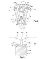
- Fig.3 details of a mounting of the PM permanent magnet at the beaks B1 and B2.
- This montage of the Fig.3 corresponds to a particular embodiment in which is provided an LM laminate.
- the LM laminate interposes between the upper face of the magnet PM and the lower faces of the nozzles B1, B2.
- the laminate LM is for example made of filled plastic, in a resin of epoxy resin type filled with glass fibers, a composite material or a deformable nonmagnetic metallic material.
- the function of the laminate to distribute the mechanical forces exerted on the top of the PM magnet and the beakers B1, B2 and to absorb by deformation a possible displacement of the magnet PM.
- the tests carried out by the inventive entity have shown that the centrifugal forces applying to the PM magnet can be significant.
- the magnet PM tends to move away from the axis of rotation of the rotor 11, under the effect of the centrifugal force, and a deformation of the nozzles B1, B2 to the outside of the rotor 11 could occur.
- the LM laminate contributes to a better distribution of the mechanical stresses between the beakers B1, B2 and by absorbing by deformation a possible displacement of the magnet PM thus reduces the risk of a rupture of the magnet PM and / or deformation beakers B1, B2.
- the tests carried out have shown that a laminate thickness of at least 0.1 mm is desirable for it to perform its function correctly.
- an inclination angle ⁇ of the lower face of the spout B1, B2, with respect to the upper face of the magnet PM is also provided.
- rounded is formed between the chamfered lower face of the spout B1, B2 and the adjoining substantially radial face forming the inner wall of the magnet housing.
- the radius R will preferably have a value between 0.2 and 0.9 times the depth L B of the beak B1, B2.
- chamfers or equivalent (rounded) CF are provided in this embodiment on the upper part of the magnet PM so as to avoid an edge contact of the magnet PM at the radius of radius R. will refer only to chamfers CF later in the description and in the appended claims, knowing that the term "chamfer” also covers equivalents such as rounded.
- the LM laminate allows a distribution of the mechanical forces on the two beakers B1 and B2 and can in some cases make unnecessary the need to chamfer the edges of PM magnets when its thickness is sufficient.
- the recess E1 comprises in its lower part, in the vicinity of the rotor shaft 11, reluctant spaces E12 which are, in this embodiment, spaces filled with air, left vacant by the magnet PM and which introducing a magnetic reluctance prevent local demagnetization of the PM magnet.
- the recesses E2 essentially have a reluctance and magnetic barrier function to control a magnetic defluxing flux through the central part of the rotor, i.e., in the magnetic mass between the bottom of the PM magnets and the shaft. A rotor. Note that these recesses E2 are filled in this particular embodiment. In some applications, they may be filled with non-magnetic or magnetic materials with a low relative permeability.
- the E3 recesses fulfill several functions. In general, their main function is to contribute, like the recesses E2, to the control of the magnetic defluxing flux, through the central part of the rotor, and to reduce the inertia of the rotor 11.
- these recesses E3 are filled with air. In some applications, they may also be filled with non-magnetic materials, even magnetic but with low density.
- the recesses E3 are shown here as being arranged radially in the rotor 11, centered between the consecutive magnets PM and symmetrical, it will be noted that in other embodiments of the invention, the recesses E3 can, especially in their upper part, being neither centered nor symmetrically shaped.
- other recesses are arranged in each pole, on either side of the recess E3.
- the recesses E4 contribute to reduce the inertia of the rotor 11 and are located in the alignment of the field lines, between them, so as to oppose as little as possible the passage of the magnetic flux of the magnets PM.
- the recesses E4 are two in number on each side of the recess E3.
- the number of recesses E4 may vary depending on the application and the available space. For example, their number may vary from 1 to 8, although 2 to 3 for the present invention is a good compromise.
- the practical rules for cutting the sheets make it necessary to keep a material width of between 1 and 2 times the thickness of the sheet, depending on the case.
- the minimum width of material to be preserved will be between 0.35 mm and 0.7 mm.
- the recess E3 comprises an upper trapezium E30 and a lower part E31.
- the upper trapezium E30 makes it possible to reduce the inertia of the rotor 11. It does, however, have an effect on the armature magnetic reaction and can also be dimensioned so as to participate in controlling it.
- the lower part E31 is the part of the recess E3 which contributes to the control of the magnetic flux of defluxing through the central part of the rotor 11.
- the part E31 together with the reluctant spaces E12 and the recess E2, makes it possible to control the path of the magnetic field lines in the central part of the rotor 11.
- the definition of the recesses E31 and E2 from the study of the distribution of the magnetic field lines in the pole makes it possible to obtain an optimally sized defluxing magnetic circuit.
- This magnetic loosening circuit must be dimensioned so as to allow a passage of the magnetic flux bypassing the magnet PM when a short-circuit situation appears in the stator windings, or when at high speed a current equal to the short-circuit current at most The circuit is injected into the stator windings so as to oppose the magnetic flux generated by the permanent magnets.
- Such a magnetic defluxing circuit prevents the appearance in the magnet PM of a demagnetizing field with an amplitude too high, likely to cause irreversible demagnetization of the PM magnet.
- the magnetic defluxing circuit must thus be calculated so as to obtain a correct polarization of the magnet PM.
- FIG. Fig.4 The equivalent magnetic circuit around a permanent magnet PM, in a short-circuit situation in the stator windings, is represented in FIG. Fig.4 .
- the LC field lines (shown in FIG. Fig.2 ) of the magnet PM do not pass through the stator of the machine. These LC field lines then close through a reluctance high magnetic Rh and magnetic low reluctances Rb1 and Rb2 of the magnetic circuit formed around the magnet PM.
- the high magnetic reluctance Rh is that of the path of the LC field lines through the beakers B1, B2 and the notch E10.
- the low magnetic reluctance Rb1 is that of the path of the LC field lines through the recesses E2 on either side of the bottom of the magnet PM, in the two adjacent poles.
- the low magnetic reluctance Rb2 is that of the LC field line paths through the ferrous constrictions S of the two poles, between the recesses E2 and the edges opposite the recesses E1.
- the constrictions formed by the portions B1, B2 and S operate globally in a saturation mode.
- the magnetic circuit comprises the FMM source in series with the internal reluctance R a and a magnetic flux reluctance R f substantially equivalent to the three reluctances Rh, Rb1 and Rb2 in parallel.
- the magnetization curve has substantially the shape of a straight line as shown in FIG. Fig.5 .
- B a is the magnetic induction of the magnet PM
- H a is the magnetic field applied to PM
- B r is the remanent magnetic induction of PM
- ⁇ a is the magnetic permeability of PM.
- ⁇ can be between 1.3 and 4.
- the zS in which, as shown in Fig.2 , l a is the width of the magnet PM, h a is the height of PM and L zs is the length of PM.
- ⁇ min and ⁇ max for each type of magnet. Then, knowing the reluctance R a PM magnets selected for the machine, a global deflux circuit reluctance R f can be determined from the inequality (12). Once the value of the overall deflection circuit reluctance R f has been determined, it is possible to optimize the distribution thereof between Rh, Rb1 and Rb2 so as to obtain the desired performances.
- the bridge BR is dimensionally defined by its height H and its length L.
- a bridge BR is necessary for reasons of mechanical strength of the rotor 11.
- BR bridge is continuous over the entire axial length of the rotor 11, so that the recess E3 does not open at any point of the circumferential surface of the rotor 11.
- the BR bridge is recessed with respect to the circumferential surface of the rotor and a wider air gap is obtained at the BR bridge between the stator 10 and the rotor 11.
- the bridge BR can be made discontinuously leaving the opening E3 opening on the outside, the circumferential surface rotor 11, for example, a plate on two.
- variable air gap between the rotor 11 and the stator 10, visible at Figs.1 , 6a and 6b also contributes to a reduction of harmonics and therefore iron losses.
- the height H of the bridge BR will be between about 1 times the thickness of the sheet and approximately 1 times the width of the magnet has.
- the height of the bridge BR according to the invention will be here between about 0.35 mm and about 5 mm.
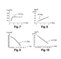
- Figs.9 and 10 show curves of torque Cmax and inertia I as a function of the length L of the bridge BR.
- the tests carried out by the inventive entity show that the best performance compromise between maximum torque and minimum inertia will be obtained for a length L of the BR bridge less than approximately 1.5 times the width l a (1xl a ) of the permanent magnets. PM.
- the minimum length L that the BR bridge can take will be of the order of 1, 5 times the thickness of the sheet, or about 0.520 mm for a sheet thickness of 0.35 mm.
- the invention has been described herein in the context of particular embodiments. The invention will find important applications in electric traction motors used in the automobile, for electric vehicles and hybrid vehicles. However, it should be clear that the invention will also find applications in other fields than the automotive field.
Landscapes
- Engineering & Computer Science (AREA)
- Power Engineering (AREA)
- Permanent Field Magnets Of Synchronous Machinery (AREA)
- Iron Core Of Rotating Electric Machines (AREA)
- Permanent Magnet Type Synchronous Machine (AREA)
Applications Claiming Priority (1)
| Application Number | Priority Date | Filing Date | Title |
|---|---|---|---|
| FR1052449A FR2958466B1 (fr) | 2010-03-31 | 2010-03-31 | Machine electrique tournante synchrone a aimants permanents et concentration de flux |
Publications (3)
| Publication Number | Publication Date |
|---|---|
| EP2372873A2 true EP2372873A2 (de) | 2011-10-05 |
| EP2372873A3 EP2372873A3 (de) | 2016-10-05 |
| EP2372873B1 EP2372873B1 (de) | 2021-07-21 |
Family
ID=43302114
Family Applications (1)
| Application Number | Title | Priority Date | Filing Date |
|---|---|---|---|
| EP11156917.4A Active EP2372873B1 (de) | 2010-03-31 | 2011-03-04 | Elektrische rotierende Synchronmaschine mit Dauermagneten und Strömungskonzentration |
Country Status (5)
| Country | Link |
|---|---|
| US (1) | US8508094B2 (de) |
| EP (1) | EP2372873B1 (de) |
| JP (1) | JP5961344B2 (de) |
| CN (1) | CN102208853B (de) |
| FR (1) | FR2958466B1 (de) |
Cited By (5)
| Publication number | Priority date | Publication date | Assignee | Title |
|---|---|---|---|---|
| EP2595282A2 (de) * | 2011-11-16 | 2013-05-22 | Shin-Etsu Chemical Co., Ltd. | Rotor und Drehmaschine mit Permanentmagnet |
| JP2015503312A (ja) * | 2011-10-24 | 2015-01-29 | エルジー エレクトロニクス インコーポレイティド | 洗濯機 |
| EP2863518A3 (de) * | 2013-10-18 | 2016-04-27 | General Electric Company | Reduktion der Drehmomentwelligkeit in elektrischen Maschinen |
| EP3667869A4 (de) * | 2017-08-09 | 2020-07-29 | Gree Green Refrigeration Technology Center Co., Ltd. of Zhuhai | Tangentialmotor, tangentialmotorrotor und rotoreisenkern dafür |
| WO2025011951A1 (de) * | 2023-07-10 | 2025-01-16 | Magna powertrain gmbh & co kg | Rotor einer permanentmagneterregten elektrischen maschine |
Families Citing this family (28)
| Publication number | Priority date | Publication date | Assignee | Title |
|---|---|---|---|---|
| CN103023256B (zh) * | 2011-09-26 | 2017-03-01 | 辐射通量实验室私人有限公司 | 永磁电机 |
| CN103023255A (zh) * | 2011-09-26 | 2013-04-03 | 辐射通量实验室私人有限公司 | 电磁机 |
| FR2982093B1 (fr) * | 2011-10-27 | 2017-11-03 | Valeo Equip Electr Moteur | Rotor de machine electrique tournante et machine electrique tournante comprenant un rotor |
| FR2983658B1 (fr) * | 2011-12-01 | 2014-09-12 | Valeo Equip Electr Moteur | Rotor de machine electrique tournante et machine electrique tournante comprenant un tel rotor |
| US8987971B2 (en) * | 2011-12-02 | 2015-03-24 | General Electric Company | Rotor core for an electric machine |
| EP2607731B1 (de) * | 2011-12-19 | 2014-10-15 | Siemens Aktiengesellschaft | Magnetisches Radiallager mit sternförmig geblechtem Rotor |
| CN102780293A (zh) * | 2012-07-26 | 2012-11-14 | 岳群生 | 一种切向式永磁同步电动机转子 |
| CN102769347A (zh) * | 2012-07-26 | 2012-11-07 | 岳群生 | 一种混合式永磁同步电动机转子 |
| US9871418B2 (en) | 2012-11-01 | 2018-01-16 | General Electric Company | Sensorless electric machine |
| US9941775B2 (en) | 2012-11-01 | 2018-04-10 | General Electric Company | D-ring implementation in skewed rotor assembly |
| US9906108B2 (en) | 2012-11-01 | 2018-02-27 | General Electric Company | Sensorless electric machine |
| KR20140056848A (ko) * | 2012-11-01 | 2014-05-12 | 엘지전자 주식회사 | 로터, 이를 포함하는 모터 및/또는 전기자동차 구동장치 |
| US9641033B2 (en) | 2013-09-06 | 2017-05-02 | General Electric Company | Electric machine having offset rotor sections |
| FR3009140B1 (fr) * | 2013-07-29 | 2017-02-24 | Valeo Equip Electr Moteur | Rotor a aimants permanents |
| EP2838180B1 (de) * | 2013-08-16 | 2020-01-15 | Siemens Aktiengesellschaft | Läufer einer dynamoelektrischen rotatorischen Maschine |
| US9906082B2 (en) | 2013-09-06 | 2018-02-27 | General Electric Company | Electric machine having reduced torque oscillations and axial thrust |
| WO2015137790A2 (ru) * | 2014-03-14 | 2015-09-17 | Алдан Асанович САПАРГАЛИЕВ | Многовекторное индукционное сцепление и электрическая машина |
| CA2988383A1 (en) * | 2015-06-05 | 2016-12-08 | Aldan Asanovich Saparqaliyev | Electrical machine & electrical drive |
| US11139707B2 (en) | 2015-08-11 | 2021-10-05 | Genesis Robotics And Motion Technologies Canada, Ulc | Axial gap electric machine with permanent magnets arranged between posts |
| RU2018108629A (ru) | 2015-08-11 | 2019-09-12 | Дженезис Роботикс Энд Мотион Текнолоджиз Канада, Улс | Электрическая машина |
| GB2546482B (en) | 2016-01-14 | 2019-07-10 | Jaguar Land Rover Ltd | Electric machine apparatus |
| US11043885B2 (en) | 2016-07-15 | 2021-06-22 | Genesis Robotics And Motion Technologies Canada, Ulc | Rotary actuator |
| FR3059849B1 (fr) * | 2016-12-01 | 2019-05-17 | Institut Vedecom | Machine electrique comportant un rotor a aimants permanents interieurs inclines |
| US10516305B2 (en) * | 2017-05-23 | 2019-12-24 | Ford Global Technologies, Llc | Variable flux bridge for rotor of an electric machine |
| US10797546B2 (en) * | 2019-01-08 | 2020-10-06 | Borgwarner Inc. | Interior permanent magnet electric machine with flux distributing voids |
| JP7308441B2 (ja) | 2019-02-07 | 2023-07-14 | パナソニックIpマネジメント株式会社 | 電動工具 |
| DE102021202360A1 (de) * | 2021-03-11 | 2022-09-15 | Robert Bosch Gesellschaft mit beschränkter Haftung | Rotor einer elektrischen Maschine |
| EP4436011A4 (de) * | 2021-11-15 | 2025-03-05 | Nippon Steel Corporation | Rotorkern, rotor und elektrische drehmaschine |
Family Cites Families (17)
| Publication number | Priority date | Publication date | Assignee | Title |
|---|---|---|---|---|
| US4339874A (en) * | 1978-12-26 | 1982-07-20 | The Garrett Corporation | Method of making a wedge-shaped permanent magnet rotor assembly |
| FR2548843B1 (fr) * | 1983-07-07 | 1986-11-07 | Labinal | Perfectionnement aux machines tournantes a aimants au rotor |
| US4618792A (en) * | 1984-09-26 | 1986-10-21 | Westinghouse Electric Corp. | Dynamoelectric machine with a laminated pole permanent magnet rotor |
| JPH0540682Y2 (de) * | 1988-03-14 | 1993-10-15 | ||
| WO1993001340A1 (en) * | 1991-07-04 | 1993-01-21 | A.C.M. Azienda Costruzione Motori S.A.S. Di Racca Anita & C. | Drive device for the cylinder of a hosiery machine and rotor assembly for a brushless synchronous motor |
| JPH05344668A (ja) * | 1992-06-08 | 1993-12-24 | Fanuc Ltd | 同期電動機のロータ |
| US6005318A (en) * | 1994-02-04 | 1999-12-21 | Schelenker Enterprises Ltd. | Motor including embedded permanent-magnet rotor and method for making the same |
| JPH11196556A (ja) * | 1997-12-26 | 1999-07-21 | Mitsubishi Heavy Ind Ltd | 磁石モータ |
| JP2004104962A (ja) * | 2002-09-12 | 2004-04-02 | Toshiba Industrial Products Manufacturing Corp | 永久磁石式リラクタンス型回転電機 |
| JP2005354798A (ja) * | 2004-06-10 | 2005-12-22 | Fujitsu General Ltd | 電動機 |
| DE102005060116A1 (de) * | 2004-12-20 | 2006-07-06 | Danfoss Compressors Gmbh | Rotor für einen elektrischen Motor |
| JP2006254620A (ja) * | 2005-03-11 | 2006-09-21 | Matsushita Electric Ind Co Ltd | 永久磁石ロータ |
| WO2008078584A1 (ja) * | 2006-12-27 | 2008-07-03 | Kabushiki Kaisha Yaskawa Denki | 埋込磁石型モータ |
| WO2008137709A2 (en) * | 2007-05-04 | 2008-11-13 | A. O. Smith Corporation | Interior permanent magnet motor and rotor |
| FR2932618B1 (fr) * | 2008-06-16 | 2010-11-19 | Leroy Somer Moteurs | Rotor a aimants permanents et machine tournante comportant un tel rotor |
| JP5329902B2 (ja) * | 2008-10-10 | 2013-10-30 | アスモ株式会社 | 回転電機のロータ構造 |
| FR2963501B1 (fr) * | 2010-07-29 | 2012-08-31 | Valeo Equip Electr Moteur | Machine electrique tournante synchrone avec rotor a double excitation |
-
2010
- 2010-03-31 FR FR1052449A patent/FR2958466B1/fr active Active
-
2011
- 2011-03-04 EP EP11156917.4A patent/EP2372873B1/de active Active
- 2011-03-30 JP JP2011073939A patent/JP5961344B2/ja active Active
- 2011-03-30 US US13/076,274 patent/US8508094B2/en active Active
- 2011-03-31 CN CN201110079605.0A patent/CN102208853B/zh active Active
Non-Patent Citations (1)
| Title |
|---|
| None |
Cited By (7)
| Publication number | Priority date | Publication date | Assignee | Title |
|---|---|---|---|---|
| JP2015503312A (ja) * | 2011-10-24 | 2015-01-29 | エルジー エレクトロニクス インコーポレイティド | 洗濯機 |
| EP2595282A2 (de) * | 2011-11-16 | 2013-05-22 | Shin-Etsu Chemical Co., Ltd. | Rotor und Drehmaschine mit Permanentmagnet |
| EP2863518A3 (de) * | 2013-10-18 | 2016-04-27 | General Electric Company | Reduktion der Drehmomentwelligkeit in elektrischen Maschinen |
| US9742228B2 (en) | 2013-10-18 | 2017-08-22 | General Electric Company | Torque ripple reduction in electric machines |
| EP3667869A4 (de) * | 2017-08-09 | 2020-07-29 | Gree Green Refrigeration Technology Center Co., Ltd. of Zhuhai | Tangentialmotor, tangentialmotorrotor und rotoreisenkern dafür |
| US11387695B2 (en) | 2017-08-09 | 2022-07-12 | Gree Green Refrigeration Technology Center Co., Ltd. Of Zhuhai | Tangential motor, tangential motor rotor and rotor iron core thereof |
| WO2025011951A1 (de) * | 2023-07-10 | 2025-01-16 | Magna powertrain gmbh & co kg | Rotor einer permanentmagneterregten elektrischen maschine |
Also Published As
| Publication number | Publication date |
|---|---|
| CN102208853B (zh) | 2014-12-17 |
| EP2372873B1 (de) | 2021-07-21 |
| US8508094B2 (en) | 2013-08-13 |
| FR2958466B1 (fr) | 2017-09-08 |
| JP5961344B2 (ja) | 2016-08-02 |
| FR2958466A1 (fr) | 2011-10-07 |
| JP2011217602A (ja) | 2011-10-27 |
| CN102208853A (zh) | 2011-10-05 |
| US20120001511A1 (en) | 2012-01-05 |
| EP2372873A3 (de) | 2016-10-05 |
Similar Documents
| Publication | Publication Date | Title |
|---|---|---|
| EP2372873B1 (de) | Elektrische rotierende Synchronmaschine mit Dauermagneten und Strömungskonzentration | |
| EP2372872A2 (de) | Elektrische rotierende Synchronmaschine mit Dauermagneten und Flusskonzentration | |
| EP2786469B1 (de) | Rotor für eine elektrische drehende maschine und elektrische drehende maschine mit einem derartigen rotor | |
| EP2599197B1 (de) | Elektrische maschine mit synchroner drehung und einem hybriderregungsmotor | |
| WO2013060960A2 (fr) | Rotor de machine electrique tournante et machine electrique tournante comprenant un rotor | |
| EP2786470A2 (de) | Rotor für eine elektrische drehmaschine und elektrische drehmaschine mit einem derartigen rotor | |
| EP2622715B1 (de) | Elektrische drehende synchronmaschine mit einem doppelerregten rotor | |
| EP3152816A2 (de) | Flusskonzentrationsrotor mit permanentmagneten für eine elektrische drehmaschine | |
| EP2792053B1 (de) | Rotor für eine rotierende elektrische maschine und rotierende elektrische maschine mit einem derartigen rotor | |
| FR3004297A1 (fr) | Rotor a aimantation permanente pouvant lui etre donnee apres coup | |
| EP2425521A1 (de) | Elektrische drehmaschine mit kompensation der magnetischen reaktion der armatur | |
| EP2372874B1 (de) | Elektrische rotierende Synchronmaschine mit Dauermagneten und Strömungskonzentration | |
| WO2014195613A1 (fr) | Rotor de machine electrique tournante et machine electrique tournante comprenant un tel rotor | |
| EP2599198B1 (de) | Synchron rotierende elektrische maschine mit einem hybriderregungsrotor | |
| EP2777135B1 (de) | Rotor für eine elektrische drehmaschine und elektrische drehmaschine mit einem solchen rotor | |
| EP3229348B1 (de) | Rotor für eine elektrische maschine | |
| EP2599196A1 (de) | Elektrische synchronrotationsmaschine mit rotor mit doppelerregung | |
| EP3053262A2 (de) | Mehrphasige elektrische drehmaschine mit mindestens fünf phasen | |
| WO2010133796A1 (fr) | Machine vernier a aimants insérés | |
| EP2128962A2 (de) | Elektrisch umlaufende Maschine mit im Rotor eingebauten Magneten | |
| EP2781007A2 (de) | Rotor mit permanentmagneten für eine elektrische drehmaschine | |
| FR3162326A1 (fr) | Rotor à aimants permanents | |
| WO2014006294A1 (fr) | Machine electrique tournante a compensation de reaction magnetique d'induit | |
| FR2963504A1 (fr) | Machine electrique tournante synchrone avec rotor a double excitation |
Legal Events
| Date | Code | Title | Description |
|---|---|---|---|
| PUAI | Public reference made under article 153(3) epc to a published international application that has entered the european phase |
Free format text: ORIGINAL CODE: 0009012 |
|
| 17P | Request for examination filed |
Effective date: 20110304 |
|
| AK | Designated contracting states |
Kind code of ref document: A2 Designated state(s): AL AT BE BG CH CY CZ DE DK EE ES FI FR GB GR HR HU IE IS IT LI LT LU LV MC MK MT NL NO PL PT RO RS SE SI SK SM TR |
|
| AX | Request for extension of the european patent |
Extension state: BA ME |
|
| PUAL | Search report despatched |
Free format text: ORIGINAL CODE: 0009013 |
|
| AK | Designated contracting states |
Kind code of ref document: A3 Designated state(s): AL AT BE BG CH CY CZ DE DK EE ES FI FR GB GR HR HU IE IS IT LI LT LU LV MC MK MT NL NO PL PT RO RS SE SI SK SM TR |
|
| AX | Request for extension of the european patent |
Extension state: BA ME |
|
| RIC1 | Information provided on ipc code assigned before grant |
Ipc: H02K 21/14 20060101ALI20160826BHEP Ipc: H02K 1/27 20060101AFI20160826BHEP |
|
| STAA | Information on the status of an ep patent application or granted ep patent |
Free format text: STATUS: EXAMINATION IS IN PROGRESS |
|
| 17Q | First examination report despatched |
Effective date: 20181123 |
|
| GRAP | Despatch of communication of intention to grant a patent |
Free format text: ORIGINAL CODE: EPIDOSNIGR1 |
|
| STAA | Information on the status of an ep patent application or granted ep patent |
Free format text: STATUS: GRANT OF PATENT IS INTENDED |
|
| INTG | Intention to grant announced |
Effective date: 20210223 |
|
| GRAS | Grant fee paid |
Free format text: ORIGINAL CODE: EPIDOSNIGR3 |
|
| GRAA | (expected) grant |
Free format text: ORIGINAL CODE: 0009210 |
|
| STAA | Information on the status of an ep patent application or granted ep patent |
Free format text: STATUS: THE PATENT HAS BEEN GRANTED |
|
| AK | Designated contracting states |
Kind code of ref document: B1 Designated state(s): AL AT BE BG CH CY CZ DE DK EE ES FI FR GB GR HR HU IE IS IT LI LT LU LV MC MK MT NL NO PL PT RO RS SE SI SK SM TR |
|
| REG | Reference to a national code |
Ref country code: GB Ref legal event code: FG4D Free format text: NOT ENGLISH |
|
| REG | Reference to a national code |
Ref country code: CH Ref legal event code: EP |
|
| REG | Reference to a national code |
Ref country code: DE Ref legal event code: R096 Ref document number: 602011071394 Country of ref document: DE |
|
| REG | Reference to a national code |
Ref country code: AT Ref legal event code: REF Ref document number: 1413507 Country of ref document: AT Kind code of ref document: T Effective date: 20210815 |
|
| REG | Reference to a national code |
Ref country code: IE Ref legal event code: FG4D Free format text: LANGUAGE OF EP DOCUMENT: FRENCH |
|
| REG | Reference to a national code |
Ref country code: LT Ref legal event code: MG9D |
|
| REG | Reference to a national code |
Ref country code: NL Ref legal event code: MP Effective date: 20210721 |
|
| REG | Reference to a national code |
Ref country code: AT Ref legal event code: MK05 Ref document number: 1413507 Country of ref document: AT Kind code of ref document: T Effective date: 20210721 |
|
| PG25 | Lapsed in a contracting state [announced via postgrant information from national office to epo] |
Ref country code: HR Free format text: LAPSE BECAUSE OF FAILURE TO SUBMIT A TRANSLATION OF THE DESCRIPTION OR TO PAY THE FEE WITHIN THE PRESCRIBED TIME-LIMIT Effective date: 20210721 Ref country code: SE Free format text: LAPSE BECAUSE OF FAILURE TO SUBMIT A TRANSLATION OF THE DESCRIPTION OR TO PAY THE FEE WITHIN THE PRESCRIBED TIME-LIMIT Effective date: 20210721 Ref country code: FI Free format text: LAPSE BECAUSE OF FAILURE TO SUBMIT A TRANSLATION OF THE DESCRIPTION OR TO PAY THE FEE WITHIN THE PRESCRIBED TIME-LIMIT Effective date: 20210721 Ref country code: ES Free format text: LAPSE BECAUSE OF FAILURE TO SUBMIT A TRANSLATION OF THE DESCRIPTION OR TO PAY THE FEE WITHIN THE PRESCRIBED TIME-LIMIT Effective date: 20210721 Ref country code: NL Free format text: LAPSE BECAUSE OF FAILURE TO SUBMIT A TRANSLATION OF THE DESCRIPTION OR TO PAY THE FEE WITHIN THE PRESCRIBED TIME-LIMIT Effective date: 20210721 Ref country code: PT Free format text: LAPSE BECAUSE OF FAILURE TO SUBMIT A TRANSLATION OF THE DESCRIPTION OR TO PAY THE FEE WITHIN THE PRESCRIBED TIME-LIMIT Effective date: 20211122 Ref country code: NO Free format text: LAPSE BECAUSE OF FAILURE TO SUBMIT A TRANSLATION OF THE DESCRIPTION OR TO PAY THE FEE WITHIN THE PRESCRIBED TIME-LIMIT Effective date: 20211021 Ref country code: RS Free format text: LAPSE BECAUSE OF FAILURE TO SUBMIT A TRANSLATION OF THE DESCRIPTION OR TO PAY THE FEE WITHIN THE PRESCRIBED TIME-LIMIT Effective date: 20210721 Ref country code: LT Free format text: LAPSE BECAUSE OF FAILURE TO SUBMIT A TRANSLATION OF THE DESCRIPTION OR TO PAY THE FEE WITHIN THE PRESCRIBED TIME-LIMIT Effective date: 20210721 Ref country code: BG Free format text: LAPSE BECAUSE OF FAILURE TO SUBMIT A TRANSLATION OF THE DESCRIPTION OR TO PAY THE FEE WITHIN THE PRESCRIBED TIME-LIMIT Effective date: 20211021 Ref country code: AT Free format text: LAPSE BECAUSE OF FAILURE TO SUBMIT A TRANSLATION OF THE DESCRIPTION OR TO PAY THE FEE WITHIN THE PRESCRIBED TIME-LIMIT Effective date: 20210721 |
|
| PG25 | Lapsed in a contracting state [announced via postgrant information from national office to epo] |
Ref country code: PL Free format text: LAPSE BECAUSE OF FAILURE TO SUBMIT A TRANSLATION OF THE DESCRIPTION OR TO PAY THE FEE WITHIN THE PRESCRIBED TIME-LIMIT Effective date: 20210721 Ref country code: LV Free format text: LAPSE BECAUSE OF FAILURE TO SUBMIT A TRANSLATION OF THE DESCRIPTION OR TO PAY THE FEE WITHIN THE PRESCRIBED TIME-LIMIT Effective date: 20210721 Ref country code: GR Free format text: LAPSE BECAUSE OF FAILURE TO SUBMIT A TRANSLATION OF THE DESCRIPTION OR TO PAY THE FEE WITHIN THE PRESCRIBED TIME-LIMIT Effective date: 20211022 |
|
| REG | Reference to a national code |
Ref country code: DE Ref legal event code: R097 Ref document number: 602011071394 Country of ref document: DE |
|
| PG25 | Lapsed in a contracting state [announced via postgrant information from national office to epo] |
Ref country code: DK Free format text: LAPSE BECAUSE OF FAILURE TO SUBMIT A TRANSLATION OF THE DESCRIPTION OR TO PAY THE FEE WITHIN THE PRESCRIBED TIME-LIMIT Effective date: 20210721 |
|
| PLBE | No opposition filed within time limit |
Free format text: ORIGINAL CODE: 0009261 |
|
| STAA | Information on the status of an ep patent application or granted ep patent |
Free format text: STATUS: NO OPPOSITION FILED WITHIN TIME LIMIT |
|
| PG25 | Lapsed in a contracting state [announced via postgrant information from national office to epo] |
Ref country code: SM Free format text: LAPSE BECAUSE OF FAILURE TO SUBMIT A TRANSLATION OF THE DESCRIPTION OR TO PAY THE FEE WITHIN THE PRESCRIBED TIME-LIMIT Effective date: 20210721 Ref country code: SK Free format text: LAPSE BECAUSE OF FAILURE TO SUBMIT A TRANSLATION OF THE DESCRIPTION OR TO PAY THE FEE WITHIN THE PRESCRIBED TIME-LIMIT Effective date: 20210721 Ref country code: RO Free format text: LAPSE BECAUSE OF FAILURE TO SUBMIT A TRANSLATION OF THE DESCRIPTION OR TO PAY THE FEE WITHIN THE PRESCRIBED TIME-LIMIT Effective date: 20210721 Ref country code: EE Free format text: LAPSE BECAUSE OF FAILURE TO SUBMIT A TRANSLATION OF THE DESCRIPTION OR TO PAY THE FEE WITHIN THE PRESCRIBED TIME-LIMIT Effective date: 20210721 Ref country code: CZ Free format text: LAPSE BECAUSE OF FAILURE TO SUBMIT A TRANSLATION OF THE DESCRIPTION OR TO PAY THE FEE WITHIN THE PRESCRIBED TIME-LIMIT Effective date: 20210721 Ref country code: AL Free format text: LAPSE BECAUSE OF FAILURE TO SUBMIT A TRANSLATION OF THE DESCRIPTION OR TO PAY THE FEE WITHIN THE PRESCRIBED TIME-LIMIT Effective date: 20210721 |
|
| 26N | No opposition filed |
Effective date: 20220422 |
|
| PG25 | Lapsed in a contracting state [announced via postgrant information from national office to epo] |
Ref country code: IT Free format text: LAPSE BECAUSE OF FAILURE TO SUBMIT A TRANSLATION OF THE DESCRIPTION OR TO PAY THE FEE WITHIN THE PRESCRIBED TIME-LIMIT Effective date: 20210721 |
|
| PG25 | Lapsed in a contracting state [announced via postgrant information from national office to epo] |
Ref country code: MC Free format text: LAPSE BECAUSE OF FAILURE TO SUBMIT A TRANSLATION OF THE DESCRIPTION OR TO PAY THE FEE WITHIN THE PRESCRIBED TIME-LIMIT Effective date: 20210721 |
|
| REG | Reference to a national code |
Ref country code: CH Ref legal event code: PL |
|
| GBPC | Gb: european patent ceased through non-payment of renewal fee |
Effective date: 20220304 |
|
| REG | Reference to a national code |
Ref country code: BE Ref legal event code: MM Effective date: 20220331 |
|
| PG25 | Lapsed in a contracting state [announced via postgrant information from national office to epo] |
Ref country code: LU Free format text: LAPSE BECAUSE OF NON-PAYMENT OF DUE FEES Effective date: 20220304 Ref country code: LI Free format text: LAPSE BECAUSE OF NON-PAYMENT OF DUE FEES Effective date: 20220331 Ref country code: IE Free format text: LAPSE BECAUSE OF NON-PAYMENT OF DUE FEES Effective date: 20220304 Ref country code: GB Free format text: LAPSE BECAUSE OF NON-PAYMENT OF DUE FEES Effective date: 20220304 Ref country code: CH Free format text: LAPSE BECAUSE OF NON-PAYMENT OF DUE FEES Effective date: 20220331 |
|
| PG25 | Lapsed in a contracting state [announced via postgrant information from national office to epo] |
Ref country code: BE Free format text: LAPSE BECAUSE OF NON-PAYMENT OF DUE FEES Effective date: 20220331 |
|
| P01 | Opt-out of the competence of the unified patent court (upc) registered |
Effective date: 20230528 |
|
| PG25 | Lapsed in a contracting state [announced via postgrant information from national office to epo] |
Ref country code: HU Free format text: LAPSE BECAUSE OF FAILURE TO SUBMIT A TRANSLATION OF THE DESCRIPTION OR TO PAY THE FEE WITHIN THE PRESCRIBED TIME-LIMIT; INVALID AB INITIO Effective date: 20110304 |
|
| PG25 | Lapsed in a contracting state [announced via postgrant information from national office to epo] |
Ref country code: MK Free format text: LAPSE BECAUSE OF FAILURE TO SUBMIT A TRANSLATION OF THE DESCRIPTION OR TO PAY THE FEE WITHIN THE PRESCRIBED TIME-LIMIT Effective date: 20210721 Ref country code: CY Free format text: LAPSE BECAUSE OF FAILURE TO SUBMIT A TRANSLATION OF THE DESCRIPTION OR TO PAY THE FEE WITHIN THE PRESCRIBED TIME-LIMIT Effective date: 20210721 |
|
| PG25 | Lapsed in a contracting state [announced via postgrant information from national office to epo] |
Ref country code: TR Free format text: LAPSE BECAUSE OF FAILURE TO SUBMIT A TRANSLATION OF THE DESCRIPTION OR TO PAY THE FEE WITHIN THE PRESCRIBED TIME-LIMIT Effective date: 20210721 |
|
| PG25 | Lapsed in a contracting state [announced via postgrant information from national office to epo] |
Ref country code: MT Free format text: LAPSE BECAUSE OF FAILURE TO SUBMIT A TRANSLATION OF THE DESCRIPTION OR TO PAY THE FEE WITHIN THE PRESCRIBED TIME-LIMIT Effective date: 20210721 |
|
| PGFP | Annual fee paid to national office [announced via postgrant information from national office to epo] |
Ref country code: DE Payment date: 20260313 Year of fee payment: 16 |
|
| PGFP | Annual fee paid to national office [announced via postgrant information from national office to epo] |
Ref country code: FR Payment date: 20260331 Year of fee payment: 16 |