EP2372901A2 - Elektrisches Maschinensicherheitssystem - Google Patents
Elektrisches Maschinensicherheitssystem Download PDFInfo
- Publication number
- EP2372901A2 EP2372901A2 EP11159968A EP11159968A EP2372901A2 EP 2372901 A2 EP2372901 A2 EP 2372901A2 EP 11159968 A EP11159968 A EP 11159968A EP 11159968 A EP11159968 A EP 11159968A EP 2372901 A2 EP2372901 A2 EP 2372901A2
- Authority
- EP
- European Patent Office
- Prior art keywords
- coils
- electrical machine
- magnet assembly
- current
- current signal
- Prior art date
- Legal status (The legal status is an assumption and is not a legal conclusion. Google has not performed a legal analysis and makes no representation as to the accuracy of the status listed.)
- Withdrawn
Links
- 238000000034 method Methods 0.000 claims description 24
- 230000005389 magnetism Effects 0.000 claims description 5
- 238000001514 detection method Methods 0.000 claims description 3
- 230000005672 electromagnetic field Effects 0.000 claims description 3
- 239000000696 magnetic material Substances 0.000 claims description 3
- 230000004044 response Effects 0.000 claims description 3
- 125000004122 cyclic group Chemical group 0.000 claims description 2
- 230000001052 transient effect Effects 0.000 claims description 2
- 238000004804 winding Methods 0.000 description 17
- 239000000463 material Substances 0.000 description 7
- 238000013021 overheating Methods 0.000 description 6
- 230000004907 flux Effects 0.000 description 4
- 230000008569 process Effects 0.000 description 4
- 238000013461 design Methods 0.000 description 3
- 231100001261 hazardous Toxicity 0.000 description 3
- 238000010438 heat treatment Methods 0.000 description 3
- 230000008901 benefit Effects 0.000 description 2
- 230000005284 excitation Effects 0.000 description 2
- 238000002347 injection Methods 0.000 description 2
- 239000007924 injection Substances 0.000 description 2
- 238000012545 processing Methods 0.000 description 2
- 239000000243 solution Substances 0.000 description 2
- 239000007858 starting material Substances 0.000 description 2
- 230000002411 adverse Effects 0.000 description 1
- 230000004888 barrier function Effects 0.000 description 1
- 230000015556 catabolic process Effects 0.000 description 1
- 238000004891 communication Methods 0.000 description 1
- 230000000295 complement effect Effects 0.000 description 1
- 238000006731 degradation reaction Methods 0.000 description 1
- 230000001419 dependent effect Effects 0.000 description 1
- 238000003745 diagnosis Methods 0.000 description 1
- 230000000694 effects Effects 0.000 description 1
- 238000005516 engineering process Methods 0.000 description 1
- 230000000977 initiatory effect Effects 0.000 description 1
- 239000011810 insulating material Substances 0.000 description 1
- 150000002505 iron Chemical class 0.000 description 1
- 210000003127 knee Anatomy 0.000 description 1
- 238000005259 measurement Methods 0.000 description 1
- 239000002184 metal Substances 0.000 description 1
- 229910052751 metal Inorganic materials 0.000 description 1
- 230000000116 mitigating effect Effects 0.000 description 1
- 229910001172 neodymium magnet Inorganic materials 0.000 description 1
- 230000035699 permeability Effects 0.000 description 1
- 238000004393 prognosis Methods 0.000 description 1
- 229910000938 samarium–cobalt magnet Inorganic materials 0.000 description 1
Images

Classifications
-
- H—ELECTRICITY
- H02—GENERATION; CONVERSION OR DISTRIBUTION OF ELECTRIC POWER
- H02K—DYNAMO-ELECTRIC MACHINES
- H02K21/00—Synchronous motors having permanent magnets; Synchronous generators having permanent magnets
- H02K21/12—Synchronous motors having permanent magnets; Synchronous generators having permanent magnets with stationary armatures and rotating magnets
- H02K21/14—Synchronous motors having permanent magnets; Synchronous generators having permanent magnets with stationary armatures and rotating magnets with magnets rotating within the armatures
- H02K21/16—Synchronous motors having permanent magnets; Synchronous generators having permanent magnets with stationary armatures and rotating magnets with magnets rotating within the armatures having annular armature cores with salient poles
-
- H—ELECTRICITY
- H02—GENERATION; CONVERSION OR DISTRIBUTION OF ELECTRIC POWER
- H02K—DYNAMO-ELECTRIC MACHINES
- H02K11/00—Structural association of dynamo-electric machines with electric components or with devices for shielding, monitoring or protection
- H02K11/20—Structural association of dynamo-electric machines with electric components or with devices for shielding, monitoring or protection for measuring, monitoring, testing, protecting or switching
- H02K11/21—Devices for sensing speed or position, or actuated thereby
- H02K11/225—Detecting coils
-
- H—ELECTRICITY
- H02—GENERATION; CONVERSION OR DISTRIBUTION OF ELECTRIC POWER
- H02P—CONTROL OR REGULATION OF ELECTRIC MOTORS, ELECTRIC GENERATORS OR DYNAMO-ELECTRIC CONVERTERS; CONTROLLING TRANSFORMERS, REACTORS OR CHOKE COILS
- H02P29/00—Arrangements for regulating or controlling electric motors, appropriate for both AC and DC motors
- H02P29/02—Providing protection against overload without automatic interruption of supply
- H02P29/024—Detecting a fault condition, e.g. short circuit, locked rotor, open circuit or loss of load
- H02P29/0241—Detecting a fault condition, e.g. short circuit, locked rotor, open circuit or loss of load the fault being an overvoltage
-
- H—ELECTRICITY
- H02—GENERATION; CONVERSION OR DISTRIBUTION OF ELECTRIC POWER
- H02P—CONTROL OR REGULATION OF ELECTRIC MOTORS, ELECTRIC GENERATORS OR DYNAMO-ELECTRIC CONVERTERS; CONTROLLING TRANSFORMERS, REACTORS OR CHOKE COILS
- H02P29/00—Arrangements for regulating or controlling electric motors, appropriate for both AC and DC motors
- H02P29/60—Controlling or determining the temperature of the motor or of the drive
- H02P29/62—Controlling or determining the temperature of the motor or of the drive for raising the temperature of the motor
-
- H—ELECTRICITY
- H02—GENERATION; CONVERSION OR DISTRIBUTION OF ELECTRIC POWER
- H02P—CONTROL OR REGULATION OF ELECTRIC MOTORS, ELECTRIC GENERATORS OR DYNAMO-ELECTRIC CONVERTERS; CONTROLLING TRANSFORMERS, REACTORS OR CHOKE COILS
- H02P29/00—Arrangements for regulating or controlling electric motors, appropriate for both AC and DC motors
- H02P29/60—Controlling or determining the temperature of the motor or of the drive
- H02P29/66—Controlling or determining the temperature of the rotor
- H02P29/662—Controlling or determining the temperature of the rotor the rotor having permanent magnets
-
- H—ELECTRICITY
- H02—GENERATION; CONVERSION OR DISTRIBUTION OF ELECTRIC POWER
- H02K—DYNAMO-ELECTRIC MACHINES
- H02K2213/00—Specific aspects, not otherwise provided for and not covered by codes H02K2201/00 - H02K2211/00
- H02K2213/09—Machines characterised by the presence of elements which are subject to variation, e.g. adjustable bearings, reconfigurable windings, variable pitch ventilators
Definitions
- the present invention relates to electrical machines and more particularly to permanent magnet electrical machines for which there is desired to be some form of fail-safe or fault-tolerant capability.
- Permanent magnet electrical machines are often favoured for use in applications in which high power density is required for motor or generator applications.
- Common applications for such machines include land vehicles, aircraft, water-borne vessels and fixed industrial applications.
- a conventional permanent magnet electrical machine has an array of permanent magnets and a further array of magnetic coils (often called windings), usually disposed within slots in an armature of high permeability material, such as laminated iron.
- the magnetic coils commonly form a ring-shaped array on a stator around a rotor which carries the permanent magnets. Turning the rotor relative to the stator creates currents in the coils, allowing the electrical machine to be used as a generator. Conversely, alternating current can be applied to the coils to cause the rotor to turn, allowing the electrical machine to be used as a motor.
- a second methodology is described in International Patent Application PCT/GB2004/002601 (Publication No. WO 2005/011078 ), wherein it is proposed to inject a nullifying current into the unfaulted turns of the faulted phase.
- the magnitude and phase of the injected current should be such that the net flux (i.e. that from the permanent magnets plus that from the current in the stator winding) linking the faulted turn(s) is close to zero. In such circumstances current flowing in the shorted turns will be close to zero and so the risk of overheating should be minimal.
- the current in the unfaulted turns of the faulted phase should also not be significantly greater than rated current, thus mitigating against the risk of overheating within those turns.
- An electrical machine system comprising a permanent magnet assembly having a magnetic field and a plurality of conductive coils, the magnet assembly and coils arranged for relative rotation between the coils and magnetic field in the manner of an electrical generator or motor, the system further comprising a current injector electrically connected to said coils and arranged selectively to supply a current signal thereto, the current signal being asynchronous with the frequency of rotation between the permanent magnet assembly and coils so as to heat and thereby demagnetise one or more magnet within said permanent magnet assembly.
- the permanent magnets have a normal operating magnetism and the current injector is arranged to supply a current signal having frequency characteristics and for a duration sufficient to demagnetise the permanent magnet by at least 80%, typically 90% or more, of its normal operational magnetism.
- the current signal may irreversibly demagnetise the permanent magnet to such an extent.
- the current injector may be arranged to supply a current signal for a duration sufficient to raise the temperature of one or more magnets within the permanent magnet assembly to above or equal to Curie temperature.
- the temperature rise may be achieved by induced currents within the permanent magnets.
- the duration of application of the current signal may be between 1 and 90 seconds, more particularly between 10 and 90 seconds and preferably between 10 and 60 seconds.
- the permanent magnet(s) may be suitably demagnetised within this timeframe.
- a plurality of sensors is provided for detecting one or more operational variables of the system in use.
- a controller may be arranged to receive sensor readings and to control application of the current signal by the injector in dependence upon the received readings.
- the controller may control application of the current signal by the injector in a transient manner based upon readings of said operational variable from said sensor. Alternatively the controller may initiate a predetermined control sequence in response to detection of an operational variable value indicative of a fault by said sensor.
- the voltage induced in the stator windings by the permanent magnet rotation is detected or measured. This may be used to determine the state of magnetisation of the permanent magnet.
- the sensor senses the temperature of one or more magnets within the magnet assembly. The controller may be arranged to cease supply of current to the coils by the injector once the sensed potential and/or temperature meets or exceeds a predetermined value, which may be indicative of the desired demagnetisation of the permanent magnets.
- the permanent magnet assembly may be spaced from the conductive coils by an air gap and the current injector may be arranged to supply a current signal to said coils which generates a harmonic-rich electromagnetic field within the air gap.
- the electromagnetic field may be asynchronous and/or contra-rotating with respect to the relative rotation between the magnet assembly and coils.
- the supplied current signal may have a waveform which varies in a cyclic manner relative to the frequency of rotation between permanent magnet assembly and the coils.
- the supplied current signal may also vary in magnitude over a further time domain relative to duration for which the current signal is supplied to the coils.
- the signal may sweep a frequency range over the demagnetisation process.
- the coils comprise a plurality of groups, each group being associated with an electrical phase of the system, the system further comprising a plurality of injectors, each injector being electrically connected to a respective group of coils for supply of said current signal thereto.
- the system comprises a rotor and stator assembly.
- the rotor may comprise the permanent magnet assembly and the stator may comprise the plurality of conductive coils.
- the coils of the stator may be arranged in a ring-shaped array with the rotor being mounted within said ring.
- the present invention provides for an electrical machine that is fail-safe in that the permanent magnets can be demagnetised so as to leave the rotor in a magnetically inert state such that significant voltages or currents can no longer be induced in the windings by relative rotation between the rotor and stator.
- the present invention makes use of the material properties of the permanent magnet(s) which allow for degradation of the magnetic properties with elevated temperature.
- Figure 1 shows a cross-section through a permanent magnet electrical machine 10 which has a stator 12 arranged circumferentially around a rotor 14.
- the rotor 14 carries an array of permanent magnets 16 magnetised in a generally radial direction and alternating in polarity, so that the rotor 14 provides an alternating array of north and south magnetic poles, indicated in Figure 1 by the letters N and S.
- the array is circular so as to provide a ring of permanent magnets of alternating ploarity.
- a total of twenty poles are provided around the rotor 14.
- the rotor is mounted by means of appropriate bearings to turn about the axis 18.
- the stator 12 (or armature) has a ring of slots 20 formed therein, separated by teeth 22.
- Each pair of adjacent slots 20 accommodates a winding in the form of a coil 24.
- Each coil 24 is located around the tooth 22 which separates the slots 20.
- the next pair of slots 20 accommodates another coil, and so on around the stator 12.
- a stator having twenty four slots, as shown in Fig. 1 will accommodate twelve coils. These can be divided into three groups of four coils to provide three electrical phases.
- the coil axis is disposed along the tooth 22, radially from the axis 18 of the machine 10.
- the individual coils 24 are connected to an electrical control means, which in this embodiment takes the form of a power electronics converter 26. Whilst only a single power electronics converter is shown in figure 1 , it will be appreciated that in a practical embodiment, three such devices would typically be provided, each being dedicated to a phase of the electrical machine and thus being connected to only a subset of the total windings 24 which relate to that phase.
- any form of supervisory controller which is capable of the processing steps described below may be used which may or may not operate in conjunction with a power electronics converter. Accordingly the controller typically comprises one or more processors which, for the purpose of the present invention, may be defined in terms of the function they perform rather than the exact physical make-up or location thereof.
- a sensor is shown schematically at 28 which is in communication either directly or indirectly (via a network and/or other electrical equipment) to the controller 26.
- One or more sensors 28 may be mounted at any appropriate location(s) in order to measure one or more operational variables for the electrical machine 10.
- Such sensing means may be used to determine, for example, any or any combination of: rotational speed or frequency of the rotor; frequency, phase or harmonic content of the voltage and/or current in coils 24; temperature at one or more locations of the rotor; torque supplied to or from the electrical machine; and/or vibration or other unwanted motion of the rotor or components attached thereto.
- Additional or alternative sensing means may be provided to determine the electromotive force (EMF) in one or more coils 24.
- EMF electromotive force
- Such sensing means may be implemented by way of control means 26 or else using conventional voltage sensing or determination equipment.
- Figure 1 shows an electrical machine topology in which the stator 12 and the associated coils 24 are stationary and located outside the permanent magnets of the radial flux internal rotating rotor 14.
- the technique applies equally to other topologies such as inside-out and axial flux machines. Accordingly, the principles which will now be described in relation to the embodiment of figure 1 can be applied also to machines with varying numbers of permanent magnets (or phases thereof), magnetic poles and/or coils; and/or machines in which the permanent magnet system is located radially outside the magnetic coils, and/or to machines in which the magnetic coils rotate past fixed permanent magnets.
- a machine of the type illustrated in Fig. 1 may be operated at a rotational speed of up to or exceeding 6000 rpm, giving rise to an output frequency in excess of 1000 Hz.
- Such applications may be suited to use for example as a starter/generator within a gas turbine engine.
- a significant problem with this type of machine is that the permanent magnets 16 can continue to rotate once the short-circuit or other fault has occurred and thus potentially large currents are induced in the faulted turns of the stator windings 24.
- the present invention aims to remove the source of excitation which drives this potentially hazardous fault current by demagnetising the permanent magnets irreversibly or only partially reversibly to such an extent that any currents induced anywhere in the stator windings of the machine are of relatively small magnitude. Such a magnitude would be at least less than rated current for the machine and thus create no risk of over heating.
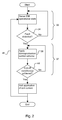
- a basic feedback loop 32 is operated, by which sensor readings of operational variables are monitored by controller 26.
- the controller compares the sensor readings at 34 to one or more predetermined criteria indicative of a fault, such as a short-circuit within windings 24.
- the controller may conduct some processing of the sensor-derived data for fault diagnosis or prognosis purposes. Accordingly the controller can determine a severity or type of detected fault.
- the controller proceeds to apply a demagnetisation control scheme at 36 to demagnetise the rotor permanent magnets as will be described below.
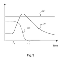
- Figure 3 shows schematic plots of temperature 38 and magnetic strength (moment) 40 for permanent magnets 16 within the machine. During normal operation, temperature and magnetic strength are substantially constant, indicative of substantially steady state operation up to time T 1 . At T 1 the controller instigates the demagnetisation failsafe scheme according to step 36 of Fig. 2 .
- thermal demagnetisation can be achieved in practice by deliberately, and dramatically, increasing the loss generated in the magnets themselves as a result of induced eddy currents. This can be achieved by using the phases of the power electronics converter 26 to drive stator phase currents, the magnetic field of which induces eddy-currents (primarily in the permanent magnets) which heat the permanent magnets of the rotor such that their working line/stored energy product reduces with increasing temperature.
- the controller may apply a predetermined current signal dependent on the rotational speed or frequency of the machine rotor. Additionally or alternatively, the controller may enter a feedback loop 37 in which sensor readings are used to determine the appropriate stator phase currents to be applied. For example, the temperature of the magnets may be monitored and the stator currents may be driven to achieve a desired temperature rise for a predetermined time duration. Additionally or alternatively, the residual EMF induced in the stator windings may be monitored and stator currents driven accordingly. Additionally or alternatively, the rotational speed or frequency of the rotor may be monitored and the current signal frequency altered accordingly.
- the state of magnetisation of the permanent magnet rotor may be determined there-from. This could be achieved using observing means whilst the injection current is applied/flowing or else by initiating a, typically brief, pause in the injected current in order to measure the EMF induced in the coils directly.
- Such techniques may be beneficially practicable for the arrangement of figure 1 , since complex electrical connections with the rotor may be avoided for the purpose of assessing demagnetisation.
- An algorithm can be used to determine magnetic strength of the permanent magnets based on the determination of the voltage induced in the coils.
- Such an algorithm may be generated theoretically or empirically.
- the determination that the permanent magnets are suitably demagnetised may require the induced voltage to drop below a predetermined threshold value.
- the effect of the driven current in the coils 24 is shown by the temperature increase after time T 1 .
- the faulted phase of a short-circuited winding may at least in part be used to drive the stator phase currents.
- the aim of the control sequence is to thermally demagnetise the permanent magnets by raising the temperature well above a normal operating range but safely below a temperature which would cause catastrophic loss of mechanical integrity of the magnets or associated rotor or stator components.
- all magnetic materials lose their entire magnetic properties at their so-called Curie Temperature.
- the Curie temperature for the permanent magnets of this embodiment is shown at 42 in Fig. 3 . Transiently taking a material above its Curie Temperature and then allowing the material to cool down results in no residual permanent magnetic properties.
- the controller controls the elevation of the magnet temperature to or slightly above the Curie Temperature of the magnetic material throughout the entire magnet body.
- demagnetisation can typically be achieved by taking the magnet beyond its manufacturer's specified operation range by some 50-100°C. Accordingly it may not be necessary to meet or exceed the Curie temperature throughout the entirety of the permanent magnet material for effective demagnetisation to occur.
- a shorted phase of a permanent magnet machine may experience currents which are multiple times the rated current if left unchecked, which for a gas turbine engine starter/generator could achieve several thousand amps.
- the permanent magnets are degraded by at least 90% of their normal magnetisation.
- a basic tenet of permanent magnet machine design is to minimise the rotor loss by removing harmonics from the airgap field etc.
- every effort is generally made to produce a field which is essentially stationary with respect to the rotor itself, thus minimising losses in the rotor magnet.
- there are inevitable harmonic components in the field but their impact on rotor loss is managed such that the rotor does not experience significant temperature rise.
- the frequency, phase and harmonic content of the stator current can be modified dramatically to produce a grossly asynchronous (possibly contra-rotating) and harmonic rich airgap field (recalling that the rotor is driven by the prime mover at engine shaft speed in the case of a gas-turbine).
- a typical increase in losses of between 1 and 2 orders of magnitude could be achieved by applying a current waveform which grossly exacerbates rotor loss.
- the inventor has advantageously determined that the magnitude of these stator currents need not be greater than those used in full load steady-state operation. Accordingly injected currents can be at or below rated current for the power electronic converter. Instead the phase rotation, frequency and/or harmonic content can be controlled to give rise to the losses required for heating the permanent magnet assembly. In this way the power electronics converter can be rated for steady state operation and will not require uprating for this demagnetisation scheme.
- one or more of the phases of the machine can, initially, be used to supply the necessary current to the other phase(s). This technique is intended to be used during the initial period of demagnetisation while the permanent magnets retain a significant part of their original permanent magnetism.
- the controller determines that sufficient demagnetisation throughout the permanent magnets has been achieved, for example, by temperature or EMF measurement as described above. This is indicated as time T 2 in figure 3 .
- the temperature rise may be determined by locating temperature sensor(s) at a distance removed from the surface of one or more of the permanent magnets so as to measure the temperature within the body of the magnet.
- the safe timeframe for achieving the desired demagnetisation is between single numbers of seconds and tens of seconds, preferably between 1 and 30 seconds and typically in a range of 5 to 20 seconds.
- the new scheme is independent of, but complementary to, the existing methods used for avoiding over-currents in the stator winding.
- the new scheme can therefore be used with or instead of the existing methods.
- the present invention will allow for a failsafe capability that is invoked in the event of a hazardous or uncontrolled mode of operation.
- the steady-state design of the electrical machine could be adjusted to take advantage of the ideas of this invention.
- lower temperature grade magnets could be considered as these will require less heating to demagnetise them (e.g. replace SmCo by NdFeB).
- the permanent magnets may be less subdivided so that induced eddy-currents and resultant heating are larger in the steady-state resulting in higher operating temperature (i.e. closer to their Curie point).
- the thermal resistance between the permanent magnets and the rotor body might be increased so that (a) in the steady-state they run hotter than conventional configuration and (b) they are thus easier to heat towards their Curie temperature when required.
- an insulating material or thermal barrier material may be provided at 30 at the interface between the magnets 16 and the rotor body 14 to which they are mounted.
- the eddy-currents do not have to be induced solely in the permanent magnets. Any adjacent seat of eddy-currents will help e.g. in the metal banding that is used to retain the permanent magnets (of a surface-mounted design) in close contact with the rotor body at all times.
- the demagnetising currents in the various phases could be coordinated in such a way as to achieve additional goals e.g. electromagnetic torque ripple minimisation.
- the hardware and control scheme described above may also be used as a failsafe for faults other than short circuits within the machine windings, such as, for example, in a situation in which one or more of the power electronic converter phases has been lost and the control system operating on the unfaulted phases cannot compensate for the faulted phase.
- the present invention may be used to accommodate any such instances in which the consequences of a fault are considered critical to safety or the integrity of a larger system.
- the method could be adapted to non-fault-tolerant permanent magnet electrical machines where it is required to give them some degree of fail-safe or fault-tolerant capability.
Landscapes
- Engineering & Computer Science (AREA)
- Power Engineering (AREA)
- Microelectronics & Electronic Packaging (AREA)
- Control Of Motors That Do Not Use Commutators (AREA)
- Reciprocating, Oscillating Or Vibrating Motors (AREA)
Applications Claiming Priority (1)
| Application Number | Priority Date | Filing Date | Title |
|---|---|---|---|
| GBGB1005178.7A GB201005178D0 (en) | 2010-03-29 | 2010-03-29 | Electrical machine safety system |
Publications (2)
| Publication Number | Publication Date |
|---|---|
| EP2372901A2 true EP2372901A2 (de) | 2011-10-05 |
| EP2372901A3 EP2372901A3 (de) | 2015-02-11 |
Family
ID=42228462
Family Applications (1)
| Application Number | Title | Priority Date | Filing Date |
|---|---|---|---|
| EP11159968.4A Withdrawn EP2372901A3 (de) | 2010-03-29 | 2011-03-28 | Elektrisches Maschinensicherheitssystem |
Country Status (3)
| Country | Link |
|---|---|
| US (1) | US8648575B2 (de) |
| EP (1) | EP2372901A3 (de) |
| GB (1) | GB201005178D0 (de) |
Cited By (6)
| Publication number | Priority date | Publication date | Assignee | Title |
|---|---|---|---|---|
| EP2779421A3 (de) * | 2013-03-15 | 2015-12-02 | Hamilton Sundstrand Corporation | Integrierter Startergenerator |
| EP3012438A1 (de) * | 2014-10-21 | 2016-04-27 | Rolls-Royce plc | Gasturbinentriebwerks- kraftstoffsystem |
| EP2790320A3 (de) * | 2013-04-11 | 2016-05-25 | Rolls-Royce plc | Betriebsverfahren für elektrisches Flugzeugsystem |
| EP2605373A3 (de) * | 2011-12-13 | 2016-08-03 | Samsung Electronics Co., Ltd | Motor |
| WO2019101915A1 (de) * | 2017-11-23 | 2019-05-31 | Siemens Aktiengesellschaft | Elektrische maschine mit erhöhter betriebssicherheit |
| EP3618263B1 (de) * | 2018-08-27 | 2025-07-09 | General Electric Company | Motor mit permanentmagnetelektromaschine |
Families Citing this family (17)
| Publication number | Priority date | Publication date | Assignee | Title |
|---|---|---|---|---|
| EP2463992B1 (de) * | 2010-12-08 | 2015-07-29 | Siemens Aktiengesellschaft | Permanentmagneterregter Elektromotor mit Heizeinrichtung und Betriebsverfahren |
| KR20140003851A (ko) * | 2012-06-29 | 2014-01-10 | 삼성전기주식회사 | 모터 및, 그의 로터와 스테이터 어셈블리 사이 공극 거리측정 및 제어방법 |
| JP5695013B2 (ja) * | 2012-11-02 | 2015-04-01 | 本田技研工業株式会社 | 回転電機の磁石温度推定装置及び磁石温度推定方法 |
| US20150022126A1 (en) * | 2013-07-18 | 2015-01-22 | GM Global Technology Operations LLC | Method and apparatus for monitoring a permanent magnet electric machine |
| US9698660B2 (en) | 2013-10-25 | 2017-07-04 | General Electric Company | System and method for heating ferrite magnet motors for low temperatures |
| US9602043B2 (en) * | 2014-08-29 | 2017-03-21 | General Electric Company | Magnet management in electric machines |
| EP3035504B1 (de) * | 2014-12-18 | 2017-07-26 | Rolls-Royce plc | Elektrische maschinen |
| CN106329863A (zh) * | 2015-07-09 | 2017-01-11 | 上海航天有线电厂有限公司 | 一种特定尺寸的直驱伺服电机 |
| US10519917B2 (en) * | 2017-04-25 | 2019-12-31 | Ford Global Technologies, Llc | Engine operation based on integrated starter-generator temperature |
| CN113394922B (zh) * | 2020-03-13 | 2022-06-14 | 中车永济电机有限公司 | 永磁电机调整方法、装置、设备以及存储介质 |
| DE102021205863A1 (de) * | 2021-06-10 | 2022-12-15 | Zf Friedrichshafen Ag | Verfahren zum Betreiben eines Leistungsstrangs |
| EP4106187A1 (de) * | 2021-06-14 | 2022-12-21 | ABB Schweiz AG | Verfahren zur aktualisierung eines thermischen modells eines elektromotors |
| CN117546403A (zh) * | 2021-09-22 | 2024-02-09 | 株式会社Ihi | 电动机械系统 |
| GB2627783A (en) * | 2023-03-01 | 2024-09-04 | Mercedes Benz Group Ag | An electric motor with temperature sensor, a corresponding method for operating the electric motor, and corresponding vehicle |
| US12381026B2 (en) * | 2023-06-13 | 2025-08-05 | Ford Global Technologies, Llc | Systems and methods for demagnetization of a permanent magnet rotor |
| GB2636154A (en) * | 2023-11-30 | 2025-06-11 | Zf Automotive Uk Ltd | Apparatus for use in recycling of electric motors and method of recycling an electric motor |
| CN121012253B (zh) * | 2025-10-27 | 2026-02-24 | 云梦山(常州)科技有限公司 | 一种具有防潮功能的航空用起动电机 |
Citations (1)
| Publication number | Priority date | Publication date | Assignee | Title |
|---|---|---|---|---|
| WO2005011078A1 (en) | 2003-07-12 | 2005-02-03 | Rolls-Royce Plc | Electrical machine |
Family Cites Families (27)
| Publication number | Priority date | Publication date | Assignee | Title |
|---|---|---|---|---|
| US4130769A (en) * | 1974-11-01 | 1978-12-19 | Canon Kabushiki Kaisha | Brushless DC motor |
| DE2730142C2 (de) * | 1977-07-04 | 1988-01-21 | Papst-Motoren GmbH & Co KG, 7742 St Georgen | Kollektorloser Gleichstrommotor der zweisträngigen Bauart |
| DE2907898A1 (de) * | 1979-03-01 | 1980-09-11 | Steingroever Erich Dr Ing | Vielpolige vorrichtung und verfahren zum magnetisieren von ringfoermigen dauermagneten |
| US4463314A (en) * | 1980-07-28 | 1984-07-31 | Westinghouse Electric Corp. | Earth field compensation for a magnetic detector by imparting a permanent magnetization to a magnetic material contiguous the detector |
| KR830000981B1 (ko) * | 1981-12-08 | 1983-05-18 | 이병윤 | 브러시 리스 직류 모우터 |
| JPS5941760A (ja) * | 1982-08-31 | 1984-03-08 | 株式会社東芝 | 磁気冷凍装置 |
| US4750821A (en) * | 1984-08-24 | 1988-06-14 | Canon Kabushiki Kaisha | Zoom lens assembly |
| US4920292A (en) * | 1986-08-29 | 1990-04-24 | Papst-Motoren Gmbh & Co. Kg | Motor having rotor capable of both stepped rotary and axial shift motions |
| US5099162A (en) * | 1987-07-22 | 1992-03-24 | Canon Kabushiki Kaisha | Coil of superconducting material for electric appliance and motor utilizing said coil |
| US5754025A (en) * | 1993-12-28 | 1998-05-19 | Sony Corporation | Iron core motor device |
| DE4414527C1 (de) * | 1994-04-26 | 1995-08-31 | Orto Holding Ag | Elektronisch kommutierte Gleichstrommaschine |
| TW328190B (en) * | 1994-06-14 | 1998-03-11 | Toshiba Co Ltd | Control device of brushless motor and method of fault detection and air conditioner |
| US5798623A (en) * | 1996-02-12 | 1998-08-25 | Quantum Corporation | Switch mode sine wave driver for polyphase brushless permanent magnet motor |
| SE516499C2 (sv) * | 1996-05-30 | 2002-01-22 | Vilmos Toeroek | Självstartande borstlös elektrisk motor |
| FR2754104B1 (fr) * | 1996-10-01 | 1998-10-30 | Braillon Magnetique Sa | Procede de demagnetisation pour dispositifs electro-permanents |
| DE19752884A1 (de) * | 1997-11-28 | 1999-06-10 | Bosch Gmbh Robert | Förderaggregat für Kraftstoff |
| JPH11356088A (ja) * | 1998-06-08 | 1999-12-24 | Matsushita Electric Ind Co Ltd | ブラシレスモータの駆動装置 |
| US6313560B1 (en) | 1999-12-20 | 2001-11-06 | Pratt & Whitney Canada Corp. | Thermally protected electric machine |
| DE10124436A1 (de) * | 2001-05-18 | 2002-11-28 | Bosch Gmbh Robert | Bürstenloser Gleichstromantrieb |
| AU2003268751A1 (en) * | 2002-10-11 | 2004-05-04 | Mitsuba Corporation | Control method of generator |
| JP2005012914A (ja) * | 2003-06-19 | 2005-01-13 | Koyo Seiko Co Ltd | 電動機のドライバ |
| FR2860108B1 (fr) * | 2003-09-24 | 2007-01-19 | Johnson Contr Automotive Elect | Dispositif de redressement synchrone et machine electrique synchrone mettant en oeuvre le dispositif |
| AT7524U1 (de) * | 2003-10-31 | 2005-04-25 | Magna Steyr Fahrzeugtechnik Ag | Aktuator mit einem elektrischen stellmotor und steuerbare reibungskupplung mit einem solchen |
| JP4030571B1 (ja) * | 2006-10-26 | 2008-01-09 | 有限会社ケイ・アールアンドデイ | 単相交流同期モータ |
| GB0719814D0 (en) * | 2007-10-05 | 2007-11-21 | Rolls Royce Plc | Flux-switching machine |
| JP4525830B2 (ja) * | 2008-06-30 | 2010-08-18 | 株式会社デンソー | 同期モータ |
| JP4309962B1 (ja) * | 2009-01-20 | 2009-08-05 | 哲夫 岡本 | 電動機 |
-
2010
- 2010-03-29 GB GBGB1005178.7A patent/GB201005178D0/en not_active Ceased
-
2011
- 2011-03-28 EP EP11159968.4A patent/EP2372901A3/de not_active Withdrawn
- 2011-03-28 US US13/073,344 patent/US8648575B2/en not_active Expired - Fee Related
Patent Citations (1)
| Publication number | Priority date | Publication date | Assignee | Title |
|---|---|---|---|---|
| WO2005011078A1 (en) | 2003-07-12 | 2005-02-03 | Rolls-Royce Plc | Electrical machine |
Cited By (11)
| Publication number | Priority date | Publication date | Assignee | Title |
|---|---|---|---|---|
| EP2605373A3 (de) * | 2011-12-13 | 2016-08-03 | Samsung Electronics Co., Ltd | Motor |
| EP2779421A3 (de) * | 2013-03-15 | 2015-12-02 | Hamilton Sundstrand Corporation | Integrierter Startergenerator |
| US9729036B2 (en) | 2013-03-15 | 2017-08-08 | Hamilton Sundstrand Corporation | Permanent magnet machine for integrated starter generator |
| EP2790320A3 (de) * | 2013-04-11 | 2016-05-25 | Rolls-Royce plc | Betriebsverfahren für elektrisches Flugzeugsystem |
| US9394084B1 (en) | 2013-04-11 | 2016-07-19 | Rolls-Royce Plc | Aircraft electrical system operating method |
| EP3012438A1 (de) * | 2014-10-21 | 2016-04-27 | Rolls-Royce plc | Gasturbinentriebwerks- kraftstoffsystem |
| WO2019101915A1 (de) * | 2017-11-23 | 2019-05-31 | Siemens Aktiengesellschaft | Elektrische maschine mit erhöhter betriebssicherheit |
| CN111954972A (zh) * | 2017-11-23 | 2020-11-17 | 劳斯莱斯德国有限两合公司 | 具有提高了的运行安全性的电的机器 |
| US11482964B2 (en) | 2017-11-23 | 2022-10-25 | Rolls-Royce Deutschland Ltd & Co Kg | Electric machine having increased operational safety |
| EP3618263B1 (de) * | 2018-08-27 | 2025-07-09 | General Electric Company | Motor mit permanentmagnetelektromaschine |
| EP4586432A3 (de) * | 2018-08-27 | 2025-09-17 | General Electric Company | Motor mit einer permanentmagnetischen elektrischen maschine |
Also Published As
| Publication number | Publication date |
|---|---|
| GB201005178D0 (en) | 2010-05-12 |
| EP2372901A3 (de) | 2015-02-11 |
| US8648575B2 (en) | 2014-02-11 |
| US20110234180A1 (en) | 2011-09-29 |
Similar Documents
| Publication | Publication Date | Title |
|---|---|---|
| US8648575B2 (en) | Electrical machine safety system | |
| US10042011B2 (en) | Method to detect or monitor the demagnetization of a magnet | |
| Joksimovic et al. | The detection of inter-turn short circuits in the stator windings of operating motors | |
| Kim et al. | Transient analysis of irreversible demagnetization of permanent-magnet brushless DC motor with interturn fault under the operating state | |
| Park et al. | Early detection technique for stator winding inter-turn fault in BLDC motor using input impedance | |
| EP3376650A1 (de) | Permanentmagnet-starter-generator mit magnetflussregulierung | |
| JP7235756B2 (ja) | 電気機械における永久磁石の減磁を防止するためのシステムおよび方法 | |
| Choi et al. | Experimental verification of rotor demagnetization in a fractional-slot concentrated-winding PM synchronous machine under drive fault conditions | |
| EP1647078B1 (de) | Elektrische maschine | |
| Chai et al. | Performance comparison and winding fault detection of duplex 2-phase and 3-phase fault-tolerant permanent magnet brushless machines | |
| Siddiqui et al. | Advanced signal processing based condition monitoring of PMSM for stator-inter turn fault | |
| Li et al. | Excitation winding short-circuits in hybrid excitation permanent magnet motor | |
| Arumugam et al. | A review on turn-turn short circuit fault management | |
| EP3832327B1 (de) | Fehlererkennungsschema bei einer elektrischen maschine | |
| US9236830B2 (en) | Electrical machine | |
| Keravand et al. | A fast, precise and low cost stator inter-turn fault diagnosis technique for wound rotor induction motors based on wavelet transform of rotor current | |
| An et al. | Loss measurement of a 30 kW high speed permanent magnet synchronous machine with active magnetic bearings | |
| Krishna et al. | Inter-turn stator winding short circuit fault analysis in inverter fed induction motor using fem | |
| Zhang et al. | A Nonintrusive Winding Heating Method for Induction Motor Using Soft Starter for Preventing Moisture Condensation | |
| JP2018057095A (ja) | 界磁巻線型同期電動機およびその制御方法 | |
| JP2018050399A (ja) | 界磁巻線型同期電動機およびその制御方法 | |
| Wang et al. | Short circuit analysis of switched reluctance machine | |
| Mortazavizadeh et al. | Detection of stator winding inter-turn short circuit in induction motor using vibration specified harmonic amplitude | |
| US20240313688A1 (en) | Controller for a permanent magnet machine | |
| JP4822138B2 (ja) | 発電システムおよびその運転方法 |
Legal Events
| Date | Code | Title | Description |
|---|---|---|---|
| PUAI | Public reference made under article 153(3) epc to a published international application that has entered the european phase |
Free format text: ORIGINAL CODE: 0009012 |
|
| AK | Designated contracting states |
Kind code of ref document: A2 Designated state(s): AL AT BE BG CH CY CZ DE DK EE ES FI FR GB GR HR HU IE IS IT LI LT LU LV MC MK MT NL NO PL PT RO RS SE SI SK SM TR |
|
| AX | Request for extension of the european patent |
Extension state: BA ME |
|
| PUAL | Search report despatched |
Free format text: ORIGINAL CODE: 0009013 |
|
| AK | Designated contracting states |
Kind code of ref document: A3 Designated state(s): AL AT BE BG CH CY CZ DE DK EE ES FI FR GB GR HR HU IE IS IT LI LT LU LV MC MK MT NL NO PL PT RO RS SE SI SK SM TR |
|
| AX | Request for extension of the european patent |
Extension state: BA ME |
|
| RIC1 | Information provided on ipc code assigned before grant |
Ipc: H02P 29/02 20060101ALI20150105BHEP Ipc: H02K 21/04 20060101ALI20150105BHEP Ipc: H02P 29/00 20060101AFI20150105BHEP Ipc: H02H 7/00 20060101ALI20150105BHEP |
|
| 17P | Request for examination filed |
Effective date: 20150604 |
|
| RBV | Designated contracting states (corrected) |
Designated state(s): AL AT BE BG CH CY CZ DE DK EE ES FI FR GB GR HR HU IE IS IT LI LT LU LV MC MK MT NL NO PL PT RO RS SE SI SK SM TR |
|
| RAP1 | Party data changed (applicant data changed or rights of an application transferred) |
Owner name: ROLLS-ROYCE PLC |
|
| STAA | Information on the status of an ep patent application or granted ep patent |
Free format text: STATUS: REQUEST FOR EXAMINATION WAS MADE |
|
| STAA | Information on the status of an ep patent application or granted ep patent |
Free format text: STATUS: THE APPLICATION IS DEEMED TO BE WITHDRAWN |
|
| 18D | Application deemed to be withdrawn |
Effective date: 20171003 |