EP2372926A1 - Dispositif de réception, procédé de traitement de réception, programme de traitement de réception et support d'enregistrement - Google Patents
Dispositif de réception, procédé de traitement de réception, programme de traitement de réception et support d'enregistrement Download PDFInfo
- Publication number
- EP2372926A1 EP2372926A1 EP08878396A EP08878396A EP2372926A1 EP 2372926 A1 EP2372926 A1 EP 2372926A1 EP 08878396 A EP08878396 A EP 08878396A EP 08878396 A EP08878396 A EP 08878396A EP 2372926 A1 EP2372926 A1 EP 2372926A1
- Authority
- EP
- European Patent Office
- Prior art keywords
- reproduction
- signal
- station
- detection
- command
- Prior art date
- Legal status (The legal status is an assumption and is not a legal conclusion. Google has not performed a legal analysis and makes no representation as to the accuracy of the status listed.)
- Withdrawn
Links
Images



Classifications
-
- H—ELECTRICITY
- H04—ELECTRIC COMMUNICATION TECHNIQUE
- H04H—BROADCAST COMMUNICATION
- H04H20/00—Arrangements for broadcast or for distribution combined with broadcast
- H04H20/26—Arrangements for switching distribution systems
-
- H—ELECTRICITY
- H04—ELECTRIC COMMUNICATION TECHNIQUE
- H04B—TRANSMISSION
- H04B7/00—Radio transmission systems, i.e. using radiation field
- H04B7/02—Diversity systems; Multi-antenna system, i.e. transmission or reception using multiple antennas
- H04B7/04—Diversity systems; Multi-antenna system, i.e. transmission or reception using multiple antennas using two or more spaced independent antennas
- H04B7/08—Diversity systems; Multi-antenna system, i.e. transmission or reception using multiple antennas using two or more spaced independent antennas at the receiving station
Definitions
- the present invention relates to a reception device, to a reception processing method and a reception processing program, and to a recording medium upon which the reception processing program is recorded.
- reception devices that receive and reproduce FM (Frequency Modulated) radio broadcasts have often been mounted to moving bodies such as vehicles and so on.
- FM Frequency Modulated
- reception devices there are some in which two (antenna + tuner) structures are employed, thus being provided with two antennas and with a tuner corresponding to each one of those two antennas.
- Such a two (antenna + tuner) structure is employed with the objective of selection of a broadcasting station that is performing broadcasting on an optimum physical channel, by a network follow function that employs diversity reception processing, or the RDS (Radio Data System) format that is widespread in, for example, Europe.
- the RDS format is a format in which various types of digital data are multiplexed and transmitted upon an FM broadcast signal. And, in this data that is multiplexed, there is included program identification code (PI) data for the broadcast that is being currently received, a data list (AF) of the frequencies of alternative candidate stations, and so on.
- PI program identification code
- AF data list
- reproduction of the program that is broadcast from the target station for reproduction is performed on the basis of the result of phase diversity combining of the broadcast signal from that target station for reproduction that has been received by the main antenna and extracted by the main tuner, and of the broadcast signal from that target station for reproduction that has been received by the sub-antenna and extracted by the sub-tuner.
- phase diversity combining settings are cancelled, and, while performing the reproduction of the program broadcast from the target station for reproduction on the basis only of the broadcast signal from that target station for reproduction that has been received by the main antenna and extracted by the main tuner, it is arranged to perform seek processing for an alternative candidate station using the sub-antenna and the sub-tuner.
- the present invention has been conceived in consideration of the circumstances described above, and takes as its objective to provide a reception device and a reception processing method that, while preventing any feeling of discomfort being imparted to the user, are also capable of rendering mutually compatible reproduction of a desired program, and appropriately changing over to an optimum alternative station.
- the present invention is a reception device that receives and reproduces a broadcast signal from a target station for reproduction, characterized by comprising: a first antenna means and a second antenna means; a first frequency conversion means that converts a signal on a first broadcast wave frequency band from a first selected station received by said first antenna means, to a first signal on a predetermined frequency band; a second frequency conversion means that converts a signal on a second broadcast wave frequency band from a second selected station received by said second antenna means, to a second signal on said predetermined frequency band; a first detection means that detects the reception quality of said first broadcast wave; a second detection means that detects the reception quality of said second broadcast wave; a generation means that generates a signal for reproduction on the basis of at least one of said first signal and said second signal, according to a signal selection command; a processing means that, when a noise reproduction prevention command has been issued, performs noise reproduction prevention processing upon said signal for reproduction that has been generated; and a control means that stores frequency
- the present invention is a reception processing method that is used by a reception device that comprises a first frequency conversion means that converts a signal on a first broadcast wave frequency band from a first selected station received by a first antenna means to a first signal on a predetermined frequency band; a second frequency conversion means that converts a signal on a second broadcast wave frequency band from a second selected station received by a second antenna means to a second signal on said predetermined frequency band; a first detection means that detects the reception quality of said first broadcast wave; and a second detection means that detects the reception quality of said second broadcast wave, and wherein frequency list information in which is registered frequency information for at least a signal alternative candidate station corresponding to a target station for reproduction is stored internally, comprising: a combining process of, if a phase diversity combining operation condition is satisfied that, when said target station for reproduction is designated as said first selected station, the result of detection by said first detection means is lower than a predetermined reception quality: designating said second selected station as said target
- the present invention is a reception processing program, characterized in that a reception processing method according to the present invention is executed by a calculation means.
- the present invention is a recording medium, characterized in that a reception processing program according to the present invention that can be read in by a calculation means is recorded thereupon.
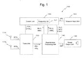
- the schematic structure of a reception device 100 is shown as a block diagram.
- the reception device 100 comprises a main antenna 110 1 that serves as a first antenna means and a sub-antenna 110 2 that serves as a second antenna means.
- this reception device 100 comprises a tuner unit 130 and a reproduction processing unit 140.
- the reception device 100 comprises an actuation input unit 150, a sound output unit 160, and a control unit 190 that serves as a control means.
- the result of reception by the main antenna 110 1 described above is outputted to the tuner unit 130 as a signal RFS 1 .
- the result of reception by the sub-antenna 110 2 described above is outputted to the tuner unit 130 as a signal RFS 2 .
- the tuner unit 130 described above extracts signals on a physical channel to be selected from the signals RFS 1 and RFS 2 and performs tuning processing, and outputs signals IFD 1 and IFD 2 having a predetermined intermediate frequency to the reproduction processing unit 140.
- this tuner unit 130 comprises a main tuner part 131 1 that serves as a first frequency conversion means and a sub-tuner part 131 2 that serves as a second frequency conversion means.
- the main tuner part 131 1 described above performs tuning processing upon the signal RFS 1 from the main antenna 110 1 .
- This main tuner part 131 1 comprises a tuner circuit 132 1 and a local oscillation circuit (OSC) 133 1 .
- OSC local oscillation circuit
- the tuner circuit 132 1 described above extracts a signal from the broadcasting station that is to be tuned to from the signal RFS 1 .
- the result of extraction by the tuner circuit 132 1 is sent to the reproduction processing unit 140 as a signal IFD 1 that has the predetermined intermediate frequency.
- the local oscillation circuit 133 1 described above comprises an oscillator and so on whose frequency of oscillation can be controlled by voltage control or the like. According to a tuning command CSL 1 supplied from the control unit 190, this local oscillation circuit 133 1 generates an oscillation signal CF 1 having a frequency that corresponds to the broadcasting station that is to be tuned to by the main tuner part 131 1 , and supplies this signal to the tuner circuit 132 1 .
- the sub-tuner part 131 2 described above performs tuning processing upon the signal RFS 2 from the sub-antenna 110 2 .
- This sub-tuner part 131 2 comprises a tuner circuit 132 2 and a local oscillation circuit (OSC) 133 2 .
- OSC local oscillation circuit
- the tuner circuit 132 2 described above extracts a signal from the broadcasting station that is to be tuned to from the signal RFS 2 .
- the result of extraction by the tuner circuit 132 2 is sent to the reproduction processing unit 140 as a signal IFD 2 that has the predetermined intermediate frequency.
- the local oscillation circuit 133 2 described above comprises an oscillator and so on whose frequency of oscillation can be controlled by voltage control or the like. According to a tuning command CSL 2 supplied from the control unit 190 independently from the tuning command CSL 1 described above, this local oscillation circuit 133 2 generates an oscillation signal CF 2 having a frequency that corresponds to the broadcasting station that is to be tuned to by the sub-tuner part 131 2 , and supplies this signal to the tuner circuit 132 2 .
- each of the tuner circuits 132 j comprises a mixer (i.e. a mixing device), an intermediate frequency filter (hereinafter also sometimes termed an "IF filter”), and an AD (Analog to Digital) converter (ADC).
- the signals that have passed through the RF filters and the oscillation signals CF j supplied from the local oscillation circuits 133 j are mixed by the mixers. After signal components of an intermediate frequency range determined in advance have been selected by IF filters from the signals that result from mixing by the mixers, they are converted by ADCs into digital signals. The results of these conversions are outputted to the reproduction processing unit 140 as signals IFD j .
- the reproduction processing unit 140 processes the signals IFD 1 and IFD 2 from the tuner unit 130, and generates audio data ADT for supply to the sound output unit 160.
- this reproduction processing unit 140 comprises a filtering processing part 141 that serves as one portion of a generation means, and an audio detection part 142 that serves as another portion of the generation means.
- the reproduction processing unit 140 comprises a muting processing part 143 that serves as a processing means, and a stereo demodulation part 144.
- the reproduction processing unit 140 comprises RDS signal processing parts 145 1 and 145 2 .
- the filtering processing part 141 described above performs filtering processing in order to eliminate distortion in the received signal due to the generation of so called multiple paths.
- the filtering processing part 141 that has this function comprises a filter part 171 1 that serves as a first filtering means and a filter part 171 2 that serves as a second filtering means.
- the filtering processing part 141 comprises a switch part 172 and an addition part 173 that serves as an addition means.
- the filtering processing part 141 also comprises a filtering control part 174 and a filtering control part 175 that serve as filtering control means.
- the filtering processing part 141 comprises a signal selection part 176 and a signal selection part 177.
- the filter part 171 1 described above is constituted by a finite impulse response filter (i.e. an FIR filter).
- This filter part 171 1 performs digital filtering calculation upon the signal IFD 1 from the tuner unit 130 according to filter control information FLC 1 , which is information about a tap coefficient designated by the filtering control part 174, and generates a signal FLD 1 .
- This signal FLD 1 that has thus been generated is outputted to the addition part 173.
- the filter part 171 2 described above is constituted by an FIR filter.
- This filter part 171 2 performs digital filtering calculation upon the signal IFD 2 from the tuner unit 130 according to filter control information FLC 2 , which is information about a tap coefficient designated by the filtering control part 174 or the filtering control part 175, and generates a signal FLD 2 .
- This signal FLD2 that has thus been generated is outputted to the switch part 172, the filtering control part 175, and the signal selection part 177.
- the switch part 172 described above receives the signal FLD 2 from the filter part 171 2 at an A terminal.
- this switch 172 When set to "ON” by a switch control command SLC 1 from the control unit 190, this switch 172 goes into a state in which it is continuous between its A terminal and a B terminal.
- the switch 172 when set to "OFF” by the switch control command SLC 1 from the control unit 190, the switch 172 goes into a state in which it is discontinuous between its A terminal and its B terminal.
- the addition part 173 described above calculates the sum of the signal FLD 1 from the filter part 171 1 and the signal supplied from the switch part 172, and generates a signal ADD.
- This signal ADD that has thus been generated is outputted to the filtering control part 174 and the signal selection part 177.
- the signal from the switch 172 is taken as being a "0" level signal, and the addition operation is performed on that basis.
- the signal ADD becomes the sum of the signals FLD 1 and FLD 2 .
- the signal ADD becomes just the signal FLD 1 .
- the filtering control part 174 described above receives the signal ADD from the addition part 173. And, on the basis of the fact that in principle the amplitude of the FM signal should be constant, according to a CMA (Constant Modulus Algorithm), the filtering control part 174 calculates filter control information FLC 1 specifying filtering operation by the filter part 171 1 and filter control information FLC 21 specifying filtering operation by the filter part 171 2 .
- the filter control information FLC 1 that has thus been calculated is sent to the filter part 171 1 .
- the filter control information FLC 21 that has thus been calculated is sent to the signal selection part 176.
- the filtering control part 174 receives an interrupt control command SPC from the control unit 190.
- the filtering control part 174 interrupts the calculation of the filter control information FLC 1 and FLC 21 , and preserves the values of the filter control information FLC 1 and FLC 21 at that time point.
- the filtering control part 174 resumes the calculation of the filter control information FLC 1 and FLC 21 .
- the filtering control part 175 described above receives the signal FLD 2 from the filter part 171 2 . And, in a similar manner to the filtering control part 174 described above, on the basis of the fact that in principle the amplitude of the FM signal should be constant, and according to a CMA, the filtering control part 175 calculates filter control information FLC 22 specifying filtering operation by the filter part 171 2 . The filter control information FLC 22 that has thus been calculated is sent to the signal selection part 176.
- the signal selection part 176 described above along with receiving the filter control information FLC 21 from the filtering control part 174 at its A terminal, also receives the filter control information FLC 22 from the filtering control part 175 at its B terminal. And, when a command for "select A” is issued from the control unit 190 as a signal selection command SLC 2 , then a state of continuity between the A terminal and a C terminal is established. On the other hand, when a command for "select B" is issued from the control unit 190 as the signal selection command SLC 2 , then a state of continuity between the B terminal and the C terminal is established.
- the filter control information FLC 21 is outputted from the C terminal to the filter part 171 2 as the filter control information FLC 2 .
- the filter control information FLC 22 is outputted from the C terminal to the filter part 171 2 as the filter control information FLC 2 .
- the signal selection part 177 described above along with receiving the signal ADD from the addition part 173 at its A terminal, also receives the signal FLD 2 from the filter part 171 2 at its B terminal. And, when a command for "select A” is issued from the control unit 190 as a signal selection command SLC 3 , then a state of continuity between the A terminal and a C terminal is established. On the other hand, when a command for "select B" is issued from the control unit 190 as a signal selection command SLC 3 , then a state of continuity between the B terminal and the C terminal is established
- the audio detection part 142 described above performs digital wave detection processing upon the signal FPD from the filtering processing part 141 according to a predetermined format, and generates a signal DAD which is a composite signal.
- the signal DAD that has been generated in this manner is outputted to the muting processing part 143.
- the muting processing part 143 described above receives the signal DAD from the audio detection part 142. And the muting processing part 143 performs muting processing or cancels muting processing according to a muting control command MTC from the control unit 190. In other words, when a command for muting processing is issued as the muting control command MTC, then the muting processing part 143 outputs a no-sound signal to the stereo demodulation part 144 as a signal AOD. On the other hand, when a command for muting cancellation is issued as the muting control command MTC, then the muting processing part 143 outputs the signal DAD to the stereo demodulation part 144 as the signal AOD.
- the stereo demodulation part 144 described above performs stereo demodulation processing upon the signal AOD from the muting processing part 143, and generates audio data ADT. This audio data ADT that has thus been generated is outputted to the sound output unit 160.
- the signal AOD is the signal DAD
- reproduction output of the broadcast program emitted from the target station for reproduction is performed by the sound output unit 160.
- the signal AOD is a no-sound signal
- no reproduction output of any sound is performed by the sound output unit 160.
- the RDS signal processing part 145 1 described above receives the signal IFD 1 from the tuner unit 130. And the RDS signal processing part 145 1 detects the reception quality of the broadcast wave from the broadcasting station that is tuned by the above described main tuner part 131 1 in the tuner unit 130, and performs processing of various types upon the data signal that is being used by RDS.
- the RDS signal processing part 145 2 described above receives the signal IFD 2 from the tuner unit 130. And the RDS signal processing part 145 2 detects the reception quality of the broadcast wave from the broadcasting station that is tuned by the above described sub-tuner part 131 2 in the tuner unit 130, and performs processing of various types upon the data signal that is being used by RDS.
- each of the RDS signal processing parts having the function described above comprises a reception level detection part 181 that serves as a j-th detection means.
- each of the RDS signal processing parts 145 j comprises a RDS detection part 182 and a RDS demodulation part 183.
- the reception level detection part 181 described above receives the signal IFD j from the tuner unit 130. And the reception level detection part 181 detects the signal level and the noise level of this signal IFD j . Here, the multi-path noise level is included in the noise level. The result of detection by the reception level detection part 181 is reported to the control unit 190 as reception level information RLV j .
- the RDS detection part 182 described above performs digital wave detection processing upon the signal IFD j from the tuner unit 130 according to a predetermined method, and generates a signal DRD j .
- This signal DRD j that has thus been generated is outputted to the RDS demodulation part 183.
- the RDS demodulation part 183 described above performs demodulation processing upon the signal DRD j from the RDS detection part 182, and generates a data signal DBD j .
- This data signal DBD j includes a program identification code (i.e. a PI code), AF data, which is data about frequency information for alternative candidate stations to the broadcasting station that is tuned to and that belong to the same network as that broadcasting station, and so on.
- This data signal DBD j that has thus been generated is outputted to the control unit 190.
- the actuation input unit 150 is made as a key part provided to the main body portion of the reception device 100, or as a remote input device or the like that includes a key part.
- a touch panel provided to a display unit not shown in the figures as the key part that is provided to the main body portion.
- a structure in which audio input is performed.
- the result of actuation input to the actuation input unit 150 is sent to the control unit 190 as actuation input data IPD.
- the sound output unit 160 comprises: (i) a DA (Digital to Analog) converter that converts audio data ADT received from the reproduction processing unit 140 to an analog signal; (ii) an amplifier that amplifies this analog signal outputted from the DA converter; and (iii) a speaker that converts this amplified analog signal into audio. It should be understood that (i) to (iii) are provided for each of the stereo signals that are the result of stereo demodulation processing.
- DA Digital to Analog
- control unit 190 controls the overall operation of the reception device 100.
- this control unit 190 comprises a CPU (Central Processing Unit) and a storage device and so on, and controls the overall operation of the reception device 100 by executing a program that is prepared in advance.
- CPU Central Processing Unit
- F k frequency information
- RQ k reception quality information
- CP k changeover level priority information
- control unit 190 there is included control during reproduction of the program broadcast from the target station for reproduction by the reception device 100 in a combined reproduction mode or in a single reproduction mode shown in Fig. 7 .
- combined reproduction mode is a mode in which reproduction output is performed on the basis of the result of reception of the broadcast wave from the target station for reproduction by both the main antenna 110 1 and the sub-antenna 110 2 .
- single reproduction mode is a mode in which reproduction output is performed on the basis of the result of reception of the broadcast wave from the target station for reproduction by only the main antenna 110 1 .
- control by the control unit 190 also includes transition control between the combined reproduction mode and the single reproduction mode, on the basis of the reception quality of the broadcast wave from the target station for reproduction at the main antenna 110 1 . And this control by the control unit 190 also includes control for changing over the tuning from the current target station for reproduction to a new target station for reproduction.
- control unit 190 The details of the control operation of the control unit 190 described above will be described hereinafter.
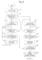
- a reproduction control procedure for the program broadcast from the target station for reproduction is started by the control unit 190.
- initial processing is performed in a step S11.
- control unit 190 issues a command for muting processing to the muting processing part 143.
- control unit 190 issues a command to the filtering control part 174 for cancellation of interruption of filter control.
- control unit 190 issues a command to the main tuner part 131 1 to tune to the target station for reproduction.
- the control unit 190 specifies the instantaneous signal level and noise level at this time point on the basis of the reception level information RLV 1 from the RDS signal processing part 145 1 . And the control unit 190 makes the decision as to whether or not the reception quality is satisfactory on the basis of the signal level and the noise level that have thus been specified.
- the algorithm for deciding whether or not the reception quality is satisfactory is determined in advance on the basis of experiment, simulation, experience and so on. Generally, in this algorithm, it is arranged to decide that the reception quality is satisfactory if the signal level is higher than some level, and moreover the noise level is sufficiently lower than the signal level.
- step S12 But if the result of the decision in the step S12 is negative (N in the step S12), then the flow of control is transferred to a step S17. It should be understood that the processing of the step S17 and subsequently will be described hereinafter.
- step S12 If the result of the decision in the step S12 is affirmative (Y in the step S12), then the flow of control proceeds to a step S13. In this step S13, a setting for the single reproduction mode is performed.
- the control unit 190 issues an "OFF" command for the switch part 172, and also issues a "select A" command to the signal selection part 177. And, after a time period in which filter control by the filtering control part 174 is considered to be adequate has elapsed, the control unit 190 issues a command for eliminating muting to the muting processing part 143. As a result the operation of the single reproduction mode is started, in which reproduction output is performed on the basis of the result of reception of the broadcast wave from the target station for reproduction by only the main antenna 110 1 .
- the processing in this step S14 is performed in a similar manner to the case of the step S12 described above. If the result of the decision in the step S14 is negative (N in the step S14), then the flow of control is transferred to a step S 17, after a command for muting processing has been issued to the muting processing part 143 by the control unit 190. It should be understood that, when the flow of control is transferred to the step S17, the operation of the single reproduction mode comes to an end.
- step S15 after seek processing which will be described hereinafter has been performed, a decision is made as to whether or not a first predetermined time period has elapsed. And if the result of this decision is negative (N in the step S15), then the flow of control returns to the step S14.
- this first predetermined time period is determined in advance from the standpoint of implementing effective and quick seek processing, on the basis of experiment, simulation, experience and so on.
- step S15 seek processing is performed during the operation of the single reproduction mode.
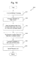
- step S31 the control unit 190 issues a command to the sub-tuner part 131 2 to tune to an alternative candidate station for which the reception quality is to be detected in this episode of seek processing.
- the signal level and the noise level of the broadcast wave from that alternative candidate station received by the sub-antenna 110 2 are detected by the RDS signal processing part 145 2 .
- the result of detection is reported to the control unit 190 as reception level information RLV 2 .
- the control unit 190 gets the reception level information RLV 2 from the RDS signal processing part 145 2 . And the signal level and the noise level of the broadcast wave from the alternative candidate station at this time point are specified on the basis of this reception level information RLV 2 that has been acquired.
- the control unit 190 updates the frequency list FLT on the basis of the signal level and the noise level that have thus been specified. During this updating, the control unit 190 registers the signal level and the noise level specified in this seek episode as the reception quality information (RQ k0 ) corresponding to this alternative candidate station (PC k0 ). Moreover, the control unit 190 evaluates the reception quality from the signal level and the noise level specified in this seek episode, and updates the changeover priority level information (CP k ) correlated with each of the alternative candidate stations (PC k ).
- step S17 When the flow of control proceeds to the step S17 from the step S12 or the step S14 described above, setting for the combined reproduction mode is performed.
- the control unit 190 issues a command to the switch part 172 to go to "ON", and also issues a command to the signal selection part 177 to "select A”.
- the control unit 190 issues a command to the main tuner part 131 1 to tune to the target station for reproduction.
- the control unit 190 issues a command to the muting processing part 143 to cancel muting.
- the operation of the combined reproduction mode starts, in which reproduction output is performed on the basis of the results of reception of the broadcast wave from the target station for reproduction by both the main antenna 110 1 and the sub-antenna 110 2 .
- the processing in this step S18 is performed in a manner similar to that in the step S12 described above. If the result of the decision in the step S18 is affirmative (Y in the step S18) then, after a command has been issued by the control unit 190 to the muting processing part 143 for muting processing, the flow of control proceeds to the step S13. Subsequently, the processing of the steps S13 through S16 is performed. It should be understood that, when the flow of control proceeds to the step S13, the operation of the combined reproduction mode comes to an end.
- step S 18 If the result of the decision in the step S 18 is negative (N in the step S18), then the flow of control proceeds to a step S19.
- step S19 after the seek processing of the step S16 described above or seek processing of a step S20 that will be described hereinafter has been executed, a decision is made as to whether or not a second predetermined time period has elapsed. If the result of this decision is negative (N in the step S19), then the flow of control returns to the step S18.
- this second predetermined time period is determined in advance on the basis of experiment, simulation, experience and so on, from the standpoint of preventing the generation of any feeling of discomfort to the user, and moreover of implementing effective and quick seek processing.
- step S 19 If the result of the decision in the step S 19 is affirmative (Y in the step S 19), then the flow of control proceeds to a step S20.
- step S20 seek processing is performed during the operation of the combined reproduction mode.
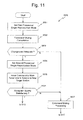
- step S41 the control unit 190 issues a command to the muting processing part 143 to perform muting processing.
- the control unit 190 issues a command to the filtering control part 174 to interrupt filter control.
- control unit 190 issues commands to the main tuner part 131 1 and the sub-tuner part 131 2 to tune to two alternative candidate stations for which the reception quality is to be detected in this episode of seek processing.
- the control unit 190 is adapted to select these two alternative candidate stations, during these tuning commands, according to the order of changeover priority level information (CP k ) in the frequency list FLT.
- the signal level and the noise level of the broadcast wave from one of the alternative candidate stations received by the main antenna 110 1 are detected by the RDS signal processing part 145 1 . And the result of this detection is reported to the control unit 190 as the reception level information RLV 1 .
- the signal level and the noise level of the broadcast wave from the other one of the alternative candidate stations received by the sub-antenna 110 2 are detected by the RDS signal processing part 145 2 . And the result of this detection is reported to the control unit 190 as the reception level information RLV 2.
- the control unit 190 gets the reception level information RLV 1 from the RDS signal processing part 145 1 and the reception level information RLV 2 from the RDS signal processing part 145 2 . And, along with specifying the signal level and the noise level of the broadcast wave from the one alternative candidate station at this time point on the basis of the reception level information RLV 1 that has been obtained, also it specifies the signal level and the noise level of the broadcast wave from the other alternative candidate station at this time point on the basis of the reception level information RLV 2 that has been obtained.
- a step S45 the control unit 190 issues a command to the filtering control part 174 for cancellation of the interruption of filter control.
- the filtering control part 174 resumes the calculation of new filter control information FLC 1 and FLC 21 while taking the values of the filter control information FLC 1 and FLC 21 at the time point that the step S42 was executed as departure values. Due to this, the time period until filter control comes to be adequate comes to be shortened.
- control unit 190 updates the frequency list FLT on the basis of the signal levels and the noise levels that have been specified for these two alternative candidate stations. This updating of the frequency list FLT is performed in a similar manner to the case in the step S33 described above.
- step S21 On the basis of the instantaneous signal levels and noise levels related to the two alternative candidate stations specified in the step S20, and on the basis of the instantaneous signal level and noise level of the target station for reproduction detected directly before the processing of the step S20, the control unit 190 makes a decision as to whether or not there exists any changeover candidate station among these two alternative candidate stations, for which there is a possibility that it can be made an adequate new target station for reproduction. This decision is performed by making a decision as to whether or not the instantaneous reception quality of the broadcast wave from at least one of these two alternative candidate stations is higher than the instantaneous reception quality of the broadcast wave from the target station for reproduction.
- step S21 If the result of the decision in the step S21 is negative (N in the step S21), then the flow of control returns to the step S17. And the processing of the steps S17 through S21 described above is performed until the result of the decision in the step S18 becomes affirmative, or the result of the decision in the step S21 becomes affirmative.
- step S21 If the result of the decision in the step S21 is affirmative (Y in the step S21), then the flow of control proceeds to a step S22.
- step S22 processing is performed relating to the changeover from the current target station for reproduction to the new target station for reproduction.
- This first provisional single reproduction mode is a mode in which, provisionally in order to continue reproduction output, reproduction output is performed on the basis of the result of reception of the broadcast wave from the target station for reproduction by only the main antenna 110 1 , irrespective of whether the reception quality of the broadcast wave from the target station for reproduction is satisfactory or not.
- the control unit 190 issues an "OFF" command to the switch part 172, and also issues a "select B" command to the signal selection part 176.
- the control unit 190 issues a command to the main tuner part 131 1 to tune to the target station for reproduction.
- the wave detection result based upon the result of reception of the broadcast wave from the target station for reproduction by only the main antenna 110 1 is sent to the muting processing part 143.
- filter control for the filter part 171 2 is performed by the filtering control part 175.
- step S52 After a time period has elapsed in which it is considered that filter control by the filtering control part 174 will become adequate, the control unit 190 issues a command to the muting processing part 143 to cancel muting. As a result, reproduction output is performed on the basis of the result of reception of the broadcast wave from the target station for reproduction by only the main antenna 110 1.
- the control unit 190 first issues a command to the sub-tuner part 131 2 to tune to the changeover candidate station.
- the control unit 190 makes a decision as to whether or not the changeover of the target station for reproduction is adequate, by making a decision as to whether or not changeover conditions are satisfied, such as whether the PI data from the target station for reproduction is the same as the PI data from the changeover candidate station, whether the average reception quality from the changeover candidate station during a predetermined time interval is higher than the average reception quality of the broadcast wave from the target station for reproduction over that predetermined time interval, and the like.
- this predetermined time interval is determined in advance on the basis of experiment, simulation, experience and the like, from the standpoint of accuracy and speed of deciding upon the adequacy of the changeover.
- step S53 If the result of the decision in the step S53 is negative (N in the step S53), then the flow of control is transferred to a step S57.
- step S57 the control unit 190 issues a command to the muting processing part 143 to perform muting processing. Subsequently the flow of control is transferred to the step S17 of Fig. 8 .
- the operation of the combined reproduction mode is resumed, in which reproduction output is performed on the basis of the results of reception of the broadcast wave from the target station for reproduction by the main antenna 110 1 and the sub-antenna 110 2 .
- step S53 if the result of the decision in the step S53 is affirmative (Y in the step S53), then the changeover candidate station up till now is confirmed as the new target station for reproduction. And then the flow of control proceeds to a step S54.
- This second provisional single reproduction mode is a mode in which, provisionally in order to continue reproduction output, reproduction output is performed on the basis of the result of reception of the broadcast wave from the target station for reproduction by only the sub-antenna 110 2 .
- control unit 190 issues a "select B" command to the signal selection part 177.
- reproduction output is performed on the basis of the result of reception of the broadcast wave from the new target station for reproduction by only the sub-antenna 110 2 .
- a step S55 the control unit 190 issues a command to the main tuner part 131 1 to tune in to the new target station for reproduction.
- the result of filtering processing upon the result of reception of the broadcast wave from the new target station for reproduction by only the main antenna 110 1 is sent to the A terminal of the signal selection part 177.
- the signal level and the noise level of the broadcast wave from the new target station for reproduction received by the main antenna 110 1 are detected by the RDS signal processing part 145 1 . And the result of this detection is reported to the control unit 190 as the reception level information RLV 1 .
- step S56 If the result of the decision in the step S56 is negative (N in the step S56), then the flow of control proceeds to the step S57. And in this step S57, after a command for muting processing has been issued by the control unit 190 to the muting processing part 143, the flow of control is transferred to the step S17 of Fig. 8 . As a result the operation of the combined reproduction mode is resumed, in which reproduction output is performed on the basis of the results of reception of the broadcast wave from the target station for reproduction by the main antenna 110 1 and the sub-antenna 110 2 .
- step S56 if the result of the decision in the step S56 is affirmative (Y in the step S56), then the flow of control is transferred to the step S13 of Fig. 8 .
- the operation of the single reproduction mode is started, in which reproduction output is performed on the basis of the result of reception of the broadcast wave from the target station for reproduction by only the main antenna 110 1.
- phase diversity combination operation condition that the reception quality of the broadcast wave from the target station for reproduction is lower than a predetermined reception quality is satisfied, then operation is performed in the combined reproduction mode, in which reproduction output is performed on the basis of the results of reception of the broadcast wave from the target station for reproduction by both the main antenna 110 1 and the sub-antenna 110 2 . And periodically, during this combined reproduction mode, a command for muting processing is issued for a predetermined time period, this being a command for preventing noise reproduction.
- the control unit 190 issues commands for tuning to mutually different broadcasting stations among the alterative candidate stations, according to the frequency list FLT. As a result, detection of reception quality is performed in parallel for the broadcast wave from each of these two alternative candidate stations.
- a command for interruption of filter control is issued to the filtering control part 174, and the filter control information at the time point of this interruption is stored. Due to this, when resuming the previous operation of the combined reproduction mode for the target station for reproduction, it is possible rapidly to shorten the time period until filter control by the filtering control part 174 is performed adequately, without performing changeover of the target station for reproduction after the seek operation.
- reproduction output is performed on the basis of the result of reception of the broadcast wave from the new target station for reproduction by only the sub-antenna 110 2 .
- setting of the combined reproduction mode or of the single reproduction mode is performed on the basis of the reception quality of the broadcast wave from the new target station for reproduction. Due to this, it is possible to prevent long term interruption of the reproduction output when changing over to the new target station for reproduction.
- muting processing was employed as noise reproduction prevention processing
- hold processing in which the reproduction output signal level is held at the time point that noise reproduction prevention processing is started.
- a FIR filter was employed as the filter part, it would also be possible to employ an infinite impulse response filter (i.e. an IIR filter).
- the frequency list FLT was constructed using the RDS method, if it is possible to use another method that can specify groups of physical channels upon which the same broadcast contents are broadcast, it would also be acceptable to construct the frequency list FLT by using that other method.
- the multi-path noise level as a noise level
- the present invention was applied to an FM radio reception device that was mounted to a vehicle, it would also be possible to apply the present invention to a device having another type of reception capability; and it would also be possible to apply the present invention to a reception device that is mounted to a moving body other than a vehicle. Furthermore it would also be possible to apply the present invention to a device having a broadcast reception function and that is installed in, for example, a household or the like.
- control unit 190 it is arranged for the control unit 190 to execute the control procedures of the embodiment described above by being built as a computer that includes a CPU and by a program that is prepared in advance being executed by that computer, it would also be acceptable to arrange to constitute all or a part of the control unit 190 as hardware such as a dedicated LSI.
- control unit 190 it would also be acceptable to arrange for the program that is executed by the control unit 190 to be acquired in a format in which it is recorded upon a transportable recording medium such as a CD-ROM or a DVD or the like; and it would also be acceptable to arrange for it to be acquired in a format in which it is distributed via a network such as the internet or the like.
Landscapes
- Engineering & Computer Science (AREA)
- Signal Processing (AREA)
- Radio Transmission System (AREA)
- Circuits Of Receivers In General (AREA)
Applications Claiming Priority (1)
| Application Number | Priority Date | Filing Date | Title |
|---|---|---|---|
| PCT/JP2008/071450 WO2010061439A1 (fr) | 2008-11-26 | 2008-11-26 | Dispositif de réception, procédé de traitement de réception, programme de traitement de réception et support d'enregistrement |
Publications (2)
| Publication Number | Publication Date |
|---|---|
| EP2372926A1 true EP2372926A1 (fr) | 2011-10-05 |
| EP2372926A4 EP2372926A4 (fr) | 2012-06-20 |
Family
ID=42225332
Family Applications (1)
| Application Number | Title | Priority Date | Filing Date |
|---|---|---|---|
| EP08878396A Withdrawn EP2372926A4 (fr) | 2008-11-26 | 2008-11-26 | Dispositif de réception, procédé de traitement de réception, programme de traitement de réception et support d'enregistrement |
Country Status (3)
| Country | Link |
|---|---|
| EP (1) | EP2372926A4 (fr) |
| JP (1) | JP5033924B2 (fr) |
| WO (1) | WO2010061439A1 (fr) |
Cited By (4)
| Publication number | Priority date | Publication date | Assignee | Title |
|---|---|---|---|---|
| JP2014127851A (ja) * | 2012-12-26 | 2014-07-07 | Pioneer Electronic Corp | 放送受信装置及び放送受信方法 |
| CN104144010A (zh) * | 2013-05-08 | 2014-11-12 | Nxp股份有限公司 | 在无线数据传输环境中管理无线传输的使用数据 |
| EP3174226A1 (fr) * | 2015-11-26 | 2017-05-31 | Alpine Electronics, Inc. | Dispositif de réception de radiodiffusion et procédé de commande de réception de diffusion |
| CN110888134A (zh) * | 2019-11-04 | 2020-03-17 | 电子科技大学 | 一种非协作和协作一体化机场场面监视系统 |
Families Citing this family (1)
| Publication number | Priority date | Publication date | Assignee | Title |
|---|---|---|---|---|
| JP2016187084A (ja) * | 2015-03-27 | 2016-10-27 | パイオニア株式会社 | 放送受信装置及び放送受信方法 |
Family Cites Families (6)
| Publication number | Priority date | Publication date | Assignee | Title |
|---|---|---|---|---|
| JP2568024Y2 (ja) * | 1992-04-27 | 1998-04-08 | 株式会社ケンウッド | ツインチューナラジオデータシステム受信機 |
| JP4545534B2 (ja) * | 2004-09-16 | 2010-09-15 | 三菱電機株式会社 | 無線受信装置 |
| JP2006303664A (ja) * | 2005-04-18 | 2006-11-02 | Matsushita Electric Ind Co Ltd | 受信装置及び集積回路 |
| JP4614906B2 (ja) * | 2005-07-26 | 2011-01-19 | アルパイン株式会社 | 受信装置 |
| JP2007288631A (ja) * | 2006-04-19 | 2007-11-01 | Sony Corp | ダイバーシティ受信機 |
| JP2008085754A (ja) * | 2006-09-28 | 2008-04-10 | Clarion Co Ltd | デジタル放送受信装置、並びにデジタル放送受信装置の制御方法及び制御プログラム。 |
-
2008
- 2008-11-26 JP JP2010540247A patent/JP5033924B2/ja not_active Expired - Fee Related
- 2008-11-26 WO PCT/JP2008/071450 patent/WO2010061439A1/fr not_active Ceased
- 2008-11-26 EP EP08878396A patent/EP2372926A4/fr not_active Withdrawn
Cited By (6)
| Publication number | Priority date | Publication date | Assignee | Title |
|---|---|---|---|---|
| JP2014127851A (ja) * | 2012-12-26 | 2014-07-07 | Pioneer Electronic Corp | 放送受信装置及び放送受信方法 |
| CN104144010A (zh) * | 2013-05-08 | 2014-11-12 | Nxp股份有限公司 | 在无线数据传输环境中管理无线传输的使用数据 |
| EP2802088A1 (fr) * | 2013-05-08 | 2014-11-12 | Nxp B.V. | Gestion des données d'utilisation transmises sans fil dans un environnement de transmission de données sans fil |
| US9941949B2 (en) | 2013-05-08 | 2018-04-10 | Nxp B.V. | Managing wirelessly transmitted use-data in a wireless data transmission environment |
| EP3174226A1 (fr) * | 2015-11-26 | 2017-05-31 | Alpine Electronics, Inc. | Dispositif de réception de radiodiffusion et procédé de commande de réception de diffusion |
| CN110888134A (zh) * | 2019-11-04 | 2020-03-17 | 电子科技大学 | 一种非协作和协作一体化机场场面监视系统 |
Also Published As
| Publication number | Publication date |
|---|---|
| JPWO2010061439A1 (ja) | 2012-04-19 |
| JP5033924B2 (ja) | 2012-09-26 |
| WO2010061439A1 (fr) | 2010-06-03 |
| EP2372926A4 (fr) | 2012-06-20 |
Similar Documents
| Publication | Publication Date | Title |
|---|---|---|
| JP5033924B2 (ja) | 受信装置、受信処理方法、受信処理プログラム及び記録媒体 | |
| JP4614906B2 (ja) | 受信装置 | |
| US7577410B2 (en) | Audio apparatus | |
| US8483635B2 (en) | Broadcast receiving apparatus and radio receiving apparatus | |
| JP2010136183A (ja) | ラジオ受信装置 | |
| US8103230B2 (en) | Broadcasting receiver, broadcasting identification method, broadcasting identification program, and recording medium therefor | |
| JP5061885B2 (ja) | ダイバーシティ受信装置及びダイバーシティ制御方法 | |
| JP4361089B2 (ja) | 位相合成ダイバーシティ受信機 | |
| JP4173171B2 (ja) | ラジオ受信機及び搬送波検出方法 | |
| JP2005347810A (ja) | 隣接妨害検出装置及び隣接妨害除去装置ならびに受信装置 | |
| JP2016134645A (ja) | 放送受信装置及び放送受信方法 | |
| JP4378263B2 (ja) | 受信装置 | |
| JP7054751B2 (ja) | 放送受信装置及び放送受信方法 | |
| JP2005198092A (ja) | 受信機 | |
| JP4851987B2 (ja) | 放送受信装置、選局方法、選局プログラム及びその記録媒体 | |
| JP2009049954A (ja) | 受信装置および受信方法 | |
| WO2013076801A1 (fr) | Dispositif de correction de signal audio et procédé de correction de signal audio | |
| JP6257894B2 (ja) | 放送受信装置及び放送受信方法 | |
| JP6144909B2 (ja) | 放送受信装置及び放送受信方法 | |
| JP4627094B2 (ja) | ダイバーシティ受信機 | |
| JP2020010373A (ja) | 放送受信装置及び放送受信方法 | |
| JP4312652B2 (ja) | ラジオ受信機 | |
| JP2005184534A (ja) | 受信装置、チューナおよびチューナ管理装置 | |
| JP2004023137A (ja) | 受信装置、その方法、そのプログラム、そのプログラムを記録した記録媒体、および、通信システム | |
| JP2018042287A (ja) | 放送受信装置及び放送受信方法 |
Legal Events
| Date | Code | Title | Description |
|---|---|---|---|
| PUAI | Public reference made under article 153(3) epc to a published international application that has entered the european phase |
Free format text: ORIGINAL CODE: 0009012 |
|
| 17P | Request for examination filed |
Effective date: 20110608 |
|
| AK | Designated contracting states |
Kind code of ref document: A1 Designated state(s): AT BE BG CH CY CZ DE DK EE ES FI FR GB GR HR HU IE IS IT LI LT LU LV MC MT NL NO PL PT RO SE SI SK TR |
|
| DAX | Request for extension of the european patent (deleted) | ||
| A4 | Supplementary search report drawn up and despatched |
Effective date: 20120521 |
|
| RIC1 | Information provided on ipc code assigned before grant |
Ipc: H04B 7/08 20060101AFI20120514BHEP Ipc: H04B 1/16 20060101ALI20120514BHEP |
|
| STAA | Information on the status of an ep patent application or granted ep patent |
Free format text: STATUS: THE APPLICATION IS DEEMED TO BE WITHDRAWN |
|
| 18D | Application deemed to be withdrawn |
Effective date: 20121219 |