EP2373063B1 - Dispositif auditif et procédé de réglage de celui-ci pour un fonctionnement sans contre-réaction - Google Patents
Dispositif auditif et procédé de réglage de celui-ci pour un fonctionnement sans contre-réaction Download PDFInfo
- Publication number
- EP2373063B1 EP2373063B1 EP11154523A EP11154523A EP2373063B1 EP 2373063 B1 EP2373063 B1 EP 2373063B1 EP 11154523 A EP11154523 A EP 11154523A EP 11154523 A EP11154523 A EP 11154523A EP 2373063 B1 EP2373063 B1 EP 2373063B1
- Authority
- EP
- European Patent Office
- Prior art keywords
- feedback
- parameter
- directional
- hearing device
- hearing
- Prior art date
- Legal status (The legal status is an assumption and is not a legal conclusion. Google has not performed a legal analysis and makes no representation as to the accuracy of the status listed.)
- Active
Links
Images


Classifications
-
- H—ELECTRICITY
- H04—ELECTRIC COMMUNICATION TECHNIQUE
- H04R—LOUDSPEAKERS, MICROPHONES, GRAMOPHONE PICK-UPS OR LIKE ACOUSTIC ELECTROMECHANICAL TRANSDUCERS; ELECTRIC HEARING AIDS; PUBLIC ADDRESS SYSTEMS
- H04R25/00—Electric hearing aids
-
- H—ELECTRICITY
- H04—ELECTRIC COMMUNICATION TECHNIQUE
- H04R—LOUDSPEAKERS, MICROPHONES, GRAMOPHONE PICK-UPS OR LIKE ACOUSTIC ELECTROMECHANICAL TRANSDUCERS; ELECTRIC HEARING AIDS; PUBLIC ADDRESS SYSTEMS
- H04R25/00—Electric hearing aids
- H04R25/45—Prevention of acoustic reaction, i.e. acoustic oscillatory feedback
- H04R25/453—Prevention of acoustic reaction, i.e. acoustic oscillatory feedback electronically
-
- H—ELECTRICITY
- H04—ELECTRIC COMMUNICATION TECHNIQUE
- H04R—LOUDSPEAKERS, MICROPHONES, GRAMOPHONE PICK-UPS OR LIKE ACOUSTIC ELECTROMECHANICAL TRANSDUCERS; ELECTRIC HEARING AIDS; PUBLIC ADDRESS SYSTEMS
- H04R2225/00—Details of deaf aids covered by H04R25/00, not provided for in any of its subgroups
- H04R2225/49—Reducing the effects of electromagnetic noise on the functioning of hearing aids, by, e.g. shielding, signal processing adaptation, selective (de)activation of electronic parts in hearing aid
-
- H—ELECTRICITY
- H04—ELECTRIC COMMUNICATION TECHNIQUE
- H04R—LOUDSPEAKERS, MICROPHONES, GRAMOPHONE PICK-UPS OR LIKE ACOUSTIC ELECTROMECHANICAL TRANSDUCERS; ELECTRIC HEARING AIDS; PUBLIC ADDRESS SYSTEMS
- H04R25/00—Electric hearing aids
- H04R25/40—Arrangements for obtaining a desired directivity characteristic
- H04R25/407—Circuits for combining signals of a plurality of transducers
Definitions
- the invention relates to a method for adjusting a hearing device in order to enable a feedback-reduced operation of the hearing device.
- the invention also relates to a hearing device in which such a feedback reduced operation can be made possible.
- at least one directional parameter for defining a directional characteristic of a microphone arrangement of the hearing device can be set.
- hearing device is understood in particular to mean a hearing device.
- the term includes other portable acoustic devices such as headsets, headphones and the like.
- Hearing aids are portable hearing aids that are used to care for the hearing impaired.
- different types of hearing aids such as behind-the-ear hearing aids (BTE), hearing aid with external receiver (RIC: receiver in the canal) and in-the-ear hearing aids (IDO), e.g. Concha hearing aids or canal hearing aids (ITE, CIC).
- BTE behind-the-ear hearing aids
- RIC hearing aid with external receiver
- IDO in-the-ear hearing aids
- ITE canal hearing aids
- the hearing aids listed by way of example are worn on the outer ear or in the ear canal.
- bone conduction hearing aids, implantable or vibrotactile hearing aids are also available on the market. The stimulation of the damaged hearing takes place either mechanically or electrically.
- Hearing aids have in principle as essential components an input transducer, an amplifier and an output transducer.
- the input transducer is usually a sound receiver, z. As a microphone, and / or an electromagnetic receiver, for. B. an induction coil.
- the output transducer is usually used as an electroacoustic transducer, z. As miniature speaker, or as an electromechanical transducer, z. B. bone conduction, realized.
- the amplifier is standard integrated into a signal processing unit. This basic structure is in FIG. 1 shown using the example of a behind-the-ear hearing aid. In a hearing aid housing 1 for carrying behind the ear, one or more microphones 2 for receiving the sound from the environment are installed.
- a signal processing unit 3 which is also integrated in the hearing aid housing 1, processes the microphone signals and amplifies them.
- the output signal of the signal processing unit 3 is transmitted to a loudspeaker or earpiece 4, which outputs an acoustic signal.
- the sound is optionally transmitted via a sound tube, which is fixed with an earmold in the ear canal, to the eardrum of the device carrier.
- the power supply of the hearing device and in particular the signal processing unit 3 is effected by a likewise integrated into the hearing aid housing 1 battery. 5
- a hearing device in particular a hearing aid, it may happen that the sound generated by the listener passes out of the ear canal of the device wearer and back to a microphone of the hearing device.
- a passage opening for aerating the auditory canal a so-called vent
- a feedback path may also pass through portions of the skull of the implement carrier if these areas are e.g. be excited by the sound waves of the listener to vibrations and the sound signal propagates as structure-borne noise.
- the listener already produces a structure-borne noise, which may be fed back under certain circumstances.
- the sound signal of the listener If the sound signal of the listener is detected by a microphone, it can be amplified in the hearing device and back from the listener be radiated. In such a case, the acoustic feedback path and the signal processing of the hearing aid together constitute a feedback loop. In the context of illustrating the invention, the transmission of a signal along a feedback loop is referred to as a feedback effect.
- the feedback effect is critical when there is an overall gain in the feedback loop greater than unity. If, for example, an earmold of the hearing device has not been inserted into the auditory canal in the intended manner, so that an air gap remains between the earmold and the skin of the device wearer, a feedback path may result, which leads mainly through this gap. An attenuation of the feedback sound is then particularly low. At the microphone, the fed-back sound has a correspondingly high volume. If the received microphone signal is then amplified and converted again into a sound by the listener, this can lead to the listener producing an ever louder sound.
- a feedback loop having a gain greater than one may result in self-excitation of the hearing device resulting in a whistling sound referred to as feedback or feedback in the context of the illustration of the invention.
- a whistling sound is usually disturbed by the equipment wearer and by persons in his vicinity.
- the probability of a feedback increases, in particular, when the microphone unit signals are amplified very strongly in some frequency ranges by the signal processing unit of the hearing device in order to compensate for a hearing loss of the equipment wearer.
- a gain that triggers feedback also means critical amplification.
- the directional characteristic describes how strongly a sound signal is attenuated by the signal processing of the hearing device as a function of which direction the sound strikes the hearing device. If it is found that a sound fed back from the listener from one direction strikes the microphones, for which a particularly strong attenuation results according to the directional characteristic, this may possibly prevent feedback. If, on the other hand, a feedback sound from one direction reaches the microphones, for which, according to the directional characteristic, a particularly low attenuation results, this can even encourage feedback.
- the directional characteristic can be set by means of a directional parameter. Then, in the hearing apparatus, it may be possible to control the value of the directional parameter, for example, depending on environmental parameters, so that in different situations, e.g. in a conversation or during a concert, in each case a directional characteristic is provided by which a device carrier can perceive its environment particularly well.
- a method and a hearing aid with a directional microphone system which has at least two microphones. By weighting the microphone signals in different frequency bands, a direction-dependent sensitivity of the directional microphone is determined. With the method, at least one acoustic interference signal can thus be effectively suppressed.
- a hearing aid device which compensates for acoustic and electromagnetic feedback signals by means of an adaptive compensation device.
- the hearing aid device in this case has a weighting device with which the signal of the microphone and / or the electromagnetic receiver is weighted.
- a hearing aid which has both a multi-microphone arrangement with a processing unit for generating a directional characteristic and a unit for feedback suppression.
- a step size of the feedback suppression is always changed in the hearing device when a directional parameter is within a medium interval between the two possible extreme values 0 and 1. This is to be preempted possible feedback whistles.
- the feedback suppression unit is capable of attenuating an actually occurring feedback whistle with the aid of a tone detector. These are parameters of a FIR filter the feedback suppression unit changed until the whistle disappears.
- the object of the present invention is to enable a hearing device in which a directional characteristic of a microphone arrangement depends on a value of a directional parameter, a feedback-reduced operation of the hearing device.
- the object is achieved by a method according to claim 1.
- the object is also achieved by a method according to claim 6 and by a hearing device according to claim 7.
- Advantageous developments of the method according to the invention and the hearing device according to the invention are given by the subclaims.
- a hearing device By means of the method according to the invention, a hearing device can be operated.
- the first of these procedures concerns while a hearing device with a microphone arrangement, in which a directional parameter for setting a directional characteristic of the microphone arrangement is adjustable.
- Such adjustable microphone arrangements are known in principle from the prior art in many embodiments.
- a stability condition for a feedback-reduced operation of the hearing device is specified.
- a stability condition can for example be based on a calculation rule by means of which it can be determined whether the system is stable in the sense described above. It is always given a stability condition in which it depends on the value of the directional parameter, whether it is satisfied or not. Based on the stability condition, those values of the directional parameter for which the stability condition is fulfilled are then determined according to the method. In a further step, the values for the directional parameter which are possible during operation of the hearing device are then limited to the determined values. In other words, such settings of the directional characteristic are prevented, by which a feedback is favored. This is achieved by the exclusive admission of the determined values.
- Which of the permitted values is actually set can thereby be determined by another method.
- Such a method may be, for example, the already mentioned method for optimizing the directional characteristic as a function of environmental parameters.
- a stability condition may be that an overall gain resulting from one sweep of a feedback loop is less than one.
- the overall gain is a dependent on the directional characteristic of the microphone array size. That the overall gain is less than one, but need not always be the condition for a stable, so essentially feedback-free, operation. If, for example, an algorithm for feedback suppression is also provided in the hearing device, then a stability condition can be that only such feedback is prevented, which can no longer be suppressed by the algorithm in a time period acceptable to the device carrier.
- the overall gain of the feedback loop must be significantly less than unity. This can be useful, for example, if changes in the transfer function are to be expected and also for such changed transfer functions a substantially feedback-free operation should still be guaranteed.
- a transfer function can change, for example, in that the hearing device slips on an ear of the device carrier.
- a stability condition can also include the criterion that a measured value of a physical variable or a value of a control parameter lies within a correspondingly predetermined interval.
- a term of a denominator of a total transfer function is specified, the term comprising at least the directional parameter and a transfer function of a feedback path. Those values are determined for the directional parameter for which the stability condition is satisfied, that the term fulfills a predetermined criterion. The term preferably determines a position of one pole of the total transfer function in the complex number plane.
- the overall transfer function also includes a transfer function of a feedback path. This also becomes an influence of an environment the hearing device on the feedback behavior taken into account. Since the total transfer function also includes the directivity parameter itself, an analytical calculation of the stability value or an interval of stability values is advantageously possible. Preferably, a corresponding transfer function is determined for each microphone.
- the method according to the invention is also advantageously developed if the values are determined as a function of a frequency of a signal. Then, for example, different stability values can be provided for individual channels of a filter bank. As a result, a different stability condition can be specified for each channel, without having to unnecessarily restrict a directional characteristic in another channel in order to fulfill a stability condition in one channel.
- the overall transfer function A / B allows, for the first time, an analytical calculation of values for stable operation.
- the directional parameter here is preferably the weighting factor a.
- the development of the first method according to the invention is based on the knowledge that a feedback-reduced or substantially feedback-free operation is often possible for entire intervals a ⁇ a 0 . Accordingly, then only the limit a 0 of the interval must be determined in an advantageous manner. For each value from this interval, there is the certainty that a feedback reduced operation is possible.
- By accurately calculating values for the weighting factor it is advantageously ensured that a predetermined stability condition is maintained and yet the weighting factor is not unnecessarily severely restricted.
- a measure of a strength of the feedback effect can be provided by the term. This measure allows, for example, to determine how robust the hearing device is for a given value of the weighting factor a against feedback. A hearing device is all the more robust, the more the transfer function F 1 and F 2 and other variables contained in the term can change, without this leading to an unforeseen feedback comes. As the stability limit, the value of one is preferably used.
- the second method according to the invention relates to the operation of a hearing device in which a directional parameter for determining a directional characteristic of a microphone arrangement can be set as a first parameter and a control parameter for controlling a device for feedback suppression as a second parameter.
- the method provides a measure of a feedback effect.
- An example of such a measure is the overall transfer function already described or the mathematical term above. From the term, a strength of the feedback effect, e.g. the feedback gain can be determined.
- a value for the dimension is determined. Depending on the determined value, at least one of the parameters is set.
- a distance measure to a stability limit as a function of the directional parameter is specified.
- a step size for an adaptation algorithm of the unit for feedback suppression is set. In this case, an adaptation speed of the adaptation algorithm is then increased if the hearing device is operated near the stability limit.
- a measure of the feedback effect is analyzed as to whether there is feedback, and in the setting step the instantaneous value of the directional parameter is changed until a feedback effect falls below a predefined threshold.
- a threshold is determined in particular by the fact that for the feedback loop, a gain is less than one, so that an existing feedback decays independently.
- the directional characteristic can advantageously be used to avoid or suppress feedback or the feedback suppression are set. It is only known from the prior art to reduce the gain of the receiver signal.
- the adaptation algorithm may for example be part of a feedback suppression unit as already described.
- the step size thereby controls the adaptation speed of the algorithm. According to the second method, if it is found from the value of the directional parameter that the hearing device is operated near a stability limit, the adaptation speed is increased. By controlling the step size as a function of the value for the directional parameter, there is the advantage that the adaptation speed is always particularly high, even if the risk for feedback is high.
- a further aspect of the invention relates to a hearing apparatus in which a directional parameter for determining a directional characteristic of a microphone arrangement can be set as a first parameter and a control parameter for controlling a device for feedback suppression can be set as a second parameter. Furthermore, a control device is provided in the hearing device according to the invention, which is designed to operate the hearing device according to at least one of the two methods according to the invention or one of the described developments thereof.
- the hearing device according to the invention is thus advantageously able to independently ensure a feedback-reduced operation by means of the control device.
- a directional characteristic can be made possible, for example, by superimposing a cardioid directional characteristic and an anti-cardioid directional characteristic. It can be provided be that a proportion of the anti-Kardioid directional characteristic of the overall directional characteristic of the microphone array is determined by a weighting factor a. Then the overall directional characteristic is adjustable by means of the weighting factor a.
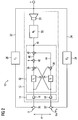
- FIG. 2 a hearing aid 12 with a microphone assembly 14 of two microphones 16, 18 is shown.
- the hearing aid 12 may be, for example, a behind-the-ear hearing aid, of which a in FIG. 2 not further illustrated housing with the microphone assembly 14 is located behind an ear of a device carrier.
- the hearing device 12 may also include, for example, a sound tube and an earmold.
- the earmold can be used in an ear canal of the equipment wearer.
- a receiver 20 of the hearing aid 12 By a receiver 20 of the hearing aid 12, a sound is generated, which is passed through the sound tube and earmold in the ear canal.
- another type of earmold can also be provided.
- An air surrounding the hearing device 12 and the ear of the equipment wearer form an environment of the hearing device 12, which together with the hearing aid 12 form a system 10, in which it can come to a feedback.
- the feedback paths 22, 24 are formed, via which a sound Y of the listener 20 can get to the microphone assembly 14.
- the feedback paths 22, 24 include, for example, an acoustic propagation path which passes through a vent opening of the earmold.
- the sound signal Y is changed according to a transfer function F 1 , which in FIG. 2 designated by the reference numeral 26.
- F 2 For the feedback path 24 results in a transfer function F 2 , which in FIG. 2 designated by the reference numeral 28.
- a sound X is received by a sound source, which is located in a vicinity of the equipment carrier.
- the sound X also hits the microphone 18 with a time delay ⁇ e.
- the time delay ⁇ e depends on a distance d of the microphones 16, 18 and on an angle ⁇ between the direction of propagation of the sound X and an axis of the microphone arrangement 14 in the one described Way off.
- the sound X and the sound Y passed through the feedback paths 22, 24 are superimposed on the microphones 16, 18. This is in FIG. 2 indicated by sum symbols 30, 30 '.
- the hearing device 12 has a device 32 for generating a directivity of the microphone arrangement 14.
- the microphones 16 and 18 themselves can each have an omnidirectional directivity, ie each of the microphones 16, 18 detects a sound in this case, without direction.
- the device 32 comprises delay elements 34, by means of which a microphone signal can be delayed by a delay time ⁇ i . Such a delay may be effected, for example, by varying a phase of a spectral component of the microphone signal.
- the device 32 also includes summers 36, 38, 40, by means of which two signals can be superimposed, ie added, in each case. It is in the summers 36, 38 inverts one of the input signals before the superposition. This is in FIG. 2 indicated by a minus sign.
- the unit 32 further comprises a multiplier 42, by which a signal with a weighting factor a can be weighted, ie multiplied.
- a cardioid branch 44 and an anti-cardioid branch 46 are provided as signal paths.
- signal components are attenuated in accordance with a cardioid directional characteristic of the microphone arrangement 14.
- a signal is sent to the summer 40 via the anti-cardioid branch 46, in which signal portions are damped in accordance with an anti-cardioid directional characteristic of the microphone arrangement 14.
- a portion of the signal of the branch 46 on a sum signal at the output 48 of the unit 32 is determined by the weighting factor a.
- the weighting factor a is a directional parameter of the device 32.
- the output 48 of the unit 32 is coupled to an amplifier 50 of the hearing aid 12. Through the amplifier 50, a signal may be amplified in response to a hearing curve of the equipment wearer to compensate for hearing loss.
- a signal path consisting of the feedback path 22 and the electrical path from the microphone 16 to the listener 20 forms a first feedback loop.
- the feedback path 24 and the electrical signal path from the microphone 18 to the handset 20 together form a second feedback loop.
- the two feedback loops give a feedback effect. Of a gain along the feedback loops depends on whether a signal to a feedback in the sense already described, i. an audible whistle, leads.
- a stability limit of the system 10 can be calculated in dependence on values for the transfer functions F 1 and F 2 . Is a stability condition for the system 10 that the amount of the term H c [F i (1 + a exp (- j ⁇ i) -F 2 (a + exp (- j ⁇ i))] is less than or equal to 1. Then, the sound X does not generate feedback, that is, a sound Y of the listener 20 passing through the feedback paths 22 and 24 to the microphone assembly 14 generates a feedback effect so that a microphone signal in the hearing aid 12 can again be caused by it However, the signal is always attenuated along the feedback loop to such an extent that it automatically decays over time.
- summands C 1 and C 2 are less than 1, the system 10 is more stable than a system with a single omnidirectional microphone. Then, a larger amplification of the signal by the amplifier 50 is possible than in a Hearing aid with a single microphone.
- Both summands C 1 and C 2 depend on the weighting factor a for the anti-cardioid branch 46 and on the frequency ⁇ . Depending on the weighting factor a, the critical gain value is greater than in a hearing aid with a single omnidirectional microphone. In such a case, a correspondingly greater amplification can be provided by the hearing device 12 without a feedback being triggered in the process.
- a calculation of a maximum weighting factor a for the anti-cardioid branch 46 is possible, up to which a substantially feedback-free operation of the hearing aid 12 is possible.
- This calculation requires a measurement of the transfer functions F 1 and F 2 of the feedback paths 22, 24.
- Transfer functions F 1 and F 2 and further transfer functions for the individual feedback paths can be determined, for example, by a device carrier carrying a hearing device intended for it in the intended manner and test measurements, for example by a hearing care professional. On the basis of the transfer functions of the feedback paths thus determined, it is then possible to determine, for example, an interval a ⁇ a 0 of values for which a reduced-feedback operation results.
- the weighting factor a can then be limited to the maximum value a 0 , ie to the upper limit of the determined interval.
- a device carrier perceives such a limitation as reduced directivity in those situations in which feedback is expected.
- an algorithm for feedback suppression can also be controlled. If the weighting factor a is set to a value close to the maximum permissible value a 0 at a certain point in time, a relatively small change in the weighting factor a lead to an unstable system. Similarly, the instability may be caused by a slight change in the transfer functions F 1 or F 2 . If the system 10 is close to such a stability limit, then an adaptation rate of the feedback suppression algorithm can be increased. If it actually comes to a feedback, this is suppressed by the algorithm very quickly.
- a feedback suppression algorithm detection or detection may also be provided for feedback.
- an adaptive limitation of the weighting factor a can be made possible. If a feedback is detected, then a limit for the weighting factor a can be reduced. As a result, the instantaneous value of the weighting factor a itself is also reduced until the system is stable again. Then the feedback sounds self-contained. If no further feedback is subsequently detected for a predetermined period of time, the limit for the weighting factor a can be raised again. In such an adaptive limitation, it can be ensured by specifying appropriate time constants that no cyclic repetition of feedbacks is caused.
- the adaptive adaptation of the weighting factor a for the anti-cardioid branch 46 using the algorithm for feedback suppression results in the advantage that a hearing aid always allows a correspondingly maximum possible value for the weighting factor a even when the environment changes.
- a particular aspect of the invention is the ability to mathematically determine a stability limit for a system based on the directivity parameter a and the transfer functions F 1 , F 2 for feedback paths. This makes it possible to limit the weighting factor a, so that a stable system is always ensured. In this case, the predetermined for example by a hearing curve of a device carrier gain of the microphone signals are taken into account.
- a particularly high gain as is possible for hearing aids with only a single omnidirectional microphone, can also be achieved for a hearing aid with directivity.
- a notch of a directional characteristic is such a detection direction, for which results in a comparatively strong attenuation.
- a control device 52 a directional microphone device 54 and a device for suppressing a feedback, ie a feedback suppression 56, are shown.
- the three devices 52, 54, 56 may be provided as programs on a signal processing processor of a hearing device.
- the directional microphone device 54 can process signals of a microphone arrangement, for example in the manner explained in connection with the device 32, in order to generate a directional characteristic for the microphone arrangement.
- the feedback suppression 56 may be configured to estimate transfer functions of feedback paths to generate a compensation signal from the estimated transfer functions to attenuate a signal of acoustic feedback.
- the directional microphone device 54 and the feedback suppression 56 are each coupled to the controller 52.
- a directional parameter of the directional microphone device 54 is adjustable.
- a step size for an adaptation algorithm of the feedback suppression 56 can be set by the control device 52.
- instantaneous values of these parameters can also be read from the directional microphone device 54 and the feedback suppression 56.
- the estimated transfer functions for the feedback paths from the feedback suppression 56 can also be read out.
- the control device 52 is designed to use these values to determine the directional parameter or the step size in connection with FIG. 2 to control described manner.
- the hearing device it is possible in the hearing device to control the directional microphone device 54 and / or the feedback suppression 56 to prevent or suppress an acoustic feedback accordingly.
Landscapes
- Health & Medical Sciences (AREA)
- General Health & Medical Sciences (AREA)
- Neurosurgery (AREA)
- Otolaryngology (AREA)
- Physics & Mathematics (AREA)
- Engineering & Computer Science (AREA)
- Acoustics & Sound (AREA)
- Signal Processing (AREA)
- Circuit For Audible Band Transducer (AREA)
Claims (8)
- Procédé pour faire fonctionner une prothèse ( 12 ) auditive, dans laquelle un paramètre directionnel est réglable pour la fixation d'une caractéristique directionnelle d'un agencement ( 14 ) de microphone de la prothèse ( 12 ) auditive,
comprenant les stades dans lesquels :- on prescrit une condition de stabilité pour un fonctionnement à réaction diminuée de la prothèse ( 12 ) auditive en fonction du paramètre directionnel ;- on détermine les valeurs du paramètre directionnel pour lesquelles la condition de stabilité est satisfaite ;- on limite les valeurs possibles du paramètre directionnel en fonctionnement de la prothèse auditive aux valeurs déterminées. - Procédé suivant la revendication 1,
dans lequel on prescrit un terme d'un dénominateur d'une fonction globale de transfert et à cet effet le terme comprend au moins le paramètre ( a ) directionnel et une fonction ( 26, 28 ) de transfert d'un trajet ( 22, 24 ) de réaction,
et dans lequel on détermine les valeurs du paramètre ( a ) directionnel pour lesquelles il est satisfait, comme condition de stabilité, que le terme satisfait un critère déterminé à l'avance. - Procédé suivant la revendication 1 ou 2,
dans lequel on détermine les valeurs en fonction d'une fréquence d'un signal. - Procédé suivant l'une des revendications 2 ou 3, dans lequel on forme la fonction globale de transfert sous la forme d'un quotient A/B
dans lequel A=[1-exp(-j ω(τe+τi))]Hc et
B=1-Hc[F1(1+a exp (-j ωτi ) ) -F2 (a+exp (-j ω τi ))] et ainsi- une fonction F1 de transfert d'un premier trajet de réaction et une fonction F2 de transfert d'un deuxième trajet de réaction,- une fonction Hc d'amplification de la prothèse auditive,- une fréquence ω d'un signal,- un temps τi de temporisation et un facteur a de pondération comme les paramètres directionnels par lesquels la caractéristique directionnelle de l'agencement de microphone est fixée, et- un temps τe de parcours d'un son entre deux microphones de l'agencement de microphone. - Procédé suivant l'une des revendications précédentes, dans lequel, pour la détermination des valeurs du facteur a de pondération, on contrôle si une valeur absolue du terme Hc[F1( 1+a exp (-j ω τi)) -F2 ( a+exp (-j ω τi )) ] est plus petite qu'une valeur limite de stabilité, notamment plus petite que un.
- Procédé pour faire fonctionner une prothèse ( 12 ) auditive dans laquelle on peut régler, comme premier paramètre, un paramètre directionnel pour la fixation d'une caractéristique directionnelle d'un agencement ( 14 ) de microphone et, comme deuxième paramètre, un paramètre de commande pour la commande d'un dispositif ( 56 ) de suppression de la réaction, comprenant les stades dans lesquels :- on prescrit une mesure pour un effet de réaction ;- on détermine une valeur de la mesure au moyen d'une valeur instantanée du paramètre directionnel ;- on règle au moins l'un des paramètres en fonction de la valeur déterminée,caractérisé en ce quea) on prescrit comme mesure de l'effet de réaction une mesure d'écart à une limite de stabilité en fonction du paramètre directionnel, et
on règle comme paramètre un pas de progression d'un algorithme d'adaptation de l'unité de suppression de la réaction et on augmente ainsi une vitesse d'adaptation de l'algorithme d'adaptation si la prothèse auditive fonctionne près de la limite de stabilité et/oub) on analyse comme mesure de l'effet de réaction s'il y a une réaction, et
au stade du réglage, on modifie la valeur instantanée du paramètre directionnel jusqu'à ce qu'un effet de réaction devienne inférieur à un seuil prescrit. - Prothèse ( 12 ) auditive comprenant
un agencement de microphone et un dispositif ( 56 ) de suppression d'une réaction, dans laquelle
sont réglables, comme premier paramètre, un paramètre directionnel pour la fixation d'une caractéristique directionnelle d'un agencement ( 14 ) de microphone et, comme deuxième paramètre, un paramètre de commande pour la commande du dispositif ( 56 ) de suppression d'une réaction, caractérisée par
un dispositif ( 52 ) de commande, qui est conçu pour faire fonctionner la prothèse auditive suivant un procédé suivant l'une des revendications précédentes. - Prothèse auditive suivant la revendication 7, dans laquelle la caractéristique directionnelle de l'agencement ( 14 ) de microphone peut être produite par une superposition d'une caractéristique ( 44 ) directionnelle en cardioïde et d'une caractéristique ( 46 ) directionnelle anti-cardioïde et une partie de la caractéristique directionnelle anti-cardioïde est déterminée par le paramètre directionnel.
Applications Claiming Priority (1)
| Application Number | Priority Date | Filing Date | Title |
|---|---|---|---|
| DE102010011729A DE102010011729A1 (de) | 2010-03-17 | 2010-03-17 | Hörvorrichtung und Verfahren zum Einstellen derselben für einen rückkopplungsfreien Betrieb |
Publications (2)
| Publication Number | Publication Date |
|---|---|
| EP2373063A1 EP2373063A1 (fr) | 2011-10-05 |
| EP2373063B1 true EP2373063B1 (fr) | 2012-06-20 |
Family
ID=43902551
Family Applications (1)
| Application Number | Title | Priority Date | Filing Date |
|---|---|---|---|
| EP11154523A Active EP2373063B1 (fr) | 2010-03-17 | 2011-02-15 | Dispositif auditif et procédé de réglage de celui-ci pour un fonctionnement sans contre-réaction |
Country Status (4)
| Country | Link |
|---|---|
| US (1) | US8452035B2 (fr) |
| EP (1) | EP2373063B1 (fr) |
| DE (1) | DE102010011729A1 (fr) |
| DK (1) | DK2373063T3 (fr) |
Families Citing this family (5)
| Publication number | Priority date | Publication date | Assignee | Title |
|---|---|---|---|---|
| DE102012008557B4 (de) | 2012-03-16 | 2018-09-13 | Iav Gmbh Ingenieurgesellschaft Auto Und Verkehr | Verfahren zur Rückkopplungsunterdrückung in elektroakustischen Systemen |
| US20140270291A1 (en) * | 2013-03-15 | 2014-09-18 | Mark C. Flynn | Fitting a Bilateral Hearing Prosthesis System |
| US9763006B2 (en) | 2015-03-26 | 2017-09-12 | International Business Machines Corporation | Noise reduction in a microphone using vowel detection |
| EP3139636B1 (fr) * | 2015-09-07 | 2019-10-16 | Oticon A/s | Dispositif auditif comprenant un système d'annulation de rétroaction sur la base d'une relocalisation de l'énergie d'un signal |
| DE102018208657B3 (de) | 2018-05-30 | 2019-09-26 | Sivantos Pte. Ltd. | Verfahren zur Verringerung eines Auftretens einer akustischen Rückkopplung in einem Hörgerät |
Family Cites Families (7)
| Publication number | Priority date | Publication date | Assignee | Title |
|---|---|---|---|---|
| DE19844748A1 (de) * | 1998-09-29 | 1999-10-07 | Siemens Audiologische Technik | Verfahren zum Bereitstellen einer Richtmikrofoncharakteristik und Hörgerät |
| DE10313330B4 (de) * | 2003-03-25 | 2005-04-14 | Siemens Audiologische Technik Gmbh | Verfahren zur Unterdrückung mindestens eines akustischen Störsignals und Vorrichtung zur Durchführung des Verfahrens |
| CN1934903B (zh) * | 2004-03-23 | 2015-02-18 | 奥迪康有限公司 | 具有抗反馈系统的助听器 |
| DE102005019149B3 (de) * | 2005-04-25 | 2006-08-31 | Siemens Audiologische Technik Gmbh | Hörhilfevorrichtung mit Kompensation von akustischen und elektromagnetischen Rückkopplungssignalen |
| WO2007042025A1 (fr) * | 2005-10-11 | 2007-04-19 | Widex A/S | Prothèse auditive et procédé de traitement de signaux d'entrée dans une prothèse auditive |
| DK2317778T3 (da) * | 2006-03-03 | 2019-06-11 | Widex As | Høreapparat og fremgangsmåde til at anvende forstærkningsbegrænsning i et høreapparat |
| JP4923102B2 (ja) * | 2006-04-01 | 2012-04-25 | ヴェーデクス・アクティーセルスカプ | 補聴器,および補聴器のためのアンチ・フィードバック・システムにおける適応速度の制御方法 |
-
2010
- 2010-03-17 DE DE102010011729A patent/DE102010011729A1/de not_active Ceased
-
2011
- 2011-02-15 DK DK11154523.2T patent/DK2373063T3/da active
- 2011-02-15 EP EP11154523A patent/EP2373063B1/fr active Active
- 2011-03-17 US US13/050,093 patent/US8452035B2/en active Active
Also Published As
| Publication number | Publication date |
|---|---|
| DK2373063T3 (da) | 2012-10-01 |
| US20110228960A1 (en) | 2011-09-22 |
| EP2373063A1 (fr) | 2011-10-05 |
| US8452035B2 (en) | 2013-05-28 |
| DE102010011729A1 (de) | 2011-09-22 |
Similar Documents
| Publication | Publication Date | Title |
|---|---|---|
| EP3451705B1 (fr) | Procédé et dispositif de reconnaissance rapide de voix propre | |
| EP1489885B1 (fr) | Procédé pour l'opération d'une prothèse auditive ainsi qu'une prothèse auditive avec un système de microphone dans lequel différents caractéristiques de directivité sont sélectionnables | |
| DE102007017761B4 (de) | Verfahren zur Anpassung eines binauralen Hörgerätesystems | |
| EP2451194A2 (fr) | Procédé et appareil auditif destinés à la détermination de l'humidité | |
| EP2229010B1 (fr) | Appareil auditif et procédé de compensation du bruit dans un appareil auditif | |
| EP2114089A1 (fr) | Procédé et dispositif de détermination d'un degré de fermeture dans des appareils auditifs | |
| DE102006047965A1 (de) | Hörhilfsgerät mit einer Okklusionsreduktionseinrichtung und Verfahren zur Okklusionsreduktion | |
| EP2226795B1 (fr) | Dispositif auditif et procédé de réduction d'un bruit parasite pour un dispositif auditif | |
| EP2988529B1 (fr) | Frequence de division adaptative dans appareils d'aide auditive | |
| EP2595414B1 (fr) | Dispositif auditif avec un système pour réduire un bruit de microphone et procédé de réduction d'un bruit de microphone | |
| EP2373063B1 (fr) | Dispositif auditif et procédé de réglage de celui-ci pour un fonctionnement sans contre-réaction | |
| DE102011006129B4 (de) | Hörvorrichtung mit Rückkopplungsunterdrückungseinrichtung und Verfahren zum Betreiben der Hörvorrichtung | |
| EP2811762B1 (fr) | Système binaural de formation de faisceau fondé sur la logique | |
| DE102020207579A1 (de) | Verfahren zur richtungsabhängigen Rauschunterdrückung für ein Hörsystem, welches eine Hörvorrichtung umfasst | |
| EP2981099B1 (fr) | Procede et dispositif de suppression de l'effet larsen | |
| DE102008046040B4 (de) | Verfahren zum Betrieb einer Hörvorrichtung mit Richtwirkung und zugehörige Hörvorrichtung | |
| DE102014218672B3 (de) | Verfahren und Vorrichtung zur Rückkopplungsunterdrückung | |
| DE102010007336A1 (de) | Verfahren zum Kompensieren eines Rückkopplungssignals und Hörvorrichtung | |
| EP2658289B1 (fr) | Procédé de commande d'une caractéristique de guidage et système auditif | |
| DE102008036803B3 (de) | Anordnung und Verfahren zur Regelung einer Rückkopplungsunterdrückung bei Hörvorrichtungen | |
| EP2373065B2 (fr) | Dispositif auditif et procédé de production d'une caractéristique de direction omnidirectionnelle | |
| EP2648424B1 (fr) | Procédé de limitation du niveau de sortie pour des appareils auditifs | |
| DE102011087692B4 (de) | Hörvorrichtung und Verfahren zur Verbesserung der Wahrnehmbarkeit eines Anteils eines Eingangssignals für einen Benutzer der Hörvorrichtung | |
| EP2699020B1 (fr) | Procédé et dispositif de détermination d'un facteur d'amplification d'un appareil de correction auditive | |
| WO2011107545A2 (fr) | Procédé pour régler un dispositif d'audition à effet directif |
Legal Events
| Date | Code | Title | Description |
|---|---|---|---|
| PUAI | Public reference made under article 153(3) epc to a published international application that has entered the european phase |
Free format text: ORIGINAL CODE: 0009012 |
|
| AK | Designated contracting states |
Kind code of ref document: A1 Designated state(s): AL AT BE BG CH CY CZ DE DK EE ES FI FR GB GR HR HU IE IS IT LI LT LU LV MC MK MT NL NO PL PT RO RS SE SI SK SM TR |
|
| AX | Request for extension of the european patent |
Extension state: BA ME |
|
| 17P | Request for examination filed |
Effective date: 20110919 |
|
| GRAP | Despatch of communication of intention to grant a patent |
Free format text: ORIGINAL CODE: EPIDOSNIGR1 |
|
| GRAS | Grant fee paid |
Free format text: ORIGINAL CODE: EPIDOSNIGR3 |
|
| GRAA | (expected) grant |
Free format text: ORIGINAL CODE: 0009210 |
|
| AK | Designated contracting states |
Kind code of ref document: B1 Designated state(s): AL AT BE BG CH CY CZ DE DK EE ES FI FR GB GR HR HU IE IS IT LI LT LU LV MC MK MT NL NO PL PT RO RS SE SI SK SM TR |
|
| REG | Reference to a national code |
Ref country code: GB Ref legal event code: FG4D Free format text: NOT ENGLISH |
|
| REG | Reference to a national code |
Ref country code: CH Ref legal event code: EP Ref country code: CH Ref legal event code: NV Representative=s name: SIEMENS SCHWEIZ AG |
|
| REG | Reference to a national code |
Ref country code: AT Ref legal event code: REF Ref document number: 563602 Country of ref document: AT Kind code of ref document: T Effective date: 20120715 |
|
| REG | Reference to a national code |
Ref country code: IE Ref legal event code: FG4D Free format text: LANGUAGE OF EP DOCUMENT: GERMAN |
|
| REG | Reference to a national code |
Ref country code: DE Ref legal event code: R096 Ref document number: 502011000042 Country of ref document: DE Effective date: 20120816 |
|
| REG | Reference to a national code |
Ref country code: DK Ref legal event code: T3 |
|
| PG25 | Lapsed in a contracting state [announced via postgrant information from national office to epo] |
Ref country code: SE Free format text: LAPSE BECAUSE OF FAILURE TO SUBMIT A TRANSLATION OF THE DESCRIPTION OR TO PAY THE FEE WITHIN THE PRESCRIBED TIME-LIMIT Effective date: 20120620 Ref country code: FI Free format text: LAPSE BECAUSE OF FAILURE TO SUBMIT A TRANSLATION OF THE DESCRIPTION OR TO PAY THE FEE WITHIN THE PRESCRIBED TIME-LIMIT Effective date: 20120620 Ref country code: LT Free format text: LAPSE BECAUSE OF FAILURE TO SUBMIT A TRANSLATION OF THE DESCRIPTION OR TO PAY THE FEE WITHIN THE PRESCRIBED TIME-LIMIT Effective date: 20120620 Ref country code: NO Free format text: LAPSE BECAUSE OF FAILURE TO SUBMIT A TRANSLATION OF THE DESCRIPTION OR TO PAY THE FEE WITHIN THE PRESCRIBED TIME-LIMIT Effective date: 20120920 Ref country code: RS Free format text: LAPSE BECAUSE OF FAILURE TO SUBMIT A TRANSLATION OF THE DESCRIPTION OR TO PAY THE FEE WITHIN THE PRESCRIBED TIME-LIMIT Effective date: 20120620 |
|
| REG | Reference to a national code |
Ref country code: NL Ref legal event code: VDEP Effective date: 20120620 |
|
| REG | Reference to a national code |
Ref country code: LT Ref legal event code: MG4D Effective date: 20120620 |
|
| PG25 | Lapsed in a contracting state [announced via postgrant information from national office to epo] |
Ref country code: GR Free format text: LAPSE BECAUSE OF FAILURE TO SUBMIT A TRANSLATION OF THE DESCRIPTION OR TO PAY THE FEE WITHIN THE PRESCRIBED TIME-LIMIT Effective date: 20120921 Ref country code: SI Free format text: LAPSE BECAUSE OF FAILURE TO SUBMIT A TRANSLATION OF THE DESCRIPTION OR TO PAY THE FEE WITHIN THE PRESCRIBED TIME-LIMIT Effective date: 20120620 Ref country code: LV Free format text: LAPSE BECAUSE OF FAILURE TO SUBMIT A TRANSLATION OF THE DESCRIPTION OR TO PAY THE FEE WITHIN THE PRESCRIBED TIME-LIMIT Effective date: 20120620 Ref country code: HR Free format text: LAPSE BECAUSE OF FAILURE TO SUBMIT A TRANSLATION OF THE DESCRIPTION OR TO PAY THE FEE WITHIN THE PRESCRIBED TIME-LIMIT Effective date: 20120620 |
|
| PG25 | Lapsed in a contracting state [announced via postgrant information from national office to epo] |
Ref country code: IS Free format text: LAPSE BECAUSE OF FAILURE TO SUBMIT A TRANSLATION OF THE DESCRIPTION OR TO PAY THE FEE WITHIN THE PRESCRIBED TIME-LIMIT Effective date: 20121020 Ref country code: EE Free format text: LAPSE BECAUSE OF FAILURE TO SUBMIT A TRANSLATION OF THE DESCRIPTION OR TO PAY THE FEE WITHIN THE PRESCRIBED TIME-LIMIT Effective date: 20120620 Ref country code: SK Free format text: LAPSE BECAUSE OF FAILURE TO SUBMIT A TRANSLATION OF THE DESCRIPTION OR TO PAY THE FEE WITHIN THE PRESCRIBED TIME-LIMIT Effective date: 20120620 Ref country code: CZ Free format text: LAPSE BECAUSE OF FAILURE TO SUBMIT A TRANSLATION OF THE DESCRIPTION OR TO PAY THE FEE WITHIN THE PRESCRIBED TIME-LIMIT Effective date: 20120620 Ref country code: RO Free format text: LAPSE BECAUSE OF FAILURE TO SUBMIT A TRANSLATION OF THE DESCRIPTION OR TO PAY THE FEE WITHIN THE PRESCRIBED TIME-LIMIT Effective date: 20120620 Ref country code: CY Free format text: LAPSE BECAUSE OF FAILURE TO SUBMIT A TRANSLATION OF THE DESCRIPTION OR TO PAY THE FEE WITHIN THE PRESCRIBED TIME-LIMIT Effective date: 20120620 |
|
| PG25 | Lapsed in a contracting state [announced via postgrant information from national office to epo] |
Ref country code: PL Free format text: LAPSE BECAUSE OF FAILURE TO SUBMIT A TRANSLATION OF THE DESCRIPTION OR TO PAY THE FEE WITHIN THE PRESCRIBED TIME-LIMIT Effective date: 20120620 Ref country code: IT Free format text: LAPSE BECAUSE OF FAILURE TO SUBMIT A TRANSLATION OF THE DESCRIPTION OR TO PAY THE FEE WITHIN THE PRESCRIBED TIME-LIMIT Effective date: 20120620 Ref country code: PT Free format text: LAPSE BECAUSE OF FAILURE TO SUBMIT A TRANSLATION OF THE DESCRIPTION OR TO PAY THE FEE WITHIN THE PRESCRIBED TIME-LIMIT Effective date: 20121022 |
|
| PG25 | Lapsed in a contracting state [announced via postgrant information from national office to epo] |
Ref country code: NL Free format text: LAPSE BECAUSE OF FAILURE TO SUBMIT A TRANSLATION OF THE DESCRIPTION OR TO PAY THE FEE WITHIN THE PRESCRIBED TIME-LIMIT Effective date: 20120620 |
|
| PLBE | No opposition filed within time limit |
Free format text: ORIGINAL CODE: 0009261 |
|
| STAA | Information on the status of an ep patent application or granted ep patent |
Free format text: STATUS: NO OPPOSITION FILED WITHIN TIME LIMIT |
|
| 26N | No opposition filed |
Effective date: 20130321 |
|
| REG | Reference to a national code |
Ref country code: DE Ref legal event code: R097 Ref document number: 502011000042 Country of ref document: DE Effective date: 20130321 |
|
| PG25 | Lapsed in a contracting state [announced via postgrant information from national office to epo] |
Ref country code: BG Free format text: LAPSE BECAUSE OF FAILURE TO SUBMIT A TRANSLATION OF THE DESCRIPTION OR TO PAY THE FEE WITHIN THE PRESCRIBED TIME-LIMIT Effective date: 20120920 |
|
| BERE | Be: lapsed |
Owner name: SIEMENS MEDICAL INSTRUMENTS PTE. LTD. Effective date: 20130228 |
|
| PG25 | Lapsed in a contracting state [announced via postgrant information from national office to epo] |
Ref country code: MC Free format text: LAPSE BECAUSE OF NON-PAYMENT OF DUE FEES Effective date: 20130228 |
|
| PG25 | Lapsed in a contracting state [announced via postgrant information from national office to epo] |
Ref country code: ES Free format text: LAPSE BECAUSE OF FAILURE TO SUBMIT A TRANSLATION OF THE DESCRIPTION OR TO PAY THE FEE WITHIN THE PRESCRIBED TIME-LIMIT Effective date: 20121001 |
|
| REG | Reference to a national code |
Ref country code: IE Ref legal event code: MM4A |
|
| PG25 | Lapsed in a contracting state [announced via postgrant information from national office to epo] |
Ref country code: BE Free format text: LAPSE BECAUSE OF NON-PAYMENT OF DUE FEES Effective date: 20130228 Ref country code: IE Free format text: LAPSE BECAUSE OF NON-PAYMENT OF DUE FEES Effective date: 20130215 Ref country code: AL Free format text: LAPSE BECAUSE OF FAILURE TO SUBMIT A TRANSLATION OF THE DESCRIPTION OR TO PAY THE FEE WITHIN THE PRESCRIBED TIME-LIMIT Effective date: 20120620 |
|
| PG25 | Lapsed in a contracting state [announced via postgrant information from national office to epo] |
Ref country code: MT Free format text: LAPSE BECAUSE OF FAILURE TO SUBMIT A TRANSLATION OF THE DESCRIPTION OR TO PAY THE FEE WITHIN THE PRESCRIBED TIME-LIMIT Effective date: 20120620 |
|
| REG | Reference to a national code |
Ref country code: DE Ref legal event code: R082 Ref document number: 502011000042 Country of ref document: DE Representative=s name: FDST PATENTANWAELTE FREIER DOERR STAMMLER TSCH, DE |
|
| PG25 | Lapsed in a contracting state [announced via postgrant information from national office to epo] |
Ref country code: SM Free format text: LAPSE BECAUSE OF FAILURE TO SUBMIT A TRANSLATION OF THE DESCRIPTION OR TO PAY THE FEE WITHIN THE PRESCRIBED TIME-LIMIT Effective date: 20120620 |
|
| PG25 | Lapsed in a contracting state [announced via postgrant information from national office to epo] |
Ref country code: TR Free format text: LAPSE BECAUSE OF FAILURE TO SUBMIT A TRANSLATION OF THE DESCRIPTION OR TO PAY THE FEE WITHIN THE PRESCRIBED TIME-LIMIT Effective date: 20120620 |
|
| PG25 | Lapsed in a contracting state [announced via postgrant information from national office to epo] |
Ref country code: HU Free format text: LAPSE BECAUSE OF FAILURE TO SUBMIT A TRANSLATION OF THE DESCRIPTION OR TO PAY THE FEE WITHIN THE PRESCRIBED TIME-LIMIT; INVALID AB INITIO Effective date: 20110215 Ref country code: MK Free format text: LAPSE BECAUSE OF FAILURE TO SUBMIT A TRANSLATION OF THE DESCRIPTION OR TO PAY THE FEE WITHIN THE PRESCRIBED TIME-LIMIT Effective date: 20120620 Ref country code: LU Free format text: LAPSE BECAUSE OF NON-PAYMENT OF DUE FEES Effective date: 20130215 |
|
| REG | Reference to a national code |
Ref country code: DE Ref legal event code: R082 Ref document number: 502011000042 Country of ref document: DE Representative=s name: FDST PATENTANWAELTE FREIER DOERR STAMMLER TSCH, DE Ref country code: DE Ref legal event code: R081 Ref document number: 502011000042 Country of ref document: DE Owner name: SIVANTOS PTE. LTD., SG Free format text: FORMER OWNER: SIEMENS MEDICAL INSTRUMENTS PTE. LTD., SINGAPORE, SG |
|
| REG | Reference to a national code |
Ref country code: FR Ref legal event code: PLFP Year of fee payment: 6 |
|
| REG | Reference to a national code |
Ref country code: FR Ref legal event code: PLFP Year of fee payment: 7 |
|
| REG | Reference to a national code |
Ref country code: AT Ref legal event code: MM01 Ref document number: 563602 Country of ref document: AT Kind code of ref document: T Effective date: 20160215 |
|
| PG25 | Lapsed in a contracting state [announced via postgrant information from national office to epo] |
Ref country code: AT Free format text: LAPSE BECAUSE OF NON-PAYMENT OF DUE FEES Effective date: 20160215 |
|
| REG | Reference to a national code |
Ref country code: FR Ref legal event code: PLFP Year of fee payment: 8 |
|
| PGFP | Annual fee paid to national office [announced via postgrant information from national office to epo] |
Ref country code: CH Payment date: 20250301 Year of fee payment: 15 |
|
| PGFP | Annual fee paid to national office [announced via postgrant information from national office to epo] |
Ref country code: FR Payment date: 20250121 Year of fee payment: 15 |
|
| PGFP | Annual fee paid to national office [announced via postgrant information from national office to epo] |
Ref country code: GB Payment date: 20250124 Year of fee payment: 15 |
|
| REG | Reference to a national code |
Ref country code: CH Ref legal event code: U11 Free format text: ST27 STATUS EVENT CODE: U-0-0-U10-U11 (AS PROVIDED BY THE NATIONAL OFFICE) Effective date: 20260301 |
|
| PGFP | Annual fee paid to national office [announced via postgrant information from national office to epo] |
Ref country code: DE Payment date: 20260121 Year of fee payment: 16 Ref country code: DK Payment date: 20260121 Year of fee payment: 16 |