EP2373204B1 - Staubsauger - Google Patents
Staubsauger Download PDFInfo
- Publication number
- EP2373204B1 EP2373204B1 EP09744632.2A EP09744632A EP2373204B1 EP 2373204 B1 EP2373204 B1 EP 2373204B1 EP 09744632 A EP09744632 A EP 09744632A EP 2373204 B1 EP2373204 B1 EP 2373204B1
- Authority
- EP
- European Patent Office
- Prior art keywords
- motor
- suction fan
- fan unit
- vacuum cleaner
- motor housing
- Prior art date
- Legal status (The legal status is an assumption and is not a legal conclusion. Google has not performed a legal analysis and makes no representation as to the accuracy of the status listed.)
- Active
Links
Images


Classifications
-
- A—HUMAN NECESSITIES
- A47—FURNITURE; DOMESTIC ARTICLES OR APPLIANCES; COFFEE MILLS; SPICE MILLS; SUCTION CLEANERS IN GENERAL
- A47L—DOMESTIC WASHING OR CLEANING; SUCTION CLEANERS IN GENERAL
- A47L9/00—Details or accessories of suction cleaners, e.g. mechanical means for controlling the suction or for effecting pulsating action; Storing devices specially adapted to suction cleaners or parts thereof; Carrying-vehicles specially adapted for suction cleaners
-
- A—HUMAN NECESSITIES
- A47—FURNITURE; DOMESTIC ARTICLES OR APPLIANCES; COFFEE MILLS; SPICE MILLS; SUCTION CLEANERS IN GENERAL
- A47L—DOMESTIC WASHING OR CLEANING; SUCTION CLEANERS IN GENERAL
- A47L7/00—Suction cleaners adapted for additional purposes; Tables with suction openings for cleaning purposes; Containers for cleaning articles by suction; Suction cleaners adapted to cleaning of brushes; Suction cleaners adapted to taking-up liquids
- A47L7/0004—Suction cleaners adapted to take up liquids, e.g. wet or dry vacuum cleaners
- A47L7/0042—Gaskets; Sealing means
-
- A—HUMAN NECESSITIES
- A47—FURNITURE; DOMESTIC ARTICLES OR APPLIANCES; COFFEE MILLS; SPICE MILLS; SUCTION CLEANERS IN GENERAL
- A47L—DOMESTIC WASHING OR CLEANING; SUCTION CLEANERS IN GENERAL
- A47L9/00—Details or accessories of suction cleaners, e.g. mechanical means for controlling the suction or for effecting pulsating action; Storing devices specially adapted to suction cleaners or parts thereof; Carrying-vehicles specially adapted for suction cleaners
- A47L9/0081—Means for exhaust-air diffusion; Means for sound or vibration damping
-
- A—HUMAN NECESSITIES
- A47—FURNITURE; DOMESTIC ARTICLES OR APPLIANCES; COFFEE MILLS; SPICE MILLS; SUCTION CLEANERS IN GENERAL
- A47L—DOMESTIC WASHING OR CLEANING; SUCTION CLEANERS IN GENERAL
- A47L9/00—Details or accessories of suction cleaners, e.g. mechanical means for controlling the suction or for effecting pulsating action; Storing devices specially adapted to suction cleaners or parts thereof; Carrying-vehicles specially adapted for suction cleaners
- A47L9/22—Mountings for motor fan assemblies
Definitions
- the present intention relates to a vacuum cleaner comprising a motor housing provided with an inlet and an outlet.
- Said vacuum cleaner further comprising a motor and suction fan unit, which is arranged in the motor housing and which is arranged to create a suction flow in through the inlet of the housing, through the motor and suction fan unit and out through the outlet of the motor housing.
- Vacuum cleaners of today are most commonly equipped with a motor and suction fan unit arranged inside a vacuum cleaner casing.
- the motor and suction fan is normally enclosed in a casing, which is arranged in a motor housing.
- the motor housing is surrounded by an appealingly designed vacuum cleaner casing.
- a problem with the present vacuum cleaners is the disturbing noise during operation of the vacuum cleaner.
- noise sources in a vacuum cleaner such as the suction flow itself and the motor sound.
- some of the noise originates from vibrations transferred from the motor and suction fan unit to the motor housing and the vacuum cleaner casing of the vacuum cleaner.
- the ring is arranged to seal between a dust collection space and the inlet of a motor and suction fan unit, and to support the motor and suction fan unit while simultaneously protect the housing from the vibrations originating in the motor and suction fan unit.
- JP 5 084194 (Matsushita electric kind co ltd) 6 April 1993.
- the invention is based on the insight that the requests/demands on said polymeric ring of being able to seal and to limit propagation of vibrations are contradictory. If the ring is made less rigid to provide more efficient damping, this results in poorer sealing properties, and correspondingly, if the ring is made more rigid to provide more efficient sealing, this results in less efficient limitation of vibration propagation. Based on this insight, a solution to redesign the above mentioned sealing and supporting polymeric ring from being a component sealing the suction flow, holding the motor and suction fan unit and damping vibrations into holding means and sealing means, which are optimized in different functions.
- the holding means can be designed to hold the motor and suction fan unit and to damp vibrations independently of the design of the sealing means
- the sealing means can be designed to seal independently of the design of the holding means.
- the sealing means can be designed to seal while not transfer any forces or vibration to the motor housing. Therefore the sealing and holding can be more efficient in preventing propagation of vibrations than previous designs, and an efficient prevention of vibration propagation implies a lower sound level. The frequently occurring penetrating tone of the motor and suction fan unit, often perceived as annoying, can be reduced.
- a vacuum cleaner of the present invention provides a simple construction of a more silent vacuum cleaner.
- a vacuum cleaner comprising a motor housing provided with an inlet and an outlet, a motor and suction fan unit, which is arranged in the motor housing and which is arranged to create a suction flow in through the inlet of the housing, through the motor and suction fan unit and out through the outlet of the motor housing.
- the vacuum cleaner further comprise holding means for holding the motor and suction fan unit at the motor housing, and sealing means arranged to seal between the inlet of the motor housing and the motor and suction fan unit to guide the suction flow from the inlet of the motor housing and into the motor and suction fan unit.
- the holding means is arranged to prevent propagation of vibrations originated in the motor and suction fan unit to the motor housing by the holding means responding resiliently to forces from the motor and suction fan unit, wherein the holding means carries the motor and suction fan unit at the housing.
- the sealing means is arranged to prevent propagation of vibrations originated in the motor and suction fan unit to the motor housing by yielding to forces from the motor and suction fan unit.
- the expression “responding resiliently to forces” means an elastic or flexible response, whereby the shape and size of the holding means recover quickly when the force is removed.
- the expression “yielding to forces” means a giving way to forces, for example by a bending or a folding movement, whereby the recovering tendency of the sealing means when the force is removed is low or absent.
- the vacuum cleaner can be any type of vacuum cleaner comprising a motor and suction fan unit arranged inside a casing, for example a canister type of vacuum cleaner, a central vacuum cleaner or an upright type of vacuum cleaner.
- the motor and suction fan unit is normally arranged to create a suction flow of air.
- the vacuum cleaner can be provided with a traditional filter bag for dust collection or can be provided with a cyclone filter or a cyclone separator.
- the motor and suction fan unit can be enclosed in a motor and suction fan unit casing.
- a motor housing encloses the motor and suction fan unit, the motor and suction fan unit casing and the holding means.
- the motor housing is normally arranged inside a vacuum cleaner casing.
- the vacuum cleaner of the present invention comprises holding means arranged to hold the motor and suction fan unit at the motor housing.
- the holding means is arranged to withstand the suction forces during vacuum cleaning and the gravity force of the motor and suction fan unit.
- the holding means is further arranged to respond resiliently to forces from the motor and suction fan unit, such as vibrations forces or twisting forces. The vibrations can therefore, at least to some extent, be isolated inside the motor housing, prevented from further propagation.
- a vacuum cleaner wherein the sealing means and the holding means are separate units.
- the sealing means and the holding means can be arranged in connection to each other or separate from each other.
- the sealing means can for example be connected to the holding means by a band or a beam.
- An advantage of holding and sealing means arranged as separate units is that the holding means and the sealing means can be manufactured in different materials.
- the holding means can also be placed independently of the position of the sealing means.
- the holding and sealing means area single component having differently optimized portions, i.e. a sealing portion and a holding portion.
- the holding means can be designed to respond to vibrations with a dampening effect, for example by comprising a separate damper or by an internal damping factor in the material or construction of the holding means.
- the holding means can comprise a hydraulic damper or a rubber damper. This is advantageous in that the vibrations of the motor and suction fan unit not only will be prevented from propagating to the motor housing, but also will be reduced or even eliminated.
- the holding means can further comprise a resilient or damping cushion element, which is arranged between a motor and suction fan wall and a motor housing wall.
- the cushion element can be any suitable resilient and/or damping element, such as a pad, a porous pad or an air filled pad.
- the cushion element can be a ring-shaped component.
- the ring-shaped component can comprise load-carrying protrusions which can be evenly distributed.
- the holding means can for example be made of a polymer, a rubber, a thermoelastic polymer, a silicone, a polyurethane material or a polyurethane foam.
- the holding means of the present invention can comprise at least one spring arranged between a motor and suction fan wall and a motor housing wall.
- the dimension of the spring can be adjusted to respond to vibrations from the motor and suction fan unit by not being completely compressed nor completely stretched out.
- the spring can further be dimensioned considering the risk of resonances.
- the spring can be arranged to respond resiliently to forces from the motor and suction fan unit.
- Several springs can be arranged, connecting the motor and suction fan unit to the motor housing.
- the spring can for example be a helical spring, a rubber spring or a gas spring.
- the vacuum cleaner of the present invention further comprises sealing means, arranged to guide the suction flow into the motor and suction fan unit.
- the sealing means is arranged to be flexible and yield to forces in the flow direction while being rigid and resistant to compressive load in the radial direction. This construction prevents the transfer of vibrations from the motor and suction fan unit via the sealing means to the motor housing, while at the same time withstand the suction pressure on the inside and the compressive load on the outside of the sealing means.
- the sealing means can be arranged to avoid short-cut, feedback or an opposite directed flow.
- the sealing means can comprise a tubular hollow space arranged between a motor housing and the motor and suction fan unit to guide the suction flow.
- the tubular hollow space can be circular whereby the tendency to collapse by the suction force is reduced.
- the sealing means can for example be made of a polymer, a rubber, a thermoelastic polymer, a silicone, a polyurethane material or a polyurethane foam.
- the sealing means can comprise a bellows.
- the bellows is a flexible and extensible sealing arranged to yielding to forces from the motor and suction fan unit while being rigid and resistant to compressive load in the radial direction.
- the bellows is unable to carry the motor and suction fan unit at the housing wall, and is arranged such that vibrations of the motor and suction fan unit are prevented from being transmitted via the bellows to the motor housing.
- the motor and suction fan unit during operation, can be carried by the holding means only. This is preferably for the prevention of vibration propagation, as all the vibration transmission from the motor and suction fan unit then is forced to transmit via the holding means, which is arranged to respond resiliently to vibrations and can comprise damping means.
- the sealing means is centrally arranged while the holding means is arranged at the periphery.
- the motor and suction fan unit can comprise a casing having a first wall with a central inlet, wherein the sealing means is arranged at the central inlet and extends to the motor housing inlet.
- the holding means can be arranged at an outermost end of the first wall of the motor and suction fan unit casing and be connected to the motor housing wall. This is advantageous as it is effective to damp vibrations as far out in the periphery of the motor and suction fan unit casing as possible, where the construction of the casing is more stiff or rigid.
- the first wall of the motor and suction fan unit casing is a top wall during normal use of the vacuum cleaner, and the motor and suction fan unit is hanging in the holding means from the motor housing wall.
- the force of the suction flow can then lift the motor and suction fan unit from the bottom of the motor housing when the motor and suction fan unit is turned on.
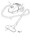
- Fig. 1 shows a perspective view of a vacuum cleaner 1 according to a preferred embodiment of the invention.
- the vacuum cleaner includes a nozzle 2, a tube 4 and a vacuum cleaner casing 6 wherein a dust collection space and a machinery unit with a motor and suction fan unit are embodied.
- Fig. 2 and 3 are sectional perspective views of a part of a vacuum cleaner 1 according to an embodiment of the invention.
- the vacuum cleaner 1 comprise a vacuum cleaner casing 6, a dust bag 10, a motor housing 12, a motor and suction fan unit 14 enclosed by a motor and suction fan unit casing 15, a sealing means in the form of a bellows 16, holding means 18 and a HEPA filter 20.
- Fig. 2 the vacuum cleaner 1 is in operation and the path of the suction flow 22 inside the vacuum cleaner 1 is shown with arrows.
- Fig. 3 the motor and suction fan unit 14 is turned off and is resting inside the motor housing 12.
- the motor housing 12 is provided with an inlet 28 and an outlet 30.
- a bellows 16 is mounted at the inlet 28, connecting the inlet 28 of the motor housing 12 to a centrally arranged inlet of the motor and suction fan unit casing 15.
- the bellows 16 is sealing the suction flow 22 on the inside of the bellows 16 from the overpressure on its outside.
- the motor and suction fan unit 14 is arranged inside a circular motor and suction fan unit casing 15, which is mounted to the motor housing 12 via the holding means 18.
- the holding means 18 are in the form of a cushion ring made of polyurethane, connecting the top wall 24 of the motor and suction fan unit casing 15 to the top wall 26 of the motor housing 12.
- the cushion ring is provided at the outermost periphery of the upper wall 24 of the motor and suction fan unit casing 15.
- the motor and suction fan unit casing 15 is only attached at its top wall 26, via the holding means 18 and the bellows 16, to the motor housing 12.
- the inner walls of the motor housing 12 are covered with a sound absorbing layer 32.
- a HEPA filter 20 is arranged at an outlet of the vacuum cleaner casing 6.
- the vacuum cleaner 1 according to the invention can be operated in the following way.
- the motor and suction fan unit 14 When the user turns on the vacuum cleaner 1, the motor and suction fan unit 14 is turned on whereby a suction flow 22 is created.
- the suction flow 22 withdraws for example dust from the area adjacent to the nozzle 2 of the vacuum cleaner 1.
- the suction flow 22 with the dust follows the tube 4 into the vacuum cleaner casing 6 where it enters the dust bag 10.
- the dust is collected in the dust bag 10, while the suction flow 22 passes through the walls of the dust bag 10.
- the suction flow 22 enters the motor and suction fan unit 14 via the inlet 28 of the motor housing 12 and the bellows 16. After passing the motor and suction fan unit 14, the suction flow 22 (actually turned into an exhaustion flow) is blown out of the vacuum cleaner casing 6 via the HEPA filter 20.
- the sound absorbing layer 32 along the path of the suction flow absorbs airborne noise.
- Fig. 4 the bellows 16 of a preferred embodiment of the present invention is shown in a close up, partly in cross section. Further, the holding means 18 are shown, here provided with four protruding cushions symmetrically arranged around the bellows 16. The holding means 18 are arranged on top of the motor and suction fan unit 14.
- Fig. 5 shows an alternative embodiment of the invention wherein the holding means 18 comprise four springs 40.
- the springs 40 are helical and are symmetrically arranged around the bellows 16.
- the springs 40 responds resiliently to the vibrations, without transferring any vibrations to the motor housing 12.
Landscapes
- Engineering & Computer Science (AREA)
- Mechanical Engineering (AREA)
- Electric Suction Cleaners (AREA)
Claims (12)
- Staubsauger (1) mit einer Umhüllung, der Folgendes aufweist,- ein Motorgehäuse (12) innerhalb der Umhüllung und mit einem Einlass (28) und einem Auslass (30),- eine Motor- und Sauggebläseeinheit (14), die von einer für die Motor- und Sauggebläseeinheit vorgesehenen Umhüllung (15) umschlossen ist, die im Motorgehäuse (12) angeordnet und so vorgesehen ist, dass eine Saugströmung (22) entsteht, die hinein durch den Einlass (28) des Motorgehäuses (12), durch die Motor- und Sauggebläseeinheit (14) und heraus durch den Auslass (30) des Motorgehäuses (12) erfolgt,- Haltemittel (18), um die für die Motor- und Sauggebläseeinheit vorgesehene Umhüllung (15) am Motorgehäuse (12) zu halten,- Abdichtungsmittel (16), um die Saugströmung (22) vom Einlass (28) des Motorgehäuses (12) und hinein in die Motor- und Sauggebläseeinheit (14) in einer dichten Weise zu führen, wobei- das Haltemittel (18) angeordnet ist, um zu verhindern, dass sich aus der Motor- und Sauggebläseeinheit (14) stammende Vibrationen auf das Motorgehäuse (12) übertragen, wobei das Haltemittel (18) in elastischer Weise auf von der Motor- und Sauggebläseeinheit (14) stammende Kräfte reagiert, wobei das Haltemittel (18) die für die Motor- und Sauggebläseeinheit vorgesehene Umhüllung (15) am Motorgehäuse (12) hält, und wobei das Abdichtungsmittel (16) angeordnet ist, um zu verhindern, dass aus der Motor- und Sauggebläseeinheit (14) stammende Vibrationen auf das Motorgehäuse (12) übertragen werden, indem es nachgiebig auf Kräfte von der für die Motor- und Sauggebläseeinheit vorgesehenen Umhüllung (15) reagiert, dadurch gekennzeichnet, dassdie für die Motor- und Sauggebläseeinheit vorgesehene Umhüllung (15) zumindest während des Betriebs nur vom Haltemittel (18) gehalten wird, und dass, wenn der Staubsauger abgeschaltet wird, die für die Motor- und Sauggebläseeinheit vorgesehene Umhüllung (15) in eine Ruheposition zurückfällt.
- Staubsauger (1) nach Anspruch 1, wobei das Haltemittel (18) angeordnet ist, um die für die Motor- und Sauggebläseeinheit vorgesehene Umhüllung (15) unabhängig vom Abdichtungsmittel (16) am Motorgehäuse (12) zu halten, und wobei das Abdichtungsmittel (16) angeordnet ist, um die Saugströmung (22) vom Einlass (28) des Motorgehäuses (12) und hinein in die Motor- und Sauggebläseeinheit (14) unabhängig vom Haltemittel zu führen.
- Staubsauger (1) nach Anspruch 1 oder 2, wobei das Haltemittel (18) und das Abdichtungsmittel (16) separate Einheiten sind.
- Staubsauger (1) nach einem der Ansprüche 1 bis 3, wobei das Haltemittel (18) auf Vibrationen auch mit einer Dämpfungswirkung reagiert.
- Staubsauger (1) nach einem der Ansprüche 1 bis 4, wobei das Abdichtungsmittel (16) ein Bauteil mit einem rohrförmigen Hohlraum umfasst, um die Saugströmung (22) zu führen, und wobei das Abdichtungsmittel (16) flexibel und nachgiebig gegenüber Kräften in der Strömungsrichtung, jedoch starr und widerstandsfähig gegenüber Druckbelastungen in der radialen Richtung ist.
- Staubsauger (1) nach einem der Ansprüche 1 bis 5, wobei das Abdichtungsmittel (16) einen Balg umfasst.
- Staubsauger (1) nach einem der Ansprüche 1 bis 6, wobei das Haltemittel (18) mindestens ein elastisches und/oder dämpfendes Polsterelement umfasst, das zwischen einer Wand (24) einer für die Motor- und Sauggebläseeinheit vorgesehenen Umhüllung (15) und einer Motorgehäusewand (26) angeordnet ist.
- Staubsauger (1) nach Anspruch 7, wobei das Polsterelement ein ringförmiges Bauteil ist.
- Staubsauger (1) nach Anspruch 7 oder 8, wobei das Polsterelement aus einem Polymeren, vorzugsweise aus Polyurethan besteht.
- Staubsauger (1) nach einem der Ansprüche 1 bis 9, wobei das Haltemittel (18) mindestens eine Feder (40) umfasst, die zwischen einer Wand (24) der für die Motor- und Sauggebläseeinheit vorgesehenen Umhüllung und einer Motorgehäusewand (26) angeordnet ist.
- Staubsauger (1) nach einem der Ansprüche 1 bis 10, wobei die für die Motor- und Sauggebläseeinheit vorgesehene Umhüllung (15) eine erste Wand mit einem zentralen Einlass umfasst, wobei das Abdichtungsmittel (16) am zentralen Einlass angeordnet ist und sich zum Motorgehäuseeinlass (28) erstreckt, und wobei das Haltemittel (18) an einem äußersten Ende der ersten Wand der für die Motor- und Sauggebläseeinheit vorgesehenen Umhüllung (15) angeordnet und mit einer Motorgehäusewand (26) verbunden ist.
- Staubsauger (1) nach einem der Ansprüche 1 bis 11, wobei die für die Motor- und Sauggebläseeinheit vorgesehene Umhüllung (15) eine erste obere Wand mit einem zentralen Einlass umfasst, wobei das Abdichtungsmittel (16) am zentralen Einlass angeordnet ist und sich zum Motorgehäuseeinlass (28) erstreckt, und wobei, während eines normalen Gebrauchs des Staubsaugers (1), die für die Motor- und Sauggebläseeinheit vorgesehene Umhüllung (15) von einer Motorgehäusewand (26) im Haltemittel (18) hängt.
Applications Claiming Priority (3)
| Application Number | Priority Date | Filing Date | Title |
|---|---|---|---|
| SE0802345 | 2008-11-05 | ||
| US11820108P | 2008-11-26 | 2008-11-26 | |
| PCT/EP2009/007706 WO2010051930A1 (en) | 2008-11-05 | 2009-10-28 | Vacuum cleaner |
Publications (2)
| Publication Number | Publication Date |
|---|---|
| EP2373204A1 EP2373204A1 (de) | 2011-10-12 |
| EP2373204B1 true EP2373204B1 (de) | 2015-07-29 |
Family
ID=41510490
Family Applications (1)
| Application Number | Title | Priority Date | Filing Date |
|---|---|---|---|
| EP09744632.2A Active EP2373204B1 (de) | 2008-11-05 | 2009-10-28 | Staubsauger |
Country Status (6)
| Country | Link |
|---|---|
| US (1) | US9131819B2 (de) |
| EP (1) | EP2373204B1 (de) |
| JP (1) | JP5199480B2 (de) |
| KR (1) | KR101333885B1 (de) |
| CN (1) | CN102333472B (de) |
| WO (1) | WO2010051930A1 (de) |
Families Citing this family (13)
| Publication number | Priority date | Publication date | Assignee | Title |
|---|---|---|---|---|
| JP5707059B2 (ja) * | 2010-05-28 | 2015-04-22 | 株式会社東芝 | 電気掃除機 |
| DE102010041682B3 (de) * | 2010-09-29 | 2011-11-17 | BSH Bosch und Siemens Hausgeräte GmbH | Haushaltsgerät |
| DE102012207355A1 (de) * | 2012-05-03 | 2013-11-07 | BSH Bosch und Siemens Hausgeräte GmbH | Staubsauger mit vom Staubsaugergehäuse entkoppelten Gebläse |
| GB201208873D0 (en) * | 2012-05-17 | 2012-07-04 | Eaglestone Brian J | Vacuum system |
| DE102012211252A1 (de) * | 2012-06-29 | 2014-01-02 | BSH Bosch und Siemens Hausgeräte GmbH | Staubsaugergebläsedichtung und Staubsauger mit einer Staubsaugergebläsedichtung |
| JP5903544B2 (ja) * | 2012-09-25 | 2016-04-13 | パナソニックIpマネジメント株式会社 | 電気掃除機 |
| JP6073178B2 (ja) * | 2013-04-23 | 2017-02-01 | 日立アプライアンス株式会社 | 電気掃除機 |
| SG11201605837TA (en) * | 2014-03-03 | 2016-08-30 | Picosun Oy | Protecting an interior of a gas container with an ald coating |
| FR3086155B1 (fr) * | 2018-09-24 | 2020-08-28 | Seb Sa | Dispositif d’aspiration pour aspirateur domestique |
| FR3086156B1 (fr) * | 2018-09-24 | 2020-08-28 | Seb Sa | Dispositif d’aspiration pour aspirateur domestique |
| FR3089108B1 (fr) * | 2018-11-30 | 2021-11-05 | Seb Sa | Dispositif d’aspiration pour aspirateur domestique équipé d’un élément d’amortissement |
| EP3698696A1 (de) * | 2019-02-20 | 2020-08-26 | Koninklijke Philips N.V. | Gebläseaggregataufhängung |
| WO2025138419A1 (zh) * | 2023-12-29 | 2025-07-03 | 深圳市优必选科技股份有限公司 | 一种清洁装置 |
Family Cites Families (14)
| Publication number | Priority date | Publication date | Assignee | Title |
|---|---|---|---|---|
| JPS5591641A (en) * | 1978-12-12 | 1980-07-11 | Kitai Seisakusho:Kk | Molding for making synthetic resin layer on long core surface |
| JPS61838Y2 (de) * | 1978-12-20 | 1986-01-13 | ||
| US4533370A (en) * | 1982-03-30 | 1985-08-06 | Sharp Kabushiki Kaisha | Electric cleaner with minimum noise |
| JPS62189038A (ja) * | 1986-02-14 | 1987-08-18 | 松下電器産業株式会社 | 電気掃除機 |
| JP2874401B2 (ja) * | 1991-09-26 | 1999-03-24 | 松下電器産業株式会社 | 電気掃除機 |
| US5513417A (en) * | 1993-07-19 | 1996-05-07 | Samsung Electronics Co., Ltd. | Silencing device for vacuum cleaner |
| US5813085A (en) * | 1997-02-25 | 1998-09-29 | White Consolidated Industries, Inc. | Motor isolation gasket for central vacuum |
| PL323024A1 (en) | 1997-11-05 | 1999-05-10 | Zelmer | Electric vacuum cleaner |
| US20060213022A1 (en) * | 2004-11-05 | 2006-09-28 | Samsung Gwangju Electronics Co., Ltd. | Exhausting apparatus of motor assembly and vacuum cleaner having the same |
| DE102006027753A1 (de) | 2006-06-16 | 2007-12-20 | Fakir Hausgeräte GmbH | Staubsauger |
| CN2933262Y (zh) * | 2006-07-05 | 2007-08-15 | 苏州金莱克家用电器有限公司 | 吸尘器的降噪消音装置及含有该装置的吸尘器 |
| ATE466513T1 (de) * | 2006-07-29 | 2010-05-15 | Kaercher Gmbh & Co Kg Alfred | Staubsauger |
| EP2227998A4 (de) | 2007-11-22 | 2012-08-08 | Toshiba Kk | Elektrischer reiniger |
| JP4612668B2 (ja) * | 2007-11-28 | 2011-01-12 | 株式会社東芝 | 電気掃除機 |
-
2009
- 2009-10-28 EP EP09744632.2A patent/EP2373204B1/de active Active
- 2009-10-28 KR KR20117012922A patent/KR101333885B1/ko active Active
- 2009-10-28 JP JP2011535030A patent/JP5199480B2/ja not_active Expired - Fee Related
- 2009-10-28 US US13/127,835 patent/US9131819B2/en not_active Expired - Fee Related
- 2009-10-28 CN CN200980153793.8A patent/CN102333472B/zh active Active
- 2009-10-28 WO PCT/EP2009/007706 patent/WO2010051930A1/en not_active Ceased
Also Published As
| Publication number | Publication date |
|---|---|
| US20110277272A1 (en) | 2011-11-17 |
| JP2012507377A (ja) | 2012-03-29 |
| KR101333885B1 (ko) | 2013-11-27 |
| US9131819B2 (en) | 2015-09-15 |
| CN102333472B (zh) | 2014-04-16 |
| EP2373204A1 (de) | 2011-10-12 |
| WO2010051930A1 (en) | 2010-05-14 |
| KR20110097812A (ko) | 2011-08-31 |
| JP5199480B2 (ja) | 2013-05-15 |
| CN102333472A (zh) | 2012-01-25 |
Similar Documents
| Publication | Publication Date | Title |
|---|---|---|
| EP2373204B1 (de) | Staubsauger | |
| KR101690316B1 (ko) | 진공 청소기 | |
| JP2874401B2 (ja) | 電気掃除機 | |
| CN101196195B (zh) | 风扇电动机壳体组件 | |
| US9259126B2 (en) | Backpack vacuum cleaner | |
| CN100378367C (zh) | 隔振空气弹簧 | |
| JP3864660B2 (ja) | 電気掃除機 | |
| EP3838304A1 (de) | Brustpumpensystem und pumpenanordnung für ein brustpumpensystem | |
| JP2010133184A (ja) | 背負い式作業機 | |
| JP5333081B2 (ja) | 車両用シート空調装置 | |
| CN212339424U (zh) | 空调室内机 | |
| CN108312830A (zh) | 一种汽车发动机悬置装置 | |
| KR0138969B1 (ko) | 진공청소기 | |
| CN110848129A (zh) | 净水器增压泵阻尼减震结构 | |
| KR101818110B1 (ko) | 영업용 진공청소기 | |
| CN216184311U (zh) | 一种便于拆装更换的汽车橡胶减震器 | |
| CN213899227U (zh) | 一种带降噪盒的气垫床 | |
| KR200217280Y1 (ko) | 차량용 시트의 현가장치 | |
| JPS5814932Y2 (ja) | 電気掃除機 | |
| JP2009172215A (ja) | 電気掃除機 | |
| JP2011245123A (ja) | 電気掃除機 | |
| JPH02279124A (ja) | 電気掃除機 |
Legal Events
| Date | Code | Title | Description |
|---|---|---|---|
| PUAI | Public reference made under article 153(3) epc to a published international application that has entered the european phase |
Free format text: ORIGINAL CODE: 0009012 |
|
| 17P | Request for examination filed |
Effective date: 20110606 |
|
| AK | Designated contracting states |
Kind code of ref document: A1 Designated state(s): AT BE BG CH CY CZ DE DK EE ES FI FR GB GR HR HU IE IS IT LI LT LU LV MC MK MT NL NO PL PT RO SE SI SK SM TR |
|
| DAX | Request for extension of the european patent (deleted) | ||
| 17Q | First examination report despatched |
Effective date: 20120618 |
|
| GRAP | Despatch of communication of intention to grant a patent |
Free format text: ORIGINAL CODE: EPIDOSNIGR1 |
|
| INTG | Intention to grant announced |
Effective date: 20150311 |
|
| GRAS | Grant fee paid |
Free format text: ORIGINAL CODE: EPIDOSNIGR3 |
|
| GRAA | (expected) grant |
Free format text: ORIGINAL CODE: 0009210 |
|
| AK | Designated contracting states |
Kind code of ref document: B1 Designated state(s): AT BE BG CH CY CZ DE DK EE ES FI FR GB GR HR HU IE IS IT LI LT LU LV MC MK MT NL NO PL PT RO SE SI SK SM TR |
|
| REG | Reference to a national code |
Ref country code: GB Ref legal event code: FG4D |
|
| REG | Reference to a national code |
Ref country code: CH Ref legal event code: EP |
|
| REG | Reference to a national code |
Ref country code: AT Ref legal event code: REF Ref document number: 738611 Country of ref document: AT Kind code of ref document: T Effective date: 20150815 |
|
| REG | Reference to a national code |
Ref country code: IE Ref legal event code: FG4D |
|
| REG | Reference to a national code |
Ref country code: DE Ref legal event code: R096 Ref document number: 602009032518 Country of ref document: DE |
|
| REG | Reference to a national code |
Ref country code: FR Ref legal event code: PLFP Year of fee payment: 7 |
|
| REG | Reference to a national code |
Ref country code: AT Ref legal event code: MK05 Ref document number: 738611 Country of ref document: AT Kind code of ref document: T Effective date: 20150729 |
|
| REG | Reference to a national code |
Ref country code: LT Ref legal event code: MG4D |
|
| REG | Reference to a national code |
Ref country code: NL Ref legal event code: MP Effective date: 20150729 |
|
| PG25 | Lapsed in a contracting state [announced via postgrant information from national office to epo] |
Ref country code: LV Free format text: LAPSE BECAUSE OF FAILURE TO SUBMIT A TRANSLATION OF THE DESCRIPTION OR TO PAY THE FEE WITHIN THE PRESCRIBED TIME-LIMIT Effective date: 20150729 Ref country code: FI Free format text: LAPSE BECAUSE OF FAILURE TO SUBMIT A TRANSLATION OF THE DESCRIPTION OR TO PAY THE FEE WITHIN THE PRESCRIBED TIME-LIMIT Effective date: 20150729 Ref country code: LT Free format text: LAPSE BECAUSE OF FAILURE TO SUBMIT A TRANSLATION OF THE DESCRIPTION OR TO PAY THE FEE WITHIN THE PRESCRIBED TIME-LIMIT Effective date: 20150729 Ref country code: GR Free format text: LAPSE BECAUSE OF FAILURE TO SUBMIT A TRANSLATION OF THE DESCRIPTION OR TO PAY THE FEE WITHIN THE PRESCRIBED TIME-LIMIT Effective date: 20151030 Ref country code: NO Free format text: LAPSE BECAUSE OF FAILURE TO SUBMIT A TRANSLATION OF THE DESCRIPTION OR TO PAY THE FEE WITHIN THE PRESCRIBED TIME-LIMIT Effective date: 20151029 |
|
| PG25 | Lapsed in a contracting state [announced via postgrant information from national office to epo] |
Ref country code: HR Free format text: LAPSE BECAUSE OF FAILURE TO SUBMIT A TRANSLATION OF THE DESCRIPTION OR TO PAY THE FEE WITHIN THE PRESCRIBED TIME-LIMIT Effective date: 20150729 Ref country code: PL Free format text: LAPSE BECAUSE OF FAILURE TO SUBMIT A TRANSLATION OF THE DESCRIPTION OR TO PAY THE FEE WITHIN THE PRESCRIBED TIME-LIMIT Effective date: 20150729 Ref country code: PT Free format text: LAPSE BECAUSE OF FAILURE TO SUBMIT A TRANSLATION OF THE DESCRIPTION OR TO PAY THE FEE WITHIN THE PRESCRIBED TIME-LIMIT Effective date: 20151130 Ref country code: IS Free format text: LAPSE BECAUSE OF FAILURE TO SUBMIT A TRANSLATION OF THE DESCRIPTION OR TO PAY THE FEE WITHIN THE PRESCRIBED TIME-LIMIT Effective date: 20151129 Ref country code: AT Free format text: LAPSE BECAUSE OF FAILURE TO SUBMIT A TRANSLATION OF THE DESCRIPTION OR TO PAY THE FEE WITHIN THE PRESCRIBED TIME-LIMIT Effective date: 20150729 Ref country code: ES Free format text: LAPSE BECAUSE OF FAILURE TO SUBMIT A TRANSLATION OF THE DESCRIPTION OR TO PAY THE FEE WITHIN THE PRESCRIBED TIME-LIMIT Effective date: 20150729 Ref country code: SE Free format text: LAPSE BECAUSE OF FAILURE TO SUBMIT A TRANSLATION OF THE DESCRIPTION OR TO PAY THE FEE WITHIN THE PRESCRIBED TIME-LIMIT Effective date: 20150729 |
|
| PG25 | Lapsed in a contracting state [announced via postgrant information from national office to epo] |
Ref country code: NL Free format text: LAPSE BECAUSE OF FAILURE TO SUBMIT A TRANSLATION OF THE DESCRIPTION OR TO PAY THE FEE WITHIN THE PRESCRIBED TIME-LIMIT Effective date: 20150729 |
|
| PG25 | Lapsed in a contracting state [announced via postgrant information from national office to epo] |
Ref country code: SK Free format text: LAPSE BECAUSE OF FAILURE TO SUBMIT A TRANSLATION OF THE DESCRIPTION OR TO PAY THE FEE WITHIN THE PRESCRIBED TIME-LIMIT Effective date: 20150729 Ref country code: CZ Free format text: LAPSE BECAUSE OF FAILURE TO SUBMIT A TRANSLATION OF THE DESCRIPTION OR TO PAY THE FEE WITHIN THE PRESCRIBED TIME-LIMIT Effective date: 20150729 Ref country code: DK Free format text: LAPSE BECAUSE OF FAILURE TO SUBMIT A TRANSLATION OF THE DESCRIPTION OR TO PAY THE FEE WITHIN THE PRESCRIBED TIME-LIMIT Effective date: 20150729 Ref country code: EE Free format text: LAPSE BECAUSE OF FAILURE TO SUBMIT A TRANSLATION OF THE DESCRIPTION OR TO PAY THE FEE WITHIN THE PRESCRIBED TIME-LIMIT Effective date: 20150729 Ref country code: IT Free format text: LAPSE BECAUSE OF FAILURE TO SUBMIT A TRANSLATION OF THE DESCRIPTION OR TO PAY THE FEE WITHIN THE PRESCRIBED TIME-LIMIT Effective date: 20150729 |
|
| REG | Reference to a national code |
Ref country code: DE Ref legal event code: R097 Ref document number: 602009032518 Country of ref document: DE |
|
| PG25 | Lapsed in a contracting state [announced via postgrant information from national office to epo] |
Ref country code: RO Free format text: LAPSE BECAUSE OF FAILURE TO SUBMIT A TRANSLATION OF THE DESCRIPTION OR TO PAY THE FEE WITHIN THE PRESCRIBED TIME-LIMIT Effective date: 20150729 Ref country code: LU Free format text: LAPSE BECAUSE OF FAILURE TO SUBMIT A TRANSLATION OF THE DESCRIPTION OR TO PAY THE FEE WITHIN THE PRESCRIBED TIME-LIMIT Effective date: 20151028 |
|
| REG | Reference to a national code |
Ref country code: CH Ref legal event code: PL |
|
| PLBE | No opposition filed within time limit |
Free format text: ORIGINAL CODE: 0009261 |
|
| STAA | Information on the status of an ep patent application or granted ep patent |
Free format text: STATUS: NO OPPOSITION FILED WITHIN TIME LIMIT |
|
| PG25 | Lapsed in a contracting state [announced via postgrant information from national office to epo] |
Ref country code: MC Free format text: LAPSE BECAUSE OF FAILURE TO SUBMIT A TRANSLATION OF THE DESCRIPTION OR TO PAY THE FEE WITHIN THE PRESCRIBED TIME-LIMIT Effective date: 20150729 |
|
| 26N | No opposition filed |
Effective date: 20160502 |
|
| REG | Reference to a national code |
Ref country code: IE Ref legal event code: MM4A |
|
| PG25 | Lapsed in a contracting state [announced via postgrant information from national office to epo] |
Ref country code: CH Free format text: LAPSE BECAUSE OF NON-PAYMENT OF DUE FEES Effective date: 20151031 Ref country code: LI Free format text: LAPSE BECAUSE OF NON-PAYMENT OF DUE FEES Effective date: 20151031 |
|
| PG25 | Lapsed in a contracting state [announced via postgrant information from national office to epo] |
Ref country code: SI Free format text: LAPSE BECAUSE OF FAILURE TO SUBMIT A TRANSLATION OF THE DESCRIPTION OR TO PAY THE FEE WITHIN THE PRESCRIBED TIME-LIMIT Effective date: 20150729 |
|
| REG | Reference to a national code |
Ref country code: FR Ref legal event code: PLFP Year of fee payment: 8 |
|
| PG25 | Lapsed in a contracting state [announced via postgrant information from national office to epo] |
Ref country code: IE Free format text: LAPSE BECAUSE OF NON-PAYMENT OF DUE FEES Effective date: 20151028 |
|
| PG25 | Lapsed in a contracting state [announced via postgrant information from national office to epo] |
Ref country code: BE Free format text: LAPSE BECAUSE OF FAILURE TO SUBMIT A TRANSLATION OF THE DESCRIPTION OR TO PAY THE FEE WITHIN THE PRESCRIBED TIME-LIMIT Effective date: 20150729 |
|
| PG25 | Lapsed in a contracting state [announced via postgrant information from national office to epo] |
Ref country code: BG Free format text: LAPSE BECAUSE OF FAILURE TO SUBMIT A TRANSLATION OF THE DESCRIPTION OR TO PAY THE FEE WITHIN THE PRESCRIBED TIME-LIMIT Effective date: 20150729 Ref country code: SM Free format text: LAPSE BECAUSE OF FAILURE TO SUBMIT A TRANSLATION OF THE DESCRIPTION OR TO PAY THE FEE WITHIN THE PRESCRIBED TIME-LIMIT Effective date: 20150729 Ref country code: HU Free format text: LAPSE BECAUSE OF FAILURE TO SUBMIT A TRANSLATION OF THE DESCRIPTION OR TO PAY THE FEE WITHIN THE PRESCRIBED TIME-LIMIT; INVALID AB INITIO Effective date: 20091028 |
|
| PG25 | Lapsed in a contracting state [announced via postgrant information from national office to epo] |
Ref country code: CY Free format text: LAPSE BECAUSE OF FAILURE TO SUBMIT A TRANSLATION OF THE DESCRIPTION OR TO PAY THE FEE WITHIN THE PRESCRIBED TIME-LIMIT Effective date: 20150729 |
|
| PG25 | Lapsed in a contracting state [announced via postgrant information from national office to epo] |
Ref country code: TR Free format text: LAPSE BECAUSE OF FAILURE TO SUBMIT A TRANSLATION OF THE DESCRIPTION OR TO PAY THE FEE WITHIN THE PRESCRIBED TIME-LIMIT Effective date: 20150729 Ref country code: MT Free format text: LAPSE BECAUSE OF FAILURE TO SUBMIT A TRANSLATION OF THE DESCRIPTION OR TO PAY THE FEE WITHIN THE PRESCRIBED TIME-LIMIT Effective date: 20150729 |
|
| REG | Reference to a national code |
Ref country code: FR Ref legal event code: PLFP Year of fee payment: 9 |
|
| PG25 | Lapsed in a contracting state [announced via postgrant information from national office to epo] |
Ref country code: MK Free format text: LAPSE BECAUSE OF FAILURE TO SUBMIT A TRANSLATION OF THE DESCRIPTION OR TO PAY THE FEE WITHIN THE PRESCRIBED TIME-LIMIT Effective date: 20150729 |
|
| REG | Reference to a national code |
Ref country code: FR Ref legal event code: PLFP Year of fee payment: 10 |
|
| P01 | Opt-out of the competence of the unified patent court (upc) registered |
Effective date: 20230521 |
|
| PGFP | Annual fee paid to national office [announced via postgrant information from national office to epo] |
Ref country code: DE Payment date: 20251028 Year of fee payment: 17 |
|
| PGFP | Annual fee paid to national office [announced via postgrant information from national office to epo] |
Ref country code: GB Payment date: 20251023 Year of fee payment: 17 |
|
| PGFP | Annual fee paid to national office [announced via postgrant information from national office to epo] |
Ref country code: FR Payment date: 20251027 Year of fee payment: 17 |