EP2373229B1 - Chirurgisches nahtmaterial mit kollabierbaren gewebeverankerungsvorsprüngen und verfahren dafür - Google Patents
Chirurgisches nahtmaterial mit kollabierbaren gewebeverankerungsvorsprüngen und verfahren dafür Download PDFInfo
- Publication number
- EP2373229B1 EP2373229B1 EP09801601.7A EP09801601A EP2373229B1 EP 2373229 B1 EP2373229 B1 EP 2373229B1 EP 09801601 A EP09801601 A EP 09801601A EP 2373229 B1 EP2373229 B1 EP 2373229B1
- Authority
- EP
- European Patent Office
- Prior art keywords
- shaft
- surgical suture
- lumen
- flexible
- protrusions
- Prior art date
- Legal status (The legal status is an assumption and is not a legal conclusion. Google has not performed a legal analysis and makes no representation as to the accuracy of the status listed.)
- Not-in-force
Links
- 238000004873 anchoring Methods 0.000 title description 38
- 238000000034 method Methods 0.000 title description 5
- 239000000463 material Substances 0.000 claims description 46
- 230000009969 flowable effect Effects 0.000 claims description 37
- 238000004891 communication Methods 0.000 claims description 9
- 239000002831 pharmacologic agent Substances 0.000 claims description 8
- 239000000853 adhesive Substances 0.000 claims description 5
- 230000001070 adhesive effect Effects 0.000 claims description 5
- 229920000642 polymer Polymers 0.000 claims description 4
- 239000004744 fabric Substances 0.000 claims description 3
- 239000004593 Epoxy Substances 0.000 claims description 2
- 125000003700 epoxy group Chemical group 0.000 claims description 2
- 229920000647 polyepoxide Polymers 0.000 claims description 2
- 210000001519 tissue Anatomy 0.000 description 80
- 239000002131 composite material Substances 0.000 description 13
- 208000027418 Wounds and injury Diseases 0.000 description 11
- 206010052428 Wound Diseases 0.000 description 10
- 238000003780 insertion Methods 0.000 description 8
- 230000037431 insertion Effects 0.000 description 8
- 238000005520 cutting process Methods 0.000 description 7
- 210000003709 heart valve Anatomy 0.000 description 6
- 238000002513 implantation Methods 0.000 description 6
- 239000007788 liquid Substances 0.000 description 6
- 238000009958 sewing Methods 0.000 description 4
- 210000004872 soft tissue Anatomy 0.000 description 4
- 230000006378 damage Effects 0.000 description 3
- 230000033001 locomotion Effects 0.000 description 3
- 238000004519 manufacturing process Methods 0.000 description 3
- 239000008177 pharmaceutical agent Substances 0.000 description 3
- 239000003356 suture material Substances 0.000 description 3
- 239000000919 ceramic Substances 0.000 description 2
- 230000000916 dilatatory effect Effects 0.000 description 2
- 230000000694 effects Effects 0.000 description 2
- 238000009434 installation Methods 0.000 description 2
- 239000002184 metal Substances 0.000 description 2
- 229910052751 metal Inorganic materials 0.000 description 2
- 150000002739 metals Chemical class 0.000 description 2
- 208000002847 Surgical Wound Diseases 0.000 description 1
- 239000012080 ambient air Substances 0.000 description 1
- 239000000560 biocompatible material Substances 0.000 description 1
- 230000017531 blood circulation Effects 0.000 description 1
- 238000007796 conventional method Methods 0.000 description 1
- 238000001816 cooling Methods 0.000 description 1
- 239000002537 cosmetic Substances 0.000 description 1
- 230000008878 coupling Effects 0.000 description 1
- 238000010168 coupling process Methods 0.000 description 1
- 238000005859 coupling reaction Methods 0.000 description 1
- 230000003247 decreasing effect Effects 0.000 description 1
- 230000007547 defect Effects 0.000 description 1
- 230000007812 deficiency Effects 0.000 description 1
- 230000001419 dependent effect Effects 0.000 description 1
- 239000000835 fiber Substances 0.000 description 1
- 239000000945 filler Substances 0.000 description 1
- 239000012530 fluid Substances 0.000 description 1
- 239000003292 glue Substances 0.000 description 1
- 238000009998 heat setting Methods 0.000 description 1
- 208000015181 infectious disease Diseases 0.000 description 1
- 238000002347 injection Methods 0.000 description 1
- 239000007924 injection Substances 0.000 description 1
- 208000014674 injury Diseases 0.000 description 1
- 239000011344 liquid material Substances 0.000 description 1
- -1 mesh Substances 0.000 description 1
- 238000000465 moulding Methods 0.000 description 1
- 210000003205 muscle Anatomy 0.000 description 1
- 230000000399 orthopedic effect Effects 0.000 description 1
- 230000000541 pulsatile effect Effects 0.000 description 1
- 230000004044 response Effects 0.000 description 1
- 230000036573 scar formation Effects 0.000 description 1
- 238000004904 shortening Methods 0.000 description 1
- 230000001225 therapeutic effect Effects 0.000 description 1
- 230000000451 tissue damage Effects 0.000 description 1
- 231100000827 tissue damage Toxicity 0.000 description 1
- 238000012546 transfer Methods 0.000 description 1
- 238000003466 welding Methods 0.000 description 1
- 230000029663 wound healing Effects 0.000 description 1
Images




Classifications
-
- A—HUMAN NECESSITIES
- A61—MEDICAL OR VETERINARY SCIENCE; HYGIENE
- A61B—DIAGNOSIS; SURGERY; IDENTIFICATION
- A61B17/00—Surgical instruments, devices or methods
- A61B17/04—Surgical instruments, devices or methods for suturing wounds; Holders or packages for needles or suture materials
- A61B17/06—Needles ; Sutures; Needle-suture combinations; Holders or packages for needles or suture materials
- A61B17/06166—Sutures
-
- A—HUMAN NECESSITIES
- A61—MEDICAL OR VETERINARY SCIENCE; HYGIENE
- A61B—DIAGNOSIS; SURGERY; IDENTIFICATION
- A61B17/00—Surgical instruments, devices or methods
- A61B2017/00004—(bio)absorbable, (bio)resorbable or resorptive
-
- A—HUMAN NECESSITIES
- A61—MEDICAL OR VETERINARY SCIENCE; HYGIENE
- A61B—DIAGNOSIS; SURGERY; IDENTIFICATION
- A61B17/00—Surgical instruments, devices or methods
- A61B2017/00526—Methods of manufacturing
-
- A—HUMAN NECESSITIES
- A61—MEDICAL OR VETERINARY SCIENCE; HYGIENE
- A61B—DIAGNOSIS; SURGERY; IDENTIFICATION
- A61B17/00—Surgical instruments, devices or methods
- A61B2017/00831—Material properties
- A61B2017/00893—Material properties pharmaceutically effective
-
- A—HUMAN NECESSITIES
- A61—MEDICAL OR VETERINARY SCIENCE; HYGIENE
- A61B—DIAGNOSIS; SURGERY; IDENTIFICATION
- A61B17/00—Surgical instruments, devices or methods
- A61B2017/00831—Material properties
- A61B2017/00951—Material properties adhesive
-
- A—HUMAN NECESSITIES
- A61—MEDICAL OR VETERINARY SCIENCE; HYGIENE
- A61B—DIAGNOSIS; SURGERY; IDENTIFICATION
- A61B17/00—Surgical instruments, devices or methods
- A61B17/04—Surgical instruments, devices or methods for suturing wounds; Holders or packages for needles or suture materials
- A61B17/06—Needles ; Sutures; Needle-suture combinations; Holders or packages for needles or suture materials
- A61B17/06166—Sutures
- A61B2017/06176—Sutures with protrusions, e.g. barbs
-
- A—HUMAN NECESSITIES
- A61—MEDICAL OR VETERINARY SCIENCE; HYGIENE
- A61B—DIAGNOSIS; SURGERY; IDENTIFICATION
- A61B17/00—Surgical instruments, devices or methods
- A61B17/04—Surgical instruments, devices or methods for suturing wounds; Holders or packages for needles or suture materials
- A61B17/06—Needles ; Sutures; Needle-suture combinations; Holders or packages for needles or suture materials
- A61B17/06166—Sutures
- A61B2017/06185—Sutures hollow or tubular
Definitions
- the present invention generally relates to surgical sutures, and more specifically relates to surgical sutures having collapsible tissue anchoring protrusions for closing wounds and anchoring the surgical sutures in tissue and/or prosthetic devices.
- Surgical sutures are used for closing wounds and surgical incisions, and repairing damaged muscles, vessels, and tissue.
- a needle is attached to one end of the suture, and the needle is drawn through tissue to form one or more loops holding the tissue together.
- the suture is subsequently tied off in one or more knots so that the tissue will remain drawn together, or so that a prosthetic device will remain anchored in place.
- sutures having tissue engaging barbs have been developed.
- barbed sutures have projecting barbs that allow the suture to be used to close wounds, approximate tissue, tighten tissue, and attach prosthetic devices without using knots.
- U.S. Patent No. 5,931,855 discloses a barbed suture that is used for cosmetic procedures such as brow-lifts and face-lifts.
- a conventional barbed suture 20 may be formed by cutting a core thread 22 with a cutting blade 24.
- FIG. 1 illustrates an exemplary cut, whereby the cutting blade 24 first cuts into the core thread 22 at an angle ⁇ of approximately 30 degrees relative to a longitudinal axis x-x of the core thread to a depth of approximately 0.2 cm (0.08 inches) and subsequently further cuts into the core thread for a distance of approximately 0.061 cm (0.024 inches) at an angle of approximately 0 degrees to form projecting barbs 26. After the cut is completed, each barb 26 remains connected to the core thread 22 through a base 28.
- the core thread 22 is typically placed and held on a cutting vice or support in a manner well known in the art.
- a template may be used to guide the cutting blade 24.
- the cut barbs 24 remain flexibly coupled with the core thread 22 via the bases 28.
- a leading end 30 of the barbed suture 20 is pulled in the direction D 1 , the barbs 24 collapse inwardly toward the core thread 22, and deflect toward a trailing end 32 of the barbed suture 20.
- trailing edges 34 of the barbs 26 push against the surrounding media so as to deflect the barbs outwardly and away from the core thread 22.
- great stress builds upon the previously cut base sections 28.
- one or more of the barbs 26 may fail at the base sections 28 and delaminate from the core thread 22.
- a given barb may fail, or begin peeling away from the core thread. Once this occurs, due to the fibrous nature of the suture material, the barb may be stripped off the core thread along a significant length of the suture causing catastrophic failure of the suture, and may also result in serious injury to, or the death of, a patient.
- barbed sutures In order to improve the reliability and durability of barbed sutures, there have been a number of attempts to enhance the strength of the connection between the barbs and the core thread. Unfortunately, these efforts have provided barbed sutures having rigid or relatively inflexible barbs provided along the barb shaft. The rigid barbs remain inflexible when pulled through tissue, impart significant drag, and damage tissue during passage. The drag and tissue damage effects become exaggerated when the barbed elements oppose each other along the barb shaft resulting in sawing of the tissue during motion.
- a prosthetic heart valve has a valve sewing ring and braided barbed sutures are disposed in the valve sewing ring by first passing the sutures through an annulus and then passing the sutures through the valve sewing ring. Approximately 12-20 sets of braided barbed sutures are passed through the valve sewing ring to secure the prosthetic heart valve in place. The heart valve is then parachuted down the sets of barbed sutures and seated in place within the annulus. After the heart valve has been parachuted down into place, the barbs prevent the valve from being moved in the opposite, upward direction for holding the heart valve in place without requiring knots.
- US 2007/0005110 discloses the features of the preamble of claim 1.
- WO-A-2005/055836 discloses a suture that can be used for the delivery of therapeutic fluids to the tissues surrounding a wound and optionally to close the wound.
- the present invention is defined in claim 1 and provides a surgical suture comprising: a shaft having a leading end, a trailing end, and a lumen extending between the leading and trailing ends; a plurality of flexible protrusions extending from said shaft; and at least one filament extending through said lumen, characterized in that each of the flexible protrusions of said plurality of flexible protrusions includes a base adjacent the shaft and a flared ring spaced from the outer surface of said shaft.
- the surgical suture includes a shaft having a length and an outer surface extending along the length of the shaft.
- the surgical suture desirably includes collapsible tissue anchoring protrusions extending from the outer surface of the shaft.
- the flexible protrusions are similar to an umbrella whereby the device is passed through the tissue during installation and provide ease of insertion. After insertion, the flexible protrusions act to engage tissue and prevent device reversal from soft tissue through direct interference. This directional interference, coupled with the application geometry, serves to provide the means to approximate and secure wounds, or attach prosthetic devices to soft tissues without additional locking or securing features.
- the protrusions provide holding strength at multiple points around given sections of the shaft due to the abrupt vertical features located at the large ends of the protrusions coupled with a decreased ability of the protrusions to fold backwards.
- the spacing between the adjacent flexible protrusions may be modified so that when the flexible protrusions collapse they bridge to the next set of protrusions so that the tissue is dilated and not continually dilating and constricting after each protrusion passes through.
- the surgical suture includes conical tissue-engaging elements that collapse symmetrically during insertion so as to decrease the force needed to pull the surgical suture through tissue or a prosthetic device.
- the collapsible tissue anchoring protrusions desirably collapse in a manner similar to an umbrella whereby they collapse easily during insertion, but provide significant holding strength when pulled in the opposite direction.
- the collapsible tissue anchoring protrusions may be linked together by weaker sections such thinner sections or sections having perforations such as slits, living hinges, folds, or pleats so as to enable the anchoring member to collapse during insertion into the tissue.
- the present disclosure including the invention, is not limited by any particular theory of operation, it is believed that the surgical sutures disclosed herein may be pulled through tissue with minimal "sawing effect" and with no loss of core thread or fiber strength.
- the present disclosure including the invention, provides a surgical suture having flexible protrusions that are configured to collapse inwardly toward the shaft in a uniform manner.
- the present disclosure including the invention, also provides a surgical suture that includes a lumen for receiving a liquid material such as a pharmacological agent that is dispensed through radial openings in the suture after the suture is implanted.
- the present disclosure, including the invention may provide a composite surgical suture having varying flexibility, as well as a surgical suture having one or more absorbable sections and one or more non-absorbable sections.
- the surgical suture includes a shaft having a leading end, a trailing end, and an outer surface extending between the leading and trailing ends.
- the surgical suture includes a plurality of flexible protrusions extending from the shaft.
- the collapsible tissue anchoring protrusions may have various geometries including circular, conical, triangular, or any other well known geometry.
- the shaft desirably includes a lumen that is preferably disposed within the shaft and that is adapted to receive a flowable material.
- the shaft includes a plurality of openings formed in the outer surface thereof that are in communication with the lumen.
- the lumen is desirably elongated and extends between the leading and trailing ends of the shaft.
- the shaft preferably includes a first axial opening at the leading end thereof that is in communication with the lumen and a second axial opening at the trailing end thereof that is also in communication with the lumen.
- a flowable material such as a pharmacological agent, may be disposed within the lumen. After the suture is implanted in tissue, the flowable material is adapted to pass from the lumen and through the plurality of openings in the outer surface of the shaft for contacting the tissue.
- additional doses of the flowable material may be introduced into the lumen.
- the flowable material may be provided within the lumen as the surgical suture is initially implanted in the tissue. Later, after all of the flowable material has passed through the openings in the outer wall of the shaft for contacting the tissue, one or more additional doses of the flowable material may be introduced into the lumen.
- At least one of the flexible protrusions on the outer surface of the shaft includes two or more flexible elements that are evenly spaced from one another around the outer surface of the shaft.
- the adjacent flexible elements are preferably spaced from one another by spaces or gaps extending between the opposing edges of the flexible elements.
- at least one web extends between the opposing edges adjacent flexible elements.
- the web may include biocompatible materials, such as mesh, fabric, threads or tethers.
- the shaft has a longitudinal axis extending between the leading and trailing ends thereof, and at least one of the webs extends in a direction that traverses the longitudinal axis. In one embodiment, at least one of the webs extends in a direction that is substantially perpendicular to the longitudinal axis of the shaft.
- the surgical suture includes a first axial opening provided at a leading end of the shaft and a second axial opening provided at a trailing end of the shaft.
- the first and second axial openings are in communication with the lumen extending through the shaft.
- the flowable material loaded within the lumen may include pharmacological agents, adhesive, epoxies, and polymers.
- the flowable material may be curable.
- the flowable material may be introduced in a liquid state and then transformed into a partially cured state or a fully cured state. The partial or full curing desirably occurs after the flowable material has passed through the plurality of openings extending through the outer surface of the shaft.
- the surgical suture includes a shaft having a leading end, a trailing end, and an outer surface extending between the leading and trailing ends thereof.
- the surgical suture preferably includes a plurality of flexible protrusions or projections extending from the outer surface of the shaft, whereby at least one of the flexible protrusions includes two or more flexible elements evenly spaced from one another around the outer surface of the shaft. Spaces may be disposed or extend between adjacent edges of the adjacent flexible elements.
- At least one web desirably extends between the opposing edges of the adjacent flexible elements.
- the flexible protrusion is divided into four flexible elements and four webs extend between the opposing edges of the flexible elements.
- at least one web includes a mesh or a fabric that is biocompatible.
- the shaft of the surgical suture desirably has a longitudinal axis extending between the leading and trailing ends thereof and at least one of the webs extends in a direction that traverses the longitudinal axis of the shaft.
- the shaft includes an elongated lumen extending between the leading and trailing ends thereof and a plurality of openings formed in the outer surface of the shaft that are in communication with the elongated lumen.
- the suture may include a first axial opening at the leading end of the shaft and a second axial opening at the trailing end of the shaft. The first and second axial openings are desirably in communication with the elongated lumen.
- the surgical suture also desirably includes a flowable material that is introducible into one of the first and second axial openings and into the elongated lumen. The flowable material may be introduced before the surgical suture is implanted into tissue.
- the flowable material may also be introduced into the elongated lumen after implantation of the surgical suture.
- the flowable material is adapted to pass through the openings in the outer surface of the shaft after the surgical suture has been implanted in the tissue.
- the flowable material may be selected from a group of flowable materials including liquid pharmaceutical agents, phase changing liquids, curable fillers, curable adhesives and curable glues.
- the surgical suture includes a composite surgical suture having one or more tissue engaging elements, each including a shaft having flexible protrusions, and one or more filaments coupled and/or extending between the tissue engaging sections.
- the filaments may include a monofilament or a multi-filament structure.
- One portion of the surgical suture may be absorbable and another portion of the surgical suture may be non-absorbable or absorbable.
- one or more of the tissue engaging elements may be non-absorbable and one or more of the filament sections of the composite surgical suture may be absorbable.
- both the tissue engaging elements and the filament sections may be absorbable or non-absorbable.
- the surgical suture includes a shaft having collapsible tissue engaging protrusions extending therefrom.
- the shaft of the surgical suture is hollow and a filament, monofilament, or braided suture material may pass through the hollow center of the shaft.
- the hollow center of the shaft may be used to deliver liquids such pharmaceutical agents.
- the shaft of the surgical suture may have a cross-section that is circular, triangular, square, or have another geometric shape.
- the shaft of the surgical suture is an elongated tube.
- the flexible protrusions may be interconnected by sections having perforations, pleats, folds, partial slits that are either linear or curvilinear, or other structures that enable collapsing of the flexible protrusions.
- each of the flexible protrusions may include a series of individual flexible elements that are separated from one another by one or more slits or spaces. The individual flexible elements may be tethered together by a filament or by a thin collapsible web. The individual flexible elements may also be tethered to the shaft by a filament or a thin collapsible web.
- the collapsible tissue anchoring protrusions may have a variety of different shapes.
- the collapsible tissue anchoring protrusions have a conical shape.
- the shapes may be bell-like, oval, triangular, and square.
- the shaft may have a cross-section having any of the above geometries or shapes.
- the surgical suture desirably has a filament-like appearance.
- the surgical suture may be manufactured as a modular device and may be produced using a surgical needle attached to each end to aid in passing the device through tissue.
- the device may be produced from any materials such as polymers, metals, ceramics, composites, and preferably an absorbable or non-absorbable polymeric material. The specific choice of the material is desirable dependent upon the specific surgical application.
- the surgical suture includes a shaft having an elongated central lumen through which another device may pass.
- a suture, monofilament or multifilament may pass through the lumen of the shaft.
- the suture may be fixed to the shaft via heat setting, ultrasonic welding, radio frequency, adhesive or any other bonding method well known to those skilled in the art.
- the filament portion of the suture may be made of the same or different material than the tissue holding portion of the surgical suture.
- the sections of the suture having the collapsible tissue anchoring elements may be made of a material that is stronger and stiffer than the suture material that runs through the lumen so that the device may be more flexible in certain portions and less flexible in other portions.
- the lumen of the shaft may be used to deliver a liquid medium such as a pharmaceutical agent or an adhesive.
- the liquid medium may be delivered through the ends or openings along the length of the device.
- the lumen may also serve as a wound drain.
- needles may be attached to one or both ends of the surgical suture to aid in passing the surgical suture through tissue or prosthetic devices.
- the collapsible tissue anchoring protrusions may be formed by making slits that allow the flexible tissue engaging elements to collapse onto the shaft.
- the slits may be formed starting from the outer portion of the anchoring element toward the shaft. In one embodiment, the slits do not extend completely to the shaft.
- one or more of the tissue anchoring protrusions has a plurality of slits. The slits may be evenly spaced from one another around the perimeter of the shaft. The slits may include different geometries including straight lines and curves.
- the present invention is not limited by any particular theory of operation, it is believed that providing flexible protrusions having weakened portions such as pleats allows the protrusions to more easily collapse inwardly toward the shaft.
- the flexible protrusions include slits instead of pleats. The slits desirably allow the protrusions to collapse inwardly in a controlled fashion. Thus, the inward collapse of the protrusions is predictable and repeatable.
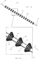
- a surgical suture 100 includes an elongated shaft 102 having a leading end 104 and a trailing 106.
- the elongated shaft is desirably flexible so that the shaft may flex and bend as the surgical suture 100 passes through tissue and/or prosthetic components.
- the surgical suture desirably includes a plurality of flexible protrusions 108 that extend outwardly from the elongated shaft 102. The flexible protrusions are adapted to collapse inwardly toward the shaft as the leading end 104 of the suture is pulled through tissue or a prosthetic device.
- each of the flexible protrusions 108 includes a base 110 adjacent the shaft 102 and a flared ring 112 that is spaced from the outer surface 114 of the shaft 102.
- the diameter of the flared ring 112 is larger than the diameter of the base section 110.
- each of the flexible protrusions 108 has one or more weakened areas 116 formed therein that facilitate flexing or collapsing of the protrusion at the weakened areas.
- the weakened areas 116 are defined by a plurality of pleats that desirably extend between the base 110 and the flared ring 112 of each flexible protrusion 108.
- the weakened areas 116 (e.g. the pleats) provide control over how the flexible protrusion collapses inwardly toward the shaft.
- a plurality of the flexible protrusions may have a similar pattern of weakened areas so that they all collapse inwardly in a particular manner.
- the flexible protrusions 108 are adapted to collapse in a manner similar to an umbrella when the surgical suture is passed in the direction D 1 through tissue during implantation.
- the flexible protrusions provide ease of insertion and minimize resistance as the surgical suture is pulled through the tissue.
- the protrusions 108 engage tissue so as to prevent device reversal in the direction D 2 . If the surgical protrusions are pulled in the opposite direction D 2 , the flexible protrusions 108 engage tissue so as to prevent device reversal through direct interference between the flared edge 112 of the flexible protrusions 108 and the soft tissue.
- the directional interference serves to provide a surgical suture for securing wounds and/or attaching prosthetic devices to soft tissue without requiring additional locking or securing features.
- the flexible protrusions 108 provide holding strength at a plurality of locations along the length of the shaft 102 through the larger diameter flared edge sections 112 of the flexible protrusions 108.
- the spacing between the adjacent flexible protrusions may be modified so that when the flexible protrusions collapse they bridge to the next set of protrusions so that the tissue is dilated and not continually dilating and constricting after each protrusion passes through.
- the flexible protrusions 108 collapse inwardly toward the shaft 102.
- the flexible protrusions 108 collapse in a manner similar to an umbrella whereby they collapse easily in the direction of insertion D 1 , but provide significant holding strength in the opposite direction D 2 .
- the flexible protrusions 108 are linked together by weaker sections to enable the flexible protrusions to collapse easily during insertion into tissue.
- the flexible protrusions include weakened sections that may be formed using slits, hinges, folds, or pleats. The weakened sections of the flexible protrusions may also be formed by thinning sections of the flexible protrusion.
- the flexible protrusions 108 may have a variety of different shapes.
- the surgical suture includes an elongated shaft 102 having a cylindrical shape with conical-shaped flexible protrusions 108 projecting from the shaft.
- other shapes such as flexible protrusions having a bell-like form, an oval shape, a triangular shape and/or a square shape are possible.
- the shaft 102 may have a cross-sectional shape having any one or more of the above-mentioned geometries.
- the surgical suture may include flexible protrusions provided over a portion or the entire length of the shaft 102.
- the surgical suture may be a bi-directional surgical suture including a first set of flexible protrusions oriented in one direction for resisting movement of the shaft in a first direction and a second set of flexible protrusions oriented in an opposite direction for resisting movement of the shaft in a second, opposite direction.
- a surgical suture 100 may be provided as a modular device having a surgical needle attached to each of the leading and trailing ends 104, 106 to aid in passing the device through tissue.
- the surgical suture may be formed from a plurality of materials such as polymers, metals, ceramics, composites, and more preferably, an absorbable or non-absorbable polymeric material. The choice of materials may depend upon the specific surgical application.
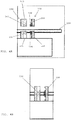
- a method of making surgical sutures having flexible protrusions includes providing a male die 120 having a first clamping part 122 and a second clamping part 124.
- the first clamping part 122 of the male die 120 includes an inner face having a first half of a conical-shaped protrusion 128 projecting therefrom.
- the first clamping part 122 of the male die also includes an outer face.
- the second clamping part 124 of the male die 120 includes an inner face having a second half of a conical-shaped protrusion 134 projecting therefrom.
- the system also preferably includes a female die 138 having a first clamping part 140 and a second clamping part 142.
- the first clamping part 140 of the female die 138 includes an inner face defining a first half of a conical-shaped depression 142.
- the second clamping part 142 of the female die 138 includes an inner face defining a second half of a conical-shaped depression 152.
- the first and second clamping parts of the respective male and female dies 120, 138 may be opened and an elongated shaft 102 is positioned between the first and second clamping parts.
- the opposing clamping parts are closed to engage the outer surface of the shaft 102.
- the male and female dies 124, 138 may be heated to transfer heat to the shaft 102 so that the shaft is heated to a desired temperature for enabling the shaft to be molded by the male and female die.
- the closed male die 124 may be moved in the direction H 1 toward the closed female die 138 to shape a portion of the shaft 102 into a conical-shaped protrusion 108.
- the overall length of the shaft 102 may be shortened.
- the die tooling moves relative to the shaft 102 to compensate for the shortening of the shaft.
- the outer surfaces of the male and female dies that form the flexible protrusions 108 may include folds or perforations that are embossed into the protrusion during a protrusion forming stage. As the closed male die 124 moves toward the closed female die 138 to form the protrusion, folds or perforations may be embossed into the conical-shaped protrusion 108 using the male and female dies.
- the protrusion may be cooled while remaining in contact with the closed male and female dies 124, 138.
- the protrusion may cool after being removed from engagement with the male and female dies.
- the male and female dies 124, 138 may be opened to expose the conical-shaped protrusions 108 to ambient air, preferably for cooling.
- the steps shown in FIGS. 4A-4D may be repeated to form a plurality of flexible protrusions along the length of the shaft 102.
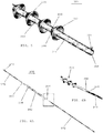
- a surgical suture 200 may include an elongated shaft 202 having a plurality of flexible protrusions 208 projecting therefrom.
- each of the flexible protrusions 208 has a conical shape including a base 210 adjacent an outer surface 214 of the shaft 202 and a flared edge 212 that is spaced from the outer surface 214 of the shaft 202.
- the flared edge section 212 of each protrusion 208 preferably has a larger diameter than the base section 210 of the protrusion.
- the elongated shaft 202 preferably has a lumen 260 formed therein that extends between the ends of the shaft.
- the lumen 260 may define an opening at one of the ends 206 of the elongated shaft 202.
- the lumen 260 may be adapted to receive a filament or monofilament.
- the lumen 260 extends between the trailing end 206 and the leading end (not shown) of the shaft 202.
- the lumen 260 may extend only part way toward the opposite end of the shaft 202.
- the lumen is a blind opening that only extends part way toward the opposite end of the shaft.
- a flowable material such as a pharmacological agent may be introduced into the lumen 260.
- the flowable material may migrate between the trailing end and the leading end of the shaft 202.
- the flowable material may be pre-filled inside the hollow shaft 202 before implanting the surgical suture in tissue.
- an injection tool such as a syringe having a needle may be used for introducing the flowable material into the lumen 260.
- the flowable material may also be introduced after the surgical suture is implanted in tissue.
- the flowable material may be re-introduced into the lumen 260 after implantation. For example, a first dose of pharmacological agent may be introduced when the surgical suture is initially implanted in tissue. After a period of time, one or more additional doses of a pharmacological agent may be introduced into the lumen 260.
- a composite surgical suture 300 includes a tissue anchoring element 200 including an elongated shaft 202 and a plurality of flexible protrusions 208 projecting from the elongated shaft 202.
- a first filament 270 may be secured to the leading end 204 of the tissue anchoring element 200 and a second filament 272 may be secured to the trailing end 206 of the tissue anchoring element 200.
- the trailing end 206 of the tissue anchoring element 200 includes a lumen 260 formed therein.
- the filament 272 is preferably inserted into the lumen for being secured to the trailing end 206 of the tissue anchoring element 200.
- the trailing end of the tissue anchoring element may not have a lumen and the filament may be secured directly to the trailing end of the tissue anchoring element.
- a tissue-piercing element such as a needle (not shown) may be secured to the leading end 275 of the filament 270 for advancing the composite surgical suture 300 through tissue or a prosthetic device.
- the filament may include a plurality of filaments 270, 272. In some embodiments, the filaments may be monofilaments or multifilaments.
- a composite surgical suture 400 includes a first tissue anchoring element 200A and a tissue second anchoring element 200B coupled together by a filament 270 that extends between a trailing end 206A of the first tissue anchoring element 200A and a leading end 204B of the second tissue anchoring element 200B.
- the elongated shafts 202A, 202B of the respective tissue anchoring elements 200A, 200B are hollow and the filament 270 passes completely through the hollow shafts of the two anchoring elements.
- the opposing ends of the elongated shafts 202A, 202B have blind openings or lumens formed therein and smaller segments of filament 270 interconnect the two anchoring elements.
- a first segment 270 of filament interconnects the trailing end 206A of the first anchoring element 200A with the leading end 204B of the second anchoring element 200B.
- a second segment 280 of filament is secured in an opening at a leading end 204A of the first anchoring element 200A, and a third segment 282 of filament is secured to an opening at the trailing end 206B of the second anchoring element 200B.
- the composite surgical suture 400 shown in FIG. 7 preferably provides a multi-part device having one or more sections including flexible protrusions and one or more sections comprising a filament or mutlifilaments.
- the one or more filament sections of the suture may have the same, greater, or less flexibility than the tissue anchoring element sections of the suture.
- the filament portions 270 may be absorbable and the tissue anchoring elements may be non-absorbable.
- the filament sections may be non-absorbable and the anchoring element sections may be absorbable.
- the entire composite surgical suture shown in FIG. 7 may be absorbable or non-absorbable.
- a surgical suture 500 includes an elongated shaft 502 having a plurality of flexible protrusions 508 extending therefrom.
- Each of the flexible protrusions 508 is preferably collapsible inwardly toward the shaft 502.
- Each flexible protrusion 508 desirably includes a base 510 adjacent an outer surface 514 of the shaft 502 and a flared edge 512 spaced from the outer surface of the shaft.
- the flared edge 512 of each protrusion 508 preferably has a larger diameter than the base 510.
- At least one of the flexible protrusions 508 desirably includes an elongated slit 515 formed therein.
- each of the flexible protrusions 508 includes at least one elongated slit 515.
- the elongated slits 515 define straight lines.
- a plurality of elongated slits 515 may be formed around the perimeter of each of the flexible protrusions 508. The elongated slits may be positioned at the same locations on each of the flexible protrusions so that each of the flexible protrusions collapse in a uniform configuration.
- a surgical suture 600 includes an elongated shaft 602 having a plurality of flexible protrusions 608 projecting therefrom.
- Each of the flexible protrusions 608 includes a base 610 adjacent an outer surface of the shaft 608 and a flared edge 612 spaced from the outer surface of the shaft 602.
- at least one of the flexible protrusions 608 includes a curved slit 615 formed therein.
- the curved slit 615 enables the flexible protrusion 608 to more easily collapse inwardly toward the shaft 602.
- each of the flexible protrusions 608 includes at least one of the curved slits 615.
- a plurality of curved slits 615 may be formed in each of the flexible protrusions 608.
- the curved slits 615 may be evenly spaced around the perimeter of the flexible protrusions 608.
- a surgical suture 700 includes an elongated shaft 702 having a leading end 704 and a trailing end 706.
- the surgical suture 700 includes a plurality of flexible protrusions 708 projecting outwardly from the shaft 702.
- each of the flexible protrusions 708 is divided into a plurality of spaced flexible elements 725A-725D having spaces 735A-735D extending between each of the adjacent flexible elements 725A-725D.
- the spaces 735A-735D between the adjacent flexible elements desirably increase the flexibility of the flexible protrusions 708 and reduce the mass passing through the tissue and/or prosthetic devices.
- each of the flexible protrusions 708 includes a plurality of the spaced flexible elements that are spaced from one another around the outer surface of the shaft 702.
- the spaced flexible elements 725A-725D are preferably evenly spaced from one another.
- FIG. 10B four equally spaced flexible sections 725A-725D are shown. In other embodiments, however, a greater number of flexible sections (e.g. six, eight, etc.) may be provided.
- a surgical suture includes a plurality of flexible protrusions 808 provided along the length of an elongated shaft 802.
- Each of the flexible protrusions 808 includes two or more evenly spaced flexible elements 825A-825D that extend around the perimeter of the shaft 802.
- four flexible elements 825A-825D are evenly spaced around the outer surface of the shaft 802.
- web sections 835A-835D extend between the adjacent flexible elements 825A-825D.
- the web sections 835A-835D interconnect the flexible elements 825A-825D, thereby providing flexibility for the flexible elements while coupling the flexible elements together to provide more holding force.
- the web sections 835A-835D may include filaments extending between the adjacent flexible elements 825A-835D.
- the web sections may include mesh or biocompatible mesh extending between the adjacent flexible elements 825A-825D.
- a surgical suture 900 includes an elongated shaft 902 having a plurality of flexible tissue anchoring protrusions 908 projecting therefrom.
- the elongated shaft 902 has a leading end (not shown) and a trailing end 906.
- the surgical suture 900 includes a lumen 960 that extends between the trailing end 906 and the leading end (not shown) of the elongated shaft 902.
- the elongated shaft 902 has an outer surface with a plurality of openings 975 formed therein.
- the plurality of openings 975 are preferably in communication with the lumen 960 extending along the length of the shaft 902.
- a flowable material such as a pharmacological agent may be introduced into the lumen 960.
- the flowable material When the surgical suture 900 is implanted in tissue or in a prosthetic device, the flowable material preferably flows from the lumen and through the plurality of opening 975 extending along the length of the shaft 902.
- the plurality of openings 975 extending through the outer wall of the shaft 902 allows delivery of the flowable material to the tissue and/or the prosthetic device surrounding the suture.
- the flowable material may be pre-filled inside the elongated opening 960 as the surgical suture is initially implanted in the tissue and/or the prosthetic device.
- the flowable material may also be introduced into the elongated opening after the surgical suture has been implanted.
- additional doses of the flowable material may be introduced into the lumen 960 for delivery through the plurality of openings 975 extending along the length of the elongated shaft 902.
- the additional doses of the flowable material may be introduced after implantation of the surgical suture in tissue.
Landscapes
- Health & Medical Sciences (AREA)
- Life Sciences & Earth Sciences (AREA)
- Surgery (AREA)
- Heart & Thoracic Surgery (AREA)
- Engineering & Computer Science (AREA)
- Biomedical Technology (AREA)
- Nuclear Medicine, Radiotherapy & Molecular Imaging (AREA)
- Medical Informatics (AREA)
- Molecular Biology (AREA)
- Animal Behavior & Ethology (AREA)
- General Health & Medical Sciences (AREA)
- Public Health (AREA)
- Veterinary Medicine (AREA)
- Materials For Medical Uses (AREA)
- Surgical Instruments (AREA)
Claims (14)
- Chirurgisches Nahtmaterial (200, 100), umfassend:einen Schaft (202, 102) mit einem vorderen Ende (204, 104), einem hinteren Ende (206, 106) und einem Lumen (260), das sich zwischen dem vorderen (204, 104) und dem hinteren (206, 106) Ende erstreckt,eine Vielzahl von flexiblen Vorsprüngen (208, 108), die sich vom Schaft (202, 102) erstrecken, und mindestens ein Filament (270, 272), das sich durch das Lumen (260) erstreckt,dadurch gekennzeichnet, dass jeder der flexiblen Vorsprünge der Vielzahl von flexiblen Vorsprüngen (208, 108) eine dem Schaft (102) benachbarte Basis (110) und einen von der Außenfläche (114) des Schafts beabstandeten aufgeweiteten Ring (112) aufweist.
- Chirurgisches Nahtmaterial (200, 100) nach Anspruch 1, wobei die flexiblen Vorsprünge eine konische, glockenförmige, ovale, dreieckige oder quadratische Form haben.
- Chirurgisches Nahtmaterial (200) nach Anspruch 1, wobei der Schaft (202) oder das mindestens eine Filament (270, 272) absorbierbar ist.
- Chirurgisches Nahtmaterial (200) nach Anspruch 1, wobei das mindestens eine Filament (270, 272) flexibler als der Schaft (202) ist.
- Chirurgisches Nahtmaterial (200) nach Anspruch 1, wobei das Lumen (260) in dem Schaft (202) angeordnet und geeignet ist, ein fließfähiges Material aufzunehmen.
- Chirurgisches Nahtmaterial (900) nach Anspruch 5, wobei der Schaft (902) eine Außenfläche, die sich zwischen dem vorderen und dem hinteren Ende davon erstreckt, und eine Vielzahl von sich durch die Außenfläche erstreckenden Öffnungen (975) hat, die mit dem Lumen (960) kommunizieren.
- Chirurgisches Nahtmaterial (900) nach Anspruch 6, ferner umfassend ein in dem Lumen (960) angeordnetes fließfähiges Material, wobei das fließfähige Material geeignet ist, von dem Lumen (960) und durch die Vielzahl von Öffnungen (975) in der Außenfläche des Schafts zu gehen.
- Chirurgisches Nahtmaterial (900) nach Anspruch 7, wobei das fließfähige Material aus der Gruppe fließfähiger Materialien, die aus Pharmakologika, Klebstoffen, Epoxiden und Polymeren besteht, ausgewählt ist.
- Chirurgisches Nahtmaterial (700, 800) nach Anspruch 1, wobei mindestens einer der flexiblen Vorsprünge (708) in zwei oder mehr flexible Elemente (725A - 725D), die um den Schaft (702) herum gleichmäßig voneinander beabstandet sind, geteilt ist.
- Chirurgisches Nahtmaterial (800) nach Anspruch 9, wobei die flexiblen Elemente (825A - 825D) gegenüberliegende Ränder haben und sich mindestens ein Steg (835A - 835D) zwischen mindestens zweien der gegenüberliegenden Ränder erstreckt.
- Chirurgisches Nahtmaterial (802) nach Anspruch 10, wobei der mindestens eine Steg (835A - 835D) aus einer Gruppe von Materialien, die aus Netz, Gewebe, Anbindungen, Garn und Filamenten besteht, ausgewählt ist.
- Chirurgisches Nahtmaterial nach Anspruch 6, ferner umfassend eine erste axiale Öffnung, die am vorderen Ende des Schafts vorgesehen ist, und eine zweite axiale Öffnung, die am hinteren Ende des Schafts vorgesehen ist, wobei die erste und die zweite axiale Öffnung mit dem Lumen (260) kommunizieren.
- Chirurgisches Nahtmaterial nach Anspruch 12, ferner umfassend ein fließfähiges Material, das durch die erste oder die zweite axiale Öffnung und in das Lumen einführbar ist, wobei das fließfähige Material geeignet ist, durch die Vielzahl von Öffnungen (960) in der Außenfläche des Schafts zu gehen.
- Chirurgisches Nahtmaterial nach Anspruch 1, wobei das Filament (270, 272) an dem Schaft befestigt ist.
Applications Claiming Priority (2)
| Application Number | Priority Date | Filing Date | Title |
|---|---|---|---|
| US12/340,829 US8226684B2 (en) | 2008-12-22 | 2008-12-22 | Surgical sutures having collapsible tissue anchoring protrusions and methods therefor |
| PCT/US2009/065350 WO2010074861A1 (en) | 2008-12-22 | 2009-11-20 | Surgical sutures having collapsible tissue anchoring protrusions and methods therefor |
Publications (2)
| Publication Number | Publication Date |
|---|---|
| EP2373229A1 EP2373229A1 (de) | 2011-10-12 |
| EP2373229B1 true EP2373229B1 (de) | 2017-03-29 |
Family
ID=41667212
Family Applications (1)
| Application Number | Title | Priority Date | Filing Date |
|---|---|---|---|
| EP09801601.7A Not-in-force EP2373229B1 (de) | 2008-12-22 | 2009-11-20 | Chirurgisches nahtmaterial mit kollabierbaren gewebeverankerungsvorsprüngen und verfahren dafür |
Country Status (4)
| Country | Link |
|---|---|
| US (1) | US8226684B2 (de) |
| EP (1) | EP2373229B1 (de) |
| ES (1) | ES2625942T3 (de) |
| WO (1) | WO2010074861A1 (de) |
Families Citing this family (55)
| Publication number | Priority date | Publication date | Assignee | Title |
|---|---|---|---|---|
| US5931855A (en) | 1997-05-21 | 1999-08-03 | Frank Hoffman | Surgical methods using one-way suture |
| CN101431947A (zh) | 2004-05-14 | 2009-05-13 | 奎尔医疗公司 | 缝合方法和器械 |
| US20080255612A1 (en) * | 2007-04-13 | 2008-10-16 | Angiotech Pharmaceuticals, Inc. | Self-retaining systems for surgical procedures |
| EP2550978B1 (de) * | 2007-09-27 | 2014-04-30 | Ethicon, LLC | Vorrichtung zum Scheiden von Widerhaken auf einer Naht |
| BRPI0820129B8 (pt) | 2007-12-19 | 2021-06-22 | Angiotech Pharm Inc | processo de formação de uma sutura autorretentora e sutura autorretentora |
| US8916077B1 (en) | 2007-12-19 | 2014-12-23 | Ethicon, Inc. | Self-retaining sutures with retainers formed from molten material |
| US8118834B1 (en) | 2007-12-20 | 2012-02-21 | Angiotech Pharmaceuticals, Inc. | Composite self-retaining sutures and method |
| WO2009089101A2 (en) * | 2008-01-03 | 2009-07-16 | Wilson-Cook Medical, Inc. | Medical systems, devices and methods for endoscopically suturing perforations |
| WO2009097556A2 (en) | 2008-01-30 | 2009-08-06 | Angiotech Pharmaceuticals, Inc. | Appartaus and method for forming self-retaining sutures |
| US8615856B1 (en) | 2008-01-30 | 2013-12-31 | Ethicon, Inc. | Apparatus and method for forming self-retaining sutures |
| WO2009105663A2 (en) | 2008-02-21 | 2009-08-27 | Angiotech Pharmaceuticals, Inc. | Method and apparatus for elevating retainers on self-retaining sutures |
| US8641732B1 (en) | 2008-02-26 | 2014-02-04 | Ethicon, Inc. | Self-retaining suture with variable dimension filament and method |
| WO2009129251A2 (en) * | 2008-04-15 | 2009-10-22 | Angiotech Pharmaceuticals, Inc. | Self-retaining sutures with bi-directional retainers or uni-directional retainers |
| MX339174B (es) | 2008-11-03 | 2016-05-12 | Ethicon Llc | Longitud de sutura autorretenible y metodo y dispositivo para su uso. |
| US8517073B2 (en) * | 2009-07-16 | 2013-08-27 | Covidien Lp | Apparatus and method for joining similar or dissimilar suture products |
| US9011487B2 (en) * | 2009-08-27 | 2015-04-21 | Ethicon, Inc. | Barbed sutures having pledget stoppers and methods therefor |
| US8210085B2 (en) * | 2009-08-27 | 2012-07-03 | Ethicon, Inc. | Automated systems and methods for making braided barbed sutures |
| WO2011090628A2 (en) | 2009-12-29 | 2011-07-28 | Angiotech Pharmaceuticals, Inc. | Bidirectional self-retaining sutures with laser-marked and/or non-laser marked indicia and methods |
| KR101883143B1 (ko) | 2010-05-04 | 2018-07-31 | 에티컨, 엘엘씨 | 자가-유지형 봉합재를 생성하기 위한 레이저 커팅 시스템 및 방법 |
| AU2011265232B2 (en) | 2010-06-11 | 2015-01-22 | Ethicon Llc | Suture delivery tools for endoscopic and robot-assisted surgery and methods |
| US8398679B2 (en) * | 2010-10-28 | 2013-03-19 | Covidien Lp | Modular suture |
| CA2816326C (en) * | 2010-11-03 | 2020-12-15 | Ethicon, Llc | Drug-eluting self-retaining sutures and methods relating thereto |
| MX342984B (es) | 2010-11-09 | 2016-10-19 | Ethicon Llc | Suturas de autorretencion de emergencia y envasado de estas. |
| KR101132841B1 (ko) | 2011-03-07 | 2012-04-02 | 김영재 | 봉합사 |
| WO2012129534A2 (en) | 2011-03-23 | 2012-09-27 | Angiotech Pharmaceuticals, Inc. | Self-retaining variable loop sutures |
| KR101256908B1 (ko) | 2011-04-28 | 2013-04-23 | (주)에이치비메디컬스 | 주름제거용 충전체 |
| US20130172931A1 (en) | 2011-06-06 | 2013-07-04 | Jeffrey M. Gross | Methods and devices for soft palate tissue elevation procedures |
| KR101185583B1 (ko) | 2011-12-27 | 2012-09-24 | 김영재 | 매듭짓는 작업이 필요 없는 봉합사 및 이를 포함하는 키트 |
| US20130231699A1 (en) * | 2012-02-20 | 2013-09-05 | Dr7 Innovations, Llc | Locking suture |
| KR101362446B1 (ko) * | 2012-05-10 | 2014-02-11 | 이훈범 | 주름제거용 충전체 |
| USD690810S1 (en) * | 2012-09-17 | 2013-10-01 | Ethicon, Inc. | Surgical suture |
| US10010317B2 (en) | 2012-12-05 | 2018-07-03 | Young Jae Kim | Method of improving elasticity of tissue of living body |
| US10178990B2 (en) | 2012-12-05 | 2019-01-15 | Y. Jacobs Medical Inc. | Apparatus for inserting surgical thread, and surgical procedure kit for inserting surgical thread comprising same |
| US9597426B2 (en) | 2013-01-25 | 2017-03-21 | Covidien Lp | Hydrogel filled barbed suture |
| US9872679B2 (en) | 2013-02-05 | 2018-01-23 | Ethicon, Inc. | Locally reversible barbed sutures |
| US10350094B2 (en) | 2013-03-11 | 2019-07-16 | Microvention, Inc. | Implantable device with adhesive properties |
| US9044301B1 (en) * | 2013-11-25 | 2015-06-02 | Innfocus, Inc. | Methods, systems and devices for treating glaucoma |
| WO2015083864A1 (ko) * | 2013-12-06 | 2015-06-11 | 주식회사 와이제이콥스메디칼 | 의료용 관 삽입 장치 및 이를 구비한 의료용 관 삽입 시술 키트 |
| WO2015171962A1 (en) * | 2014-05-07 | 2015-11-12 | Bart Bracy | Multipart suture |
| KR101701434B1 (ko) * | 2015-11-18 | 2017-02-13 | 정영춘 | 신규 안면 및 신체 리프팅용 봉합사 |
| US10258326B2 (en) | 2016-02-08 | 2019-04-16 | Ethicon, Inc. | Elastic tissue reinforcing fastener |
| KR20190031859A (ko) * | 2017-09-18 | 2019-03-27 | 21세기메디칼 주식회사 | 리테이너를 갖는 생분해성 봉합사 및 그의 제조방법 |
| KR102184638B1 (ko) * | 2018-05-18 | 2020-11-30 | (주)제이월드 | 의료용 봉합사 및 의료용 봉합사 키트 |
| CN110123485B (zh) * | 2019-06-19 | 2024-05-28 | 童妍(上海)医疗器械有限公司 | 一种单向提拉埋植线、提拉装置及使用其的整形方法 |
| USD905243S1 (en) * | 2019-07-18 | 2020-12-15 | Medi Futures Co., Ltd. | Medical thread |
| USD905244S1 (en) * | 2019-07-18 | 2020-12-15 | Medi Futures Co., Ltd. | Medical thread |
| AU2020344233B2 (en) * | 2019-09-13 | 2024-01-04 | Ethicon, Inc. | Barbed microcatheters having fluid egress openings for infusing therapeutic fluids into tissue and methods of making and using the same |
| USD903855S1 (en) | 2019-09-13 | 2020-12-01 | Ethicon, Inc. | Barbed microcatheter with spaced round openings |
| USD904603S1 (en) | 2019-09-13 | 2020-12-08 | Ethicon, Inc. | Barbed microcatheter with spaced elongated slits |
| US11129968B2 (en) * | 2019-09-13 | 2021-09-28 | Ethicon, Inc. | Methods of making and implanting barbed microcatheters having fluid egress openings for infusing therapeutic fluids |
| USD936829S1 (en) * | 2019-12-13 | 2021-11-23 | Samyang Holdings Corporation | Medical thread |
| US20210290223A1 (en) * | 2020-01-21 | 2021-09-23 | Zelegent, Inc. | Device and methods for use in robotic assisted surgery for treatment of obstructive sleep apnea |
| AU2020294238A1 (en) * | 2020-05-15 | 2021-12-02 | Clayton L. Moliver | Knotless sutures including integrated closures |
| US11826041B2 (en) * | 2021-02-12 | 2023-11-28 | Washington University | Barbed rod for linear tissue closure and approximation |
| KR102469897B1 (ko) * | 2022-03-15 | 2022-11-23 | 박남진 | 의료용 봉합사, 그 제조방법 및 장치 |
Citations (1)
| Publication number | Priority date | Publication date | Assignee | Title |
|---|---|---|---|---|
| WO2010052006A1 (en) * | 2008-11-06 | 2010-05-14 | Aesculap Ag | Medical product, a surgical kit, and a method for producing the medical product |
Family Cites Families (23)
| Publication number | Priority date | Publication date | Assignee | Title |
|---|---|---|---|---|
| US522976A (en) * | 1894-07-17 | Carriage | ||
| US3123077A (en) * | 1964-03-03 | Surgical suture | ||
| US3570497A (en) * | 1969-01-16 | 1971-03-16 | Gerald M Lemole | Suture apparatus and methods |
| JPS5315191Y2 (de) | 1975-11-17 | 1978-04-21 | ||
| US4952585A (en) * | 1988-12-15 | 1990-08-28 | Merrell Dow Pharmaceuticals Inc. | Castanospermine esters in the inhibition of tumor metastasis |
| US5222976A (en) | 1989-05-16 | 1993-06-29 | Inbae Yoon | Suture devices particularly useful in endoscopic surgery |
| US5053047A (en) * | 1989-05-16 | 1991-10-01 | Inbae Yoon | Suture devices particularly useful in endoscopic surgery and methods of suturing |
| US4950285A (en) | 1989-11-27 | 1990-08-21 | Wilk Peter J | Suture device |
| DE4302895C2 (de) | 1993-02-02 | 1996-03-28 | Wiessner Serag Gmbh & Co Kg | Chirurgischer Faden |
| US5500000A (en) * | 1993-07-01 | 1996-03-19 | United States Surgical Corporation | Soft tissue repair system and method |
| CA2117967A1 (en) * | 1993-10-27 | 1995-04-28 | Thomas W. Sander | Tissue repair device and apparatus and method for fabricating same |
| JP3334485B2 (ja) | 1996-04-30 | 2002-10-15 | アイシン・エィ・ダブリュ株式会社 | 自動変速機の油圧制御装置 |
| EP1079740B1 (de) * | 1998-05-21 | 2007-08-29 | Christopher J. Walshe | System zum fixieren von gewebe |
| US6712859B2 (en) * | 2001-06-28 | 2004-03-30 | Ethicon, Inc. | Hernia repair prosthesis and methods for making same |
| US6971813B2 (en) * | 2002-09-27 | 2005-12-06 | Labcoat, Ltd. | Contact coating of prostheses |
| US7021316B2 (en) * | 2003-08-07 | 2006-04-04 | Tools For Surgery, Llc | Device and method for tacking a prosthetic screen |
| AU2004296810B2 (en) | 2003-12-04 | 2009-11-19 | Ethicon, Inc. | Active suture for the delivery of therapeutic fluids |
| US7468068B2 (en) * | 2004-06-30 | 2008-12-23 | Alwin Kolster | Suture for wound closure, tissue approximation, tissue support, suspension and/or fixation |
| TW200608109A (en) * | 2004-08-31 | 2006-03-01 | Ind Tech Res Inst | Transflective LCD element and the manufacturing method of the same |
| AU2005295811B2 (en) | 2004-10-18 | 2011-03-03 | Covidien Lp | Adhesive suture structure and methods of using the same |
| US7758594B2 (en) * | 2005-05-20 | 2010-07-20 | Neotract, Inc. | Devices, systems and methods for treating benign prostatic hyperplasia and other conditions |
| US8663277B2 (en) * | 2005-06-29 | 2014-03-04 | Ethicon, Inc. | Braided barbed suture |
| FR2914178B1 (fr) | 2007-03-27 | 2010-05-14 | Cie De Rech En Composants Impl | Prothese implantable de renfort avec des moyens de fixation |
-
2008
- 2008-12-22 US US12/340,829 patent/US8226684B2/en not_active Expired - Fee Related
-
2009
- 2009-11-20 EP EP09801601.7A patent/EP2373229B1/de not_active Not-in-force
- 2009-11-20 ES ES09801601.7T patent/ES2625942T3/es active Active
- 2009-11-20 WO PCT/US2009/065350 patent/WO2010074861A1/en not_active Ceased
Patent Citations (1)
| Publication number | Priority date | Publication date | Assignee | Title |
|---|---|---|---|---|
| WO2010052006A1 (en) * | 2008-11-06 | 2010-05-14 | Aesculap Ag | Medical product, a surgical kit, and a method for producing the medical product |
Also Published As
| Publication number | Publication date |
|---|---|
| EP2373229A1 (de) | 2011-10-12 |
| US8226684B2 (en) | 2012-07-24 |
| US20100160961A1 (en) | 2010-06-24 |
| ES2625942T3 (es) | 2017-07-21 |
| WO2010074861A8 (en) | 2011-06-23 |
| WO2010074861A1 (en) | 2010-07-01 |
Similar Documents
| Publication | Publication Date | Title |
|---|---|---|
| US8226684B2 (en) | Surgical sutures having collapsible tissue anchoring protrusions and methods therefor | |
| EP2288295B1 (de) | Faltbare widerhakennaht mit reduzierter zugkraft | |
| US8821539B2 (en) | Collapsible barbed sutures having reduced drag and methods therefor | |
| KR101224369B1 (ko) | 꼬인 미늘형 봉합사 | |
| EP3202336B1 (de) | Elastisches befestigungsmittel zur verstärkung eines gewebes | |
| US4736746A (en) | Method of fastening tissues | |
| RU2724438C2 (ru) | Локально реверсивные шовные нити с зазубринами | |
| AU2005287010B2 (en) | Gastrointestinal anchor | |
| CN110099610B (zh) | 针与网状缝线的间接附接 | |
| CN104224253A (zh) | 缝合方法和器械 | |
| AU2023266334A1 (en) | Continuous tethered tissue anchor and associated systems and methods | |
| US11547397B2 (en) | Devices, systems, and methods for repairing soft tissue and attaching soft tissue to bone | |
| KR101176154B1 (ko) | 관강내 수술용 전달 시스템 | |
| JP2009261934A (ja) | 統合貫通端を有する組織を接合するための装置 | |
| US20230233200A1 (en) | Devices, systems, and methods for repairing soft tissue and attaching soft tissue to bone |
Legal Events
| Date | Code | Title | Description |
|---|---|---|---|
| PUAI | Public reference made under article 153(3) epc to a published international application that has entered the european phase |
Free format text: ORIGINAL CODE: 0009012 |
|
| 17P | Request for examination filed |
Effective date: 20110705 |
|
| AK | Designated contracting states |
Kind code of ref document: A1 Designated state(s): AT BE BG CH CY CZ DE DK EE ES FI FR GB GR HR HU IE IS IT LI LT LU LV MC MK MT NL NO PL PT RO SE SI SK SM TR |
|
| DAX | Request for extension of the european patent (deleted) | ||
| 17Q | First examination report despatched |
Effective date: 20150130 |
|
| GRAP | Despatch of communication of intention to grant a patent |
Free format text: ORIGINAL CODE: EPIDOSNIGR1 |
|
| INTG | Intention to grant announced |
Effective date: 20160707 |
|
| GRAJ | Information related to disapproval of communication of intention to grant by the applicant or resumption of examination proceedings by the epo deleted |
Free format text: ORIGINAL CODE: EPIDOSDIGR1 |
|
| GRAP | Despatch of communication of intention to grant a patent |
Free format text: ORIGINAL CODE: EPIDOSNIGR1 |
|
| INTC | Intention to grant announced (deleted) | ||
| INTG | Intention to grant announced |
Effective date: 20161214 |
|
| GRAS | Grant fee paid |
Free format text: ORIGINAL CODE: EPIDOSNIGR3 |
|
| GRAA | (expected) grant |
Free format text: ORIGINAL CODE: 0009210 |
|
| AK | Designated contracting states |
Kind code of ref document: B1 Designated state(s): AT BE BG CH CY CZ DE DK EE ES FI FR GB GR HR HU IE IS IT LI LT LU LV MC MK MT NL NO PL PT RO SE SI SK SM TR |
|
| REG | Reference to a national code |
Ref country code: GB Ref legal event code: FG4D |
|
| REG | Reference to a national code |
Ref country code: CH Ref legal event code: EP |
|
| REG | Reference to a national code |
Ref country code: AT Ref legal event code: REF Ref document number: 879006 Country of ref document: AT Kind code of ref document: T Effective date: 20170415 |
|
| REG | Reference to a national code |
Ref country code: IE Ref legal event code: FG4D |
|
| REG | Reference to a national code |
Ref country code: DE Ref legal event code: R096 Ref document number: 602009045122 Country of ref document: DE |
|
| REG | Reference to a national code |
Ref country code: ES Ref legal event code: FG2A Ref document number: 2625942 Country of ref document: ES Kind code of ref document: T3 Effective date: 20170721 |
|
| PG25 | Lapsed in a contracting state [announced via postgrant information from national office to epo] |
Ref country code: HR Free format text: LAPSE BECAUSE OF FAILURE TO SUBMIT A TRANSLATION OF THE DESCRIPTION OR TO PAY THE FEE WITHIN THE PRESCRIBED TIME-LIMIT Effective date: 20170329 Ref country code: LT Free format text: LAPSE BECAUSE OF FAILURE TO SUBMIT A TRANSLATION OF THE DESCRIPTION OR TO PAY THE FEE WITHIN THE PRESCRIBED TIME-LIMIT Effective date: 20170329 Ref country code: GR Free format text: LAPSE BECAUSE OF FAILURE TO SUBMIT A TRANSLATION OF THE DESCRIPTION OR TO PAY THE FEE WITHIN THE PRESCRIBED TIME-LIMIT Effective date: 20170630 Ref country code: FI Free format text: LAPSE BECAUSE OF FAILURE TO SUBMIT A TRANSLATION OF THE DESCRIPTION OR TO PAY THE FEE WITHIN THE PRESCRIBED TIME-LIMIT Effective date: 20170329 Ref country code: NO Free format text: LAPSE BECAUSE OF FAILURE TO SUBMIT A TRANSLATION OF THE DESCRIPTION OR TO PAY THE FEE WITHIN THE PRESCRIBED TIME-LIMIT Effective date: 20170629 |
|
| REG | Reference to a national code |
Ref country code: NL Ref legal event code: MP Effective date: 20170329 |
|
| REG | Reference to a national code |
Ref country code: AT Ref legal event code: MK05 Ref document number: 879006 Country of ref document: AT Kind code of ref document: T Effective date: 20170329 |
|
| PG25 | Lapsed in a contracting state [announced via postgrant information from national office to epo] |
Ref country code: BG Free format text: LAPSE BECAUSE OF FAILURE TO SUBMIT A TRANSLATION OF THE DESCRIPTION OR TO PAY THE FEE WITHIN THE PRESCRIBED TIME-LIMIT Effective date: 20170629 Ref country code: SE Free format text: LAPSE BECAUSE OF FAILURE TO SUBMIT A TRANSLATION OF THE DESCRIPTION OR TO PAY THE FEE WITHIN THE PRESCRIBED TIME-LIMIT Effective date: 20170329 Ref country code: LV Free format text: LAPSE BECAUSE OF FAILURE TO SUBMIT A TRANSLATION OF THE DESCRIPTION OR TO PAY THE FEE WITHIN THE PRESCRIBED TIME-LIMIT Effective date: 20170329 |
|
| PG25 | Lapsed in a contracting state [announced via postgrant information from national office to epo] |
Ref country code: NL Free format text: LAPSE BECAUSE OF FAILURE TO SUBMIT A TRANSLATION OF THE DESCRIPTION OR TO PAY THE FEE WITHIN THE PRESCRIBED TIME-LIMIT Effective date: 20170329 |
|
| REG | Reference to a national code |
Ref country code: FR Ref legal event code: PLFP Year of fee payment: 9 |
|
| PG25 | Lapsed in a contracting state [announced via postgrant information from national office to epo] |
Ref country code: EE Free format text: LAPSE BECAUSE OF FAILURE TO SUBMIT A TRANSLATION OF THE DESCRIPTION OR TO PAY THE FEE WITHIN THE PRESCRIBED TIME-LIMIT Effective date: 20170329 Ref country code: SK Free format text: LAPSE BECAUSE OF FAILURE TO SUBMIT A TRANSLATION OF THE DESCRIPTION OR TO PAY THE FEE WITHIN THE PRESCRIBED TIME-LIMIT Effective date: 20170329 Ref country code: RO Free format text: LAPSE BECAUSE OF FAILURE TO SUBMIT A TRANSLATION OF THE DESCRIPTION OR TO PAY THE FEE WITHIN THE PRESCRIBED TIME-LIMIT Effective date: 20170329 Ref country code: AT Free format text: LAPSE BECAUSE OF FAILURE TO SUBMIT A TRANSLATION OF THE DESCRIPTION OR TO PAY THE FEE WITHIN THE PRESCRIBED TIME-LIMIT Effective date: 20170329 Ref country code: CZ Free format text: LAPSE BECAUSE OF FAILURE TO SUBMIT A TRANSLATION OF THE DESCRIPTION OR TO PAY THE FEE WITHIN THE PRESCRIBED TIME-LIMIT Effective date: 20170329 |
|
| PG25 | Lapsed in a contracting state [announced via postgrant information from national office to epo] |
Ref country code: PT Free format text: LAPSE BECAUSE OF FAILURE TO SUBMIT A TRANSLATION OF THE DESCRIPTION OR TO PAY THE FEE WITHIN THE PRESCRIBED TIME-LIMIT Effective date: 20170731 Ref country code: SM Free format text: LAPSE BECAUSE OF FAILURE TO SUBMIT A TRANSLATION OF THE DESCRIPTION OR TO PAY THE FEE WITHIN THE PRESCRIBED TIME-LIMIT Effective date: 20170329 Ref country code: PL Free format text: LAPSE BECAUSE OF FAILURE TO SUBMIT A TRANSLATION OF THE DESCRIPTION OR TO PAY THE FEE WITHIN THE PRESCRIBED TIME-LIMIT Effective date: 20170329 Ref country code: IS Free format text: LAPSE BECAUSE OF FAILURE TO SUBMIT A TRANSLATION OF THE DESCRIPTION OR TO PAY THE FEE WITHIN THE PRESCRIBED TIME-LIMIT Effective date: 20170729 |
|
| REG | Reference to a national code |
Ref country code: DE Ref legal event code: R097 Ref document number: 602009045122 Country of ref document: DE |
|
| PG25 | Lapsed in a contracting state [announced via postgrant information from national office to epo] |
Ref country code: DK Free format text: LAPSE BECAUSE OF FAILURE TO SUBMIT A TRANSLATION OF THE DESCRIPTION OR TO PAY THE FEE WITHIN THE PRESCRIBED TIME-LIMIT Effective date: 20170329 |
|
| PLBE | No opposition filed within time limit |
Free format text: ORIGINAL CODE: 0009261 |
|
| STAA | Information on the status of an ep patent application or granted ep patent |
Free format text: STATUS: NO OPPOSITION FILED WITHIN TIME LIMIT |
|
| 26N | No opposition filed |
Effective date: 20180103 |
|
| PG25 | Lapsed in a contracting state [announced via postgrant information from national office to epo] |
Ref country code: SI Free format text: LAPSE BECAUSE OF FAILURE TO SUBMIT A TRANSLATION OF THE DESCRIPTION OR TO PAY THE FEE WITHIN THE PRESCRIBED TIME-LIMIT Effective date: 20170329 |
|
| PG25 | Lapsed in a contracting state [announced via postgrant information from national office to epo] |
Ref country code: MC Free format text: LAPSE BECAUSE OF FAILURE TO SUBMIT A TRANSLATION OF THE DESCRIPTION OR TO PAY THE FEE WITHIN THE PRESCRIBED TIME-LIMIT Effective date: 20170329 |
|
| PG25 | Lapsed in a contracting state [announced via postgrant information from national office to epo] |
Ref country code: LI Free format text: LAPSE BECAUSE OF NON-PAYMENT OF DUE FEES Effective date: 20171130 Ref country code: CH Free format text: LAPSE BECAUSE OF NON-PAYMENT OF DUE FEES Effective date: 20171130 |
|
| PG25 | Lapsed in a contracting state [announced via postgrant information from national office to epo] |
Ref country code: LU Free format text: LAPSE BECAUSE OF NON-PAYMENT OF DUE FEES Effective date: 20171120 |
|
| REG | Reference to a national code |
Ref country code: BE Ref legal event code: MM Effective date: 20171130 |
|
| PG25 | Lapsed in a contracting state [announced via postgrant information from national office to epo] |
Ref country code: MT Free format text: LAPSE BECAUSE OF NON-PAYMENT OF DUE FEES Effective date: 20171120 |
|
| REG | Reference to a national code |
Ref country code: FR Ref legal event code: PLFP Year of fee payment: 10 |
|
| PG25 | Lapsed in a contracting state [announced via postgrant information from national office to epo] |
Ref country code: BE Free format text: LAPSE BECAUSE OF NON-PAYMENT OF DUE FEES Effective date: 20171130 |
|
| PG25 | Lapsed in a contracting state [announced via postgrant information from national office to epo] |
Ref country code: HU Free format text: LAPSE BECAUSE OF FAILURE TO SUBMIT A TRANSLATION OF THE DESCRIPTION OR TO PAY THE FEE WITHIN THE PRESCRIBED TIME-LIMIT; INVALID AB INITIO Effective date: 20091120 |
|
| PG25 | Lapsed in a contracting state [announced via postgrant information from national office to epo] |
Ref country code: CY Free format text: LAPSE BECAUSE OF NON-PAYMENT OF DUE FEES Effective date: 20170329 |
|
| PG25 | Lapsed in a contracting state [announced via postgrant information from national office to epo] |
Ref country code: MK Free format text: LAPSE BECAUSE OF FAILURE TO SUBMIT A TRANSLATION OF THE DESCRIPTION OR TO PAY THE FEE WITHIN THE PRESCRIBED TIME-LIMIT Effective date: 20170329 |
|
| PGFP | Annual fee paid to national office [announced via postgrant information from national office to epo] |
Ref country code: IE Payment date: 20191111 Year of fee payment: 11 |
|
| PGFP | Annual fee paid to national office [announced via postgrant information from national office to epo] |
Ref country code: ES Payment date: 20191202 Year of fee payment: 11 |
|
| PG25 | Lapsed in a contracting state [announced via postgrant information from national office to epo] |
Ref country code: TR Free format text: LAPSE BECAUSE OF FAILURE TO SUBMIT A TRANSLATION OF THE DESCRIPTION OR TO PAY THE FEE WITHIN THE PRESCRIBED TIME-LIMIT Effective date: 20170329 |
|
| PGFP | Annual fee paid to national office [announced via postgrant information from national office to epo] |
Ref country code: IT Payment date: 20201013 Year of fee payment: 12 Ref country code: GB Payment date: 20201111 Year of fee payment: 12 Ref country code: FR Payment date: 20201013 Year of fee payment: 12 |
|
| PG25 | Lapsed in a contracting state [announced via postgrant information from national office to epo] |
Ref country code: IE Free format text: LAPSE BECAUSE OF NON-PAYMENT OF DUE FEES Effective date: 20201120 |
|
| REG | Reference to a national code |
Ref country code: ES Ref legal event code: FD2A Effective date: 20220202 |
|
| PG25 | Lapsed in a contracting state [announced via postgrant information from national office to epo] |
Ref country code: ES Free format text: LAPSE BECAUSE OF NON-PAYMENT OF DUE FEES Effective date: 20201121 |
|
| GBPC | Gb: european patent ceased through non-payment of renewal fee |
Effective date: 20211120 |
|
| PG25 | Lapsed in a contracting state [announced via postgrant information from national office to epo] |
Ref country code: GB Free format text: LAPSE BECAUSE OF NON-PAYMENT OF DUE FEES Effective date: 20211120 |
|
| PG25 | Lapsed in a contracting state [announced via postgrant information from national office to epo] |
Ref country code: FR Free format text: LAPSE BECAUSE OF NON-PAYMENT OF DUE FEES Effective date: 20211130 |
|
| PG25 | Lapsed in a contracting state [announced via postgrant information from national office to epo] |
Ref country code: IT Free format text: LAPSE BECAUSE OF NON-PAYMENT OF DUE FEES Effective date: 20211120 |
|
| PGFP | Annual fee paid to national office [announced via postgrant information from national office to epo] |
Ref country code: DE Payment date: 20220621 Year of fee payment: 14 |
|
| REG | Reference to a national code |
Ref country code: DE Ref legal event code: R119 Ref document number: 602009045122 Country of ref document: DE |
|
| PG25 | Lapsed in a contracting state [announced via postgrant information from national office to epo] |
Ref country code: DE Free format text: LAPSE BECAUSE OF NON-PAYMENT OF DUE FEES Effective date: 20240601 |
|
| PG25 | Lapsed in a contracting state [announced via postgrant information from national office to epo] |
Ref country code: DE Free format text: LAPSE BECAUSE OF NON-PAYMENT OF DUE FEES Effective date: 20240601 |