EP2373575B1 - Verfahren und ausrüstung zur herstellung von ammoniak-zusatz-syngas mit einer lufttrennungseinheit als stickstoffquelle - Google Patents
Verfahren und ausrüstung zur herstellung von ammoniak-zusatz-syngas mit einer lufttrennungseinheit als stickstoffquelle Download PDFInfo
- Publication number
- EP2373575B1 EP2373575B1 EP09783903.9A EP09783903A EP2373575B1 EP 2373575 B1 EP2373575 B1 EP 2373575B1 EP 09783903 A EP09783903 A EP 09783903A EP 2373575 B1 EP2373575 B1 EP 2373575B1
- Authority
- EP
- European Patent Office
- Prior art keywords
- reformer
- syngas
- additional
- stream
- primary
- Prior art date
- Legal status (The legal status is an assumption and is not a legal conclusion. Google has not performed a legal analysis and makes no representation as to the accuracy of the status listed.)
- Not-in-force
Links
Images

Classifications
-
- C—CHEMISTRY; METALLURGY
- C01—INORGANIC CHEMISTRY
- C01B—NON-METALLIC ELEMENTS; COMPOUNDS THEREOF; METALLOIDS OR COMPOUNDS THEREOF NOT COVERED BY SUBCLASS C01C
- C01B3/00—Hydrogen; Gaseous mixtures containing hydrogen; Separation of hydrogen from mixtures containing it; Purification of hydrogen; Reversible storage of hydrogen
- C01B3/02—Production of hydrogen; Production of gaseous mixtures containing hydrogen
- C01B3/025—Preparation or purification of gas mixtures for ammonia synthesis
-
- C—CHEMISTRY; METALLURGY
- C01—INORGANIC CHEMISTRY
- C01B—NON-METALLIC ELEMENTS; COMPOUNDS THEREOF; METALLOIDS OR COMPOUNDS THEREOF NOT COVERED BY SUBCLASS C01C
- C01B3/00—Hydrogen; Gaseous mixtures containing hydrogen; Separation of hydrogen from mixtures containing it; Purification of hydrogen; Reversible storage of hydrogen
- C01B3/02—Production of hydrogen; Production of gaseous mixtures containing hydrogen
- C01B3/32—Production of hydrogen; Production of gaseous mixtures containing hydrogen by reaction of gaseous or liquid organic compounds with gasifying agents, e.g. water, carbon dioxide or air
- C01B3/34—Production of hydrogen; Production of gaseous mixtures containing hydrogen by reaction of gaseous or liquid organic compounds with gasifying agents, e.g. water, carbon dioxide or air by reaction of hydrocarbons with gasifying agents
- C01B3/38—Production of hydrogen; Production of gaseous mixtures containing hydrogen by reaction of gaseous or liquid organic compounds with gasifying agents, e.g. water, carbon dioxide or air by reaction of hydrocarbons with gasifying agents using catalysts
- C01B3/382—Processes with two or more reaction steps, of which at least one is catalytic, e.g. steam reforming and partial oxidation
-
- C—CHEMISTRY; METALLURGY
- C01—INORGANIC CHEMISTRY
- C01B—NON-METALLIC ELEMENTS; COMPOUNDS THEREOF; METALLOIDS OR COMPOUNDS THEREOF NOT COVERED BY SUBCLASS C01C
- C01B3/00—Hydrogen; Gaseous mixtures containing hydrogen; Separation of hydrogen from mixtures containing it; Purification of hydrogen; Reversible storage of hydrogen
- C01B3/02—Production of hydrogen; Production of gaseous mixtures containing hydrogen
- C01B3/32—Production of hydrogen; Production of gaseous mixtures containing hydrogen by reaction of gaseous or liquid organic compounds with gasifying agents, e.g. water, carbon dioxide or air
- C01B3/34—Production of hydrogen; Production of gaseous mixtures containing hydrogen by reaction of gaseous or liquid organic compounds with gasifying agents, e.g. water, carbon dioxide or air by reaction of hydrocarbons with gasifying agents
- C01B3/48—Production of hydrogen; Production of gaseous mixtures containing hydrogen by reaction of gaseous or liquid organic compounds with gasifying agents, e.g. water, carbon dioxide or air by reaction of hydrocarbons with gasifying agents followed by reaction of water vapour with carbon monoxide
-
- C—CHEMISTRY; METALLURGY
- C01—INORGANIC CHEMISTRY
- C01B—NON-METALLIC ELEMENTS; COMPOUNDS THEREOF; METALLOIDS OR COMPOUNDS THEREOF NOT COVERED BY SUBCLASS C01C
- C01B2203/00—Integrated processes for the production of hydrogen or synthesis gas
- C01B2203/02—Processes for making hydrogen or synthesis gas
- C01B2203/0205—Processes for making hydrogen or synthesis gas containing a reforming step
- C01B2203/0227—Processes for making hydrogen or synthesis gas containing a reforming step containing a catalytic reforming step
- C01B2203/0233—Processes for making hydrogen or synthesis gas containing a reforming step containing a catalytic reforming step the reforming step being a steam reforming step
-
- C—CHEMISTRY; METALLURGY
- C01—INORGANIC CHEMISTRY
- C01B—NON-METALLIC ELEMENTS; COMPOUNDS THEREOF; METALLOIDS OR COMPOUNDS THEREOF NOT COVERED BY SUBCLASS C01C
- C01B2203/00—Integrated processes for the production of hydrogen or synthesis gas
- C01B2203/02—Processes for making hydrogen or synthesis gas
- C01B2203/0205—Processes for making hydrogen or synthesis gas containing a reforming step
- C01B2203/0227—Processes for making hydrogen or synthesis gas containing a reforming step containing a catalytic reforming step
- C01B2203/0244—Processes for making hydrogen or synthesis gas containing a reforming step containing a catalytic reforming step the reforming step being an autothermal reforming step, e.g. secondary reforming processes
-
- C—CHEMISTRY; METALLURGY
- C01—INORGANIC CHEMISTRY
- C01B—NON-METALLIC ELEMENTS; COMPOUNDS THEREOF; METALLOIDS OR COMPOUNDS THEREOF NOT COVERED BY SUBCLASS C01C
- C01B2203/00—Integrated processes for the production of hydrogen or synthesis gas
- C01B2203/02—Processes for making hydrogen or synthesis gas
- C01B2203/0283—Processes for making hydrogen or synthesis gas containing a CO-shift step, i.e. a water gas shift step
-
- C—CHEMISTRY; METALLURGY
- C01—INORGANIC CHEMISTRY
- C01B—NON-METALLIC ELEMENTS; COMPOUNDS THEREOF; METALLOIDS OR COMPOUNDS THEREOF NOT COVERED BY SUBCLASS C01C
- C01B2203/00—Integrated processes for the production of hydrogen or synthesis gas
- C01B2203/06—Integration with other chemical processes
- C01B2203/068—Ammonia synthesis
-
- C—CHEMISTRY; METALLURGY
- C01—INORGANIC CHEMISTRY
- C01B—NON-METALLIC ELEMENTS; COMPOUNDS THEREOF; METALLOIDS OR COMPOUNDS THEREOF NOT COVERED BY SUBCLASS C01C
- C01B2203/00—Integrated processes for the production of hydrogen or synthesis gas
- C01B2203/12—Feeding the process for making hydrogen or synthesis gas
- C01B2203/1205—Composition of the feed
- C01B2203/1211—Organic compounds or organic mixtures used in the process for making hydrogen or synthesis gas
- C01B2203/1235—Hydrocarbons
-
- C—CHEMISTRY; METALLURGY
- C01—INORGANIC CHEMISTRY
- C01B—NON-METALLIC ELEMENTS; COMPOUNDS THEREOF; METALLOIDS OR COMPOUNDS THEREOF NOT COVERED BY SUBCLASS C01C
- C01B2203/00—Integrated processes for the production of hydrogen or synthesis gas
- C01B2203/14—Details of the flowsheet
- C01B2203/141—At least two reforming, decomposition or partial oxidation steps in parallel
-
- Y—GENERAL TAGGING OF NEW TECHNOLOGICAL DEVELOPMENTS; GENERAL TAGGING OF CROSS-SECTIONAL TECHNOLOGIES SPANNING OVER SEVERAL SECTIONS OF THE IPC; TECHNICAL SUBJECTS COVERED BY FORMER USPC CROSS-REFERENCE ART COLLECTIONS [XRACs] AND DIGESTS
- Y02—TECHNOLOGIES OR APPLICATIONS FOR MITIGATION OR ADAPTATION AGAINST CLIMATE CHANGE
- Y02P—CLIMATE CHANGE MITIGATION TECHNOLOGIES IN THE PRODUCTION OR PROCESSING OF GOODS
- Y02P20/00—Technologies relating to chemical industry
- Y02P20/10—Process efficiency
- Y02P20/129—Energy recovery, e.g. by cogeneration, H2recovery or pressure recovery turbines
-
- Y—GENERAL TAGGING OF NEW TECHNOLOGICAL DEVELOPMENTS; GENERAL TAGGING OF CROSS-SECTIONAL TECHNOLOGIES SPANNING OVER SEVERAL SECTIONS OF THE IPC; TECHNICAL SUBJECTS COVERED BY FORMER USPC CROSS-REFERENCE ART COLLECTIONS [XRACs] AND DIGESTS
- Y10—TECHNICAL SUBJECTS COVERED BY FORMER USPC
- Y10T—TECHNICAL SUBJECTS COVERED BY FORMER US CLASSIFICATION
- Y10T29/00—Metal working
- Y10T29/49—Method of mechanical manufacture
- Y10T29/49718—Repairing
Definitions
- the present invention relates to a process and the related equipment for the production of ammonia make-up syngas.
- Ammonia synthesis plants have usually a front-end section where a hydrocarbon feedstock, for example natural gas, is converted into an appropriate make-up synthesis gas containing hydrogen and nitrogen in a 3:1 molar ratio, for the synthesis of ammonia.
- a hydrocarbon feedstock for example natural gas
- ammonia make-up syngas is used in this specification with reference to a synthesis gas obtained from the reforming of a hydrocarbon feedstock, and adapted to feed an ammonia synthesis section.
- the makeup syngas is produced with the following main steps: the hydrocarbon is reacted with water steam in a primary reformer, obtaining a syngas containing H 2 , steam, residual hydrocarbons, CO and CO 2 ; said syngas is treated in a shift reactor converting the CO into CO 2 ; the CO 2 is then removed in a suitable unit downstream the shift reactor, for example a PSA (pressure swing absorption) device; the purified syngas at the output of the PSA device is mixed with a nitrogen stream furnished by an air separation unit (ASU), to adjust the molar ratio between H 2 and N 2 .
- PSA pressure swing absorption
- Fig. 2 is an example of a prior-art layout of the front-end of an ammonia synthesis plant comprising: a primary reformer 210; a shift and gas cooling unit 211, a PSA device 212 for the removal of the CO 2 , and an air separation unit 213.
- the front-end feeds an ammonia synthesis loop 214.
- a natural gas flow 201 is partially oxidated with water steam in the primary reformer 210, obtaining a stream 202 which is treated in the unit 211, shifting the carbon monoxide into carbon dioxide, and in the PSA unit 212 fed with the cooled output stream 203 from the unit 211.
- the output 204 of the PSA unit receives a pure (>99.8%) nitrogen flow 205 produced in the ASU unit 213, so that the resulting stream 206 contains hydrogen and nitrogen in the required 3:1 molar ratio, with negligible impurities such as unconverted methane or inerts, thus being adapted to react in the loop 214.
- the product of the loop 214 is a stream 207 of ammonia (NH 3 ).
- the scope of the ASU unit 213 is basically to furnish the required amount of nitrogen, in the example by means of the stream 205.
- Another product of the ASU unit is a stream of oxygen-enriched air, in the example the stream 208, which in the prior art is usually vented to atmosphere or, in some cases, used as combustible in the primary reformer.
- Said enriched air 208 has an oxygen content generally in the range of 50-75%, but a higher (up to 99.9% of Oxygen) or lower content is possible.
- the problem underlying the invention is to increase the output of an equipment for producing ammonia make-up syngas operating with the above disclosed process, for a given size and nominal flow rate of the primary reformer and the equipments for treating the syngas, such as the shift reactor and CO 2 removal unit.
- the basic idea underlying the invention is to recover the O 2 -enriched air stream delivered by the air separation unit, using said enriched air as oxidizer for an additional reformer which operates in parallel with the conventional primary reformer, receiving a portion of the total hydrocarbon input.
- the primary reformer usually operates with steam.
- the additional reformer is preferably an autothermal reformer (ATR).
- ATR autothermal reformer
- the syngas output of the additional reformer is preferably cooled in a heat exchanger, for example a waste heat boiler, before it is merged with the syngas output of the primary reformer.
- the O 2 -enriched air stream can be compressed before the feeding to the additional reformer, if the pressure of said enriched air stream is lower than the working pressure of the additional reformer.
- the nitrogen stream is preferably pure nitrogen but, more generally, a nitrogen-rich stream can be used.
- the hydrocarbon feed of the additional reformer can optionally be mixed with process steam and/or pre-heated in one or more heat recovery heat exchanger(s).
- the hydrocarbon input flow is split into a portion directed to the primary reformer, and another portion directed to the additional reformer.
- the treatment of the syngas subsequent to reforming is preferably carried out in a train comprising at least a shift converter and a PSA device downstream said shift converter, respectively to convert the CO contained in the syngas into CO 2 and then to remove the CO 2 .
- An object of the invention is also an equipment comprising: a primary reformer fed with a hydrocarbon flow and providing a syngas stream containing hydrogen; means adapted to eliminate impurities from said syngas stream and to obtain a purified syngas; an air separation unit separating an air feed into a nitrogen stream and an oxygen-enriched air stream; a flow line for mixing said nitrogen stream with the purified syngas, obtaining a makeup syngas containing hydrogen and nitrogen in a suitable molar ratio for the synthesis of ammonia, the plant being characterized by comprising at least one additional reformer in parallel with said primary reformer, said additional reformer receiving a hydrocarbon flow and said enriched air stream and producing a syngas output, and by comprising a flow line joining the syngas output of said additional reformer with the syngas output of the primary reformer.
- the additional reformer is preferably an autothermal reformer, also referred to as ATR.
- Said equipment can constitute, according to an aspect of the invention, the front-end section of an ammonia plant.
- the invention can also be implemented as a revamping method for existing ammonia plants and especially for a front-end of an ammonia plant with a reforming section based on a primary reformer with no secondary reformer.
- a method for revamping the front-end of an ammonia plant basically consist in: adding the additional reformer; providing appropriate means to feed the additional reformer with a portion of the total hydrocarbon input; providing means to feed said additional reformer also with the enriched air stream delivered by the ASU; providing further means to join the syngas output of the additional reformer with the syngas output of the primary reformer.
- Said appropriate means for feeding the hydrocarbon and enriched air to the additional reformer may include the necessary flow lines, valves, compressors and/or pre-heaters, as well as any auxiliary device known to a skilled person, according to the needs.
- the means for joining the output of the additional reformer with the output of the primary reformer may include a heat exchanger to recover heat from the syngas produced in the additional reformer, e.g. a waste heat boiler.
- the front-end section of a plant for producing a makeup synthesis gas for the synthesis of ammonia comprising:
- Further steps of the revamping method may include: providing at least a compressor to raise the pressure of the enriched air delivered by the air separation unit, up to the working pressure of the additional refomer, and means to feed the compressed enriched air stream to said additional reformer; providing at least a heat exchanger to cool down the syngas output of the additional reformer; providing means for mixing the hydrocarbon feed of the additional reformer with process steam and/or pre-heating said hydrocarbon feed.
- the invention provides that the O 2 -enriched air stream delivered by the air separation unit is used in a highly efficient way, for feeding a reformer operating in parallel with the primary reformer and adding reforming capability to the plant.
- this enriched air is seen substantially as a waste or by-product, and is vented to atmosphere, thus producing no useful effect, or used in a less efficient way, by feeding it to the primary reformer.
- the main advantage achieved by the invention is to boost the reforming capability of the process and plant.
- a plant realized or revamped in accordance with the invention is able to receive a larger hydrocarbon input and then to deliver more make-up syngas than a corresponding prior-art installation, without increasing the duty of the primary reformer, and with a comparatively small increase of the duty of the section downstream the reformers.
- the invention allows to realize new plants with increased reforming capability, and gives as well an effective way of boosting old ammonia installations, especially those based on a primary reformer, i.e. without a secondary reformer in series with the primary reformer.
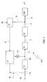
- a front-end 101 of an ammonia plant is fed with a natural gas flow 1 and delivers a make-up syngas 6 to an ammonia synthesis loop 100.
- Said loop 100 is a known technology, and produces an ammonia flow 7.
- the front-end 101 comprises basically a primary steam reformer 10 and a downstream train of equipments for appropriately treating the reformed syngas, in the example a shift and gas-cooling section 11 and a PSA section 12.
- the front-end 101 further comprises an air separation unit or ASU 13.
- Said ASU 13 separates an air input 16 into a nitrogen stream 5 and an O 2 -enriched air stream 8.
- the nitrogen stream 5 is mixed with the purified syngas 4 obtained from the PSA section 12, to adjust the H 2 /N 2 ratio of the stream 6 at the required value for the synthesis of ammonia in the loop 100.
- the front-end 101 further comprises an additional reformer 14, preferably an autothermal reformer or ATR, which operates in parallel with the primary reformer 10.
- additional reformer 14 preferably an autothermal reformer or ATR, which operates in parallel with the primary reformer 10.
- the additional reformer 14 is fed with the enriched air stream 8 delivered by the ASU 13, and with a portion 1 b of the total hydrocarbon feedstock 1, the other portion 1 a of the same feedstock 1 being fed to the primary reformer 10.
- the syngas produced in the additional reformer 14 is optionally cooled in a heat exchanger 17, e.g. a waste heat boiler, and the resulting output flow 9 is joined with the syngas output 2a delivered by the primary reformer 10.
- the stream 2 resulting from the outputs 2a and 9 of the reformers 10 and 14, respectively, is then directed to the shift and gas-cooling section 11.
- the syngas stream 2 basically comprises hydrogen, residual hydrocarbons, steam, CO and CO 2 , plus small amounts of impurities; the CO is converted to CO 2 in the shift section 11 and the gas is then cooled in the same section; the obtained stream 3 is fed to the PSA section 12 where N 2 , CO 2 and the residual hydrocarbons are removed; the purified syngas 4 obtained from said PSA section 12 is added with the nitrogen 5 produced in the ASU unit 13, thus obtaining the make-up syngas 6 containing H 2 and N 2 in a 3:1 molar ratio, suitable for synthesis of ammonia (NH 3 ).
- the pressure of the stream 8 can be raised in a suitable compressor (not shown) between the ASU 13 and the reformer 14.
- the syngas portion 1 b can optionally be mixed with process steam 18 and pre-heated before it enters the additional reformer 14, to improve the overall energy balance.
- the invention is applicable to the revamping of a conventional front-end based on a primary reformer, comprising for example the reformer 10 fed with the available feedstock 1, the units 11 and 12 for purifying the syngas, and the ASU 13 to furnish the required nitrogen, where the enriched air stream 8 is originally vented to atmosphere or fed to the primary reformer 10.
- the existing front-end is revamped at least by adding the additional reformer 14 and modifying the flow lines in order to feed this reformer 14 with a portion 1 b of the total hydrocarbon feedstock, and with the enriched air 8.
- Further means are provided to join the syngas output 9 of said reformer 14 with the syngas output 2a of the primary reformer 10, possibly including the heat-recovery exchanger 17, and/or to pre-heat and mix the steam 18 with the input flow 1 b of the reformer 14.
- Table 1 is a material balance of a prior-art layout as in Fig. 2 , where the front-end is fed with 15368 kg/h (i.e. around 4.27 kg/s) of natural gas, and the output is 25219.9 kg/h of ammonia syngas.
- Table 2 is the balance for the same plant revamped in accordance with Fig. 1 , where total hydrocarbon input is increased to 21370 kg/h of natural gas, and the output is increased to 34414.1 kg/h of ammonia syngas.
- the reforming capability of the plant is augmented by more than 35% without the need to replace or boost the items 210 and 211.
- the Item 212 could require some modifications to make it suitable for the new capacity.
Landscapes
- Chemical & Material Sciences (AREA)
- Chemical Kinetics & Catalysis (AREA)
- Organic Chemistry (AREA)
- Engineering & Computer Science (AREA)
- Combustion & Propulsion (AREA)
- Inorganic Chemistry (AREA)
- Health & Medical Sciences (AREA)
- General Health & Medical Sciences (AREA)
- Hydrogen, Water And Hydrids (AREA)
Claims (14)
- Verfahren zur Herstellung von Frisch-Synthesegas für die Synthese von Ammoniak, umfassend die folgenden Schritte:- Reformieren einer Kohlenwasserstoffbeschickung (1a) in einem Primärreformer (10) ohne einen Sekundärreformer unter Erhalt eines Synthesegasstroms (2) und Behandeln des Synthesegasstroms unter Erhalt eines gereinigten Synthesegases (4), das Wasserstoff enthält;- Trennen einer Luftzuführung (16) in einen Stickstoffstrom (5) und einen mit Sauerstoff angereicherten Luftstrom (8);- Hinzufügen des Stickstoffstroms (5) zu dem gereinigten Synthesegases (4) unter Erhalt eines Frisch-Synthesegases (6), das Wasserstoff und Stickstoff in einem geeigneten molaren Verhältnis für die Synthese von Ammoniak enthält;wobei das Verfahren dadurch gekennzeichnet ist, dass der mit Sauerstoff angereicherte Luftstrom (8) mindestens einem zusätzlichen Reformer (14) zugeführt wird; ein Teil (1b) der gesamten Kohlenwasserstoffeinspeisung (1) wird im zusätzlichen Reformer (14) parallel zu dem Primärreformer (10) unter Erhalt eines zusätzlichen Synthesegasstroms (9) reformiert, wobei der zusätzliche Synthesegasstrom (9) mit dem Synthesegasausgang (2a) des Primärreformers (10) verbunden ist.
- Verfahren nach Anspruch 1, dadurch gekennzeichnet, das der zusätzliche Reformer (14) ein autothermer Reformer ATR ist.
- Verfahren nach Anspruch 1, dadurch gekennzeichnet, dass das Synthesegas (9), das aus dem zusätzlichen Reformer (14) erhalten wird, gekühlt wird, bevor es mit dem Synthesegasaustrag (2a) des Primärreformers (10) verbunden ist.
- Verfahren nach einem der Ansprüche 1 bis 3, dadurch gekennzeichnet, dass der angereicherte Luftstrom (8) von einer Luftzerlegungseinheit (13) geliefert wird und komprimiert wird, bevor dieser dem zusätzlichen Reformer (14) zugeführt wird.
- Verfahren nach einem der vorhergehenden Ansprüche, dadurch gekennzeichnet, dass die Kohlenwasserstoffbeschickung (1b) des zusätzlichen Reformers (14) mit Prozessdampf (18) gemischt und / oder in einem oder mehreren Wärmerückgewinnungswärmetauscher(n) vor dem Eintritt in den zusätzliche Reformer vorgewärmt wird.
- Verfahren nach einem der vorhergehenden Ansprüche, dadurch gekennzeichnet, dass die Behandlung des reformierten Synthesegases in einem Konverter (11) und dann in einem PSA-Abschnitt (12) durchgeführt wird, um jeweils CO in CO2 umzuwandeln und CO2, N2 und restliche Kohlenwasserstoffe zu entfernen.
- Eine Vorrichtung (101) zur Herstellung von Frisch-Synthesegas für die Ammoniaksynthese, umfassend:- einen Primärreformer (10) ohne Sekundärreformer, dem ein Kohlenwasserstoffstrom (1a) zugeführt wird und der einen Synthesegasstrom enthaltend Wasserstoff bereitstellt;- Mittel (11, 12), die angepasst sind, um Verunreinigungen aus dem Synthesegasstrom zu entfernen und um ein gereinigtes Synthesegas (4) zu erhalten;- eine Luftzerlegungseinheit (13), die eine Luftzuführung in einen Stickstoffstrom (5) und einen mit Sauerstoff angereicherten Luftstrom (8) aufteilt;- eine Strömungsleitung zum Mischen des Stickstoffstroms (5) mit dem gereinigten Synthesegases (4) unter Erhalt von Frisch-Synthesegas (6), das Wasserstoff und Stickstoff in einem geeigneten molaren Verhältnis für die Synthese von Ammoniak enthält;wobei die Anlage dadurch gekennzeichnet ist, dass sie mindestens einen zusätzlichen Reformer (14) parallel zu dem Primärreformer (10) umfasst, wobei dem zusätzlichen Reformer ein Kohlenwasserstoffstrom (1b) und der angereicherte Luftstrom (8) zugeführt wird und ein Synthesegasaustrag (9) erzeugt, und wobei sie eine Strömungsverbindung umfasst, die den Synthesegasaustrag (9) des zusätzlichen Reformers und den Synthesegasaustrag (2a) des Primärreformers verbindet.
- Vorrichtung nach Anspruch 7, wobei der zusätzliche Reformer (14) ein autothermer Reformer ist.
- Vorrichtung nach Anspruch 7 oder 8, dadurch gekennzeichnet, dass die Mittel zur Behandlung des reformierten Synthesegases mindestens einen Konverter (11) und dann ein PSA-Gerät (12) zur Entfernung von Kohlendioxid umfassen, wobei der Synthesegasaustrag (9) des zusätzlichen Reformers mit der Synthesegasaustrag (2a) der Primärreformer dem Konverter vorgeschaltet vermischt wird.
- Verfahren zur Modernisierung einer Vorrichtung (101) zur Herstellung von Frisch-Synthesegas für die Synthese von Ammoniak aus der Reformierung einer Kohlenwasserstoffbeschickung (1), wobei die Ausrüstung umfasst:- einen Primärreformer (10) ohne Sekundärreformer, dem ein Kohlenwasserstoffstrom zugeführt wird und der einen Synthesegasstrom enthaltend Wasserstoff bereitstellt;- Mittel (11, 12) zum Entfernen von Verunreinigungen aus dem Synthesegasstrom unter Erhalt von gereinigtem Synthesegas (4);- eine Luftzerlegungseinheit (13), die eine Luftzuführung (16) in einen Stickstoffstrom (5) und einen mit Sauerstoff angereicherten Luftstrom (8) aufteilt;- Mittel zum Mischen des Stickstoffstroms (5) mit dem gereinigten Synthesegases (4), wodurch Frisch-Synthesegas erhalten wird, das Wasserstoff und Stickstoff in einem geeigneten molaren Verhältnis für die Synthese von Ammoniak enthält;wobei das Verfahren zur Modernisierung der Vorrichtung zumindest gekennzeichnet ist durch die folgenden Schritte:- Hinzufügen eines zusätzlichen Reformers (14) parallel zum Primärreformer (10);- Bereitstellen von Mitteln, um den angereicherten Luftstrom (8) aus der Luftzerlegungseinheit (13) dem zusätzlichen Reformer (14) zuzuführen, und Bereitstellen von Mitteln, um einen Teil (1b) der gesamten Kohlenwasserstoffbeschickung (1) dem zusätzlichen Reformer zuzuleiten;- Bereitstellen von Mitteln zur Verbindung des Synthesegasaustrags (9) des zusätzlichen Reformers (14) mit dem Synthesegasaustrag (2a) des Primärreformers (10).
- Verfahren nach Anspruch 10, ferner umfassend die Schritte des Bereitstellens wenigstens eines Kompressors zur Druckerhöhung der angereicherten Luft (8) aus der Luftzerlegungseinheit (13), und von Mitteln, um den komprimierten angereicherten Luftstrom dem zusätzlichen Reformer (14) zuzuführen.
- Verfahren nach Anspruch 10 oder 11, ferner umfassend den Schritt des Bereitstellens zumindest eines Wärmetauschers (17), der zur Kühlung des Synthesegasaustrags des zusätzlichen Reformers (14) geeignet ist.
- Verfahren nach einem der Ansprüche 10 bis 12, ferner umfassend die Schritte des Bereitstellens von Mitteln zum Mischen der Kohlenwasserstoffbeschickung (1b) des zusätzlichen Reformers (14) mit Prozessdampf (18) und / oder zum Vorwärmen der Kohlenwasserstoffbeschickung (1b).
- Verwendung eines O2-angereicherten Luftstroms (8) aus einer Luftzerlegungseinheit (13) des Front-End (101) einer Ammoniaksyntheseanlage ohne Sekundärreformer, zum Einspeisen in einen autothermen Reformer (14), der parallel zu einem Primärreformer (10) des Front-Ends betrieben wird, zur Erzeugung eines zusätzlichen Synthesegasstroms (9), der mit dem Synthesegasstrom (2a) aus dem Primärreformer verbunden ist.
Priority Applications (1)
| Application Number | Priority Date | Filing Date | Title |
|---|---|---|---|
| EP09783903.9A EP2373575B1 (de) | 2008-12-18 | 2009-10-09 | Verfahren und ausrüstung zur herstellung von ammoniak-zusatz-syngas mit einer lufttrennungseinheit als stickstoffquelle |
Applications Claiming Priority (3)
| Application Number | Priority Date | Filing Date | Title |
|---|---|---|---|
| EP20080021962 EP2199253A1 (de) | 2008-12-18 | 2008-12-18 | Verfahren und Ausrüstung zur Herstellung von Ammoniak-Zusatz-Syngas mit einer Lufttrennungseinheit als Stickstoffquelle |
| PCT/EP2009/063193 WO2010069626A1 (en) | 2008-12-18 | 2009-10-09 | Process and equipment for the production of ammonia make-up syngas with an air separation unit as nitrogen source |
| EP09783903.9A EP2373575B1 (de) | 2008-12-18 | 2009-10-09 | Verfahren und ausrüstung zur herstellung von ammoniak-zusatz-syngas mit einer lufttrennungseinheit als stickstoffquelle |
Related Child Applications (1)
| Application Number | Title | Priority Date | Filing Date |
|---|---|---|---|
| EP15172876 Division-Into | 2015-06-19 |
Publications (2)
| Publication Number | Publication Date |
|---|---|
| EP2373575A1 EP2373575A1 (de) | 2011-10-12 |
| EP2373575B1 true EP2373575B1 (de) | 2015-12-16 |
Family
ID=40626976
Family Applications (2)
| Application Number | Title | Priority Date | Filing Date |
|---|---|---|---|
| EP20080021962 Withdrawn EP2199253A1 (de) | 2008-12-18 | 2008-12-18 | Verfahren und Ausrüstung zur Herstellung von Ammoniak-Zusatz-Syngas mit einer Lufttrennungseinheit als Stickstoffquelle |
| EP09783903.9A Not-in-force EP2373575B1 (de) | 2008-12-18 | 2009-10-09 | Verfahren und ausrüstung zur herstellung von ammoniak-zusatz-syngas mit einer lufttrennungseinheit als stickstoffquelle |
Family Applications Before (1)
| Application Number | Title | Priority Date | Filing Date |
|---|---|---|---|
| EP20080021962 Withdrawn EP2199253A1 (de) | 2008-12-18 | 2008-12-18 | Verfahren und Ausrüstung zur Herstellung von Ammoniak-Zusatz-Syngas mit einer Lufttrennungseinheit als Stickstoffquelle |
Country Status (5)
| Country | Link |
|---|---|
| US (1) | US9139431B2 (de) |
| EP (2) | EP2199253A1 (de) |
| AU (1) | AU2009328447B2 (de) |
| RU (1) | RU2011129233A (de) |
| WO (1) | WO2010069626A1 (de) |
Cited By (1)
| Publication number | Priority date | Publication date | Assignee | Title |
|---|---|---|---|---|
| EP3658491B1 (de) | 2017-07-25 | 2023-08-30 | Topsoe A/S | Verfahren zur herstellung von ammoniaksynthesegas |
Families Citing this family (12)
| Publication number | Priority date | Publication date | Assignee | Title |
|---|---|---|---|---|
| US9083020B2 (en) * | 2009-09-04 | 2015-07-14 | Lg Fuel Cell Systems Inc. | Reducing gas generators and methods for generating reducing gas |
| US20110085967A1 (en) * | 2009-10-14 | 2011-04-14 | Troy Michael Raybold | Hydrogen product method and apparatus |
| EP3378832B1 (de) * | 2011-12-19 | 2024-05-08 | Stamicarbon B.V. acting under the name of MT Innovation Center | Verfahren zur verbesserung der herstellung von harnstoff |
| EP2631213A1 (de) * | 2012-02-24 | 2013-08-28 | Ammonia Casale S.A. | Verfahren zur Herstellung von Ammoniaksynthesegas und zugehörige Vorderseite einer Ammoniakanlage |
| CA2875696C (en) | 2012-06-27 | 2020-09-01 | Grannus, Llc | Polygeneration production of power and fertilizer through emissions capture |
| PL2805914T3 (pl) * | 2013-05-23 | 2018-02-28 | Haldor Topsøe A/S | Sposób współwytwarzania amoniaku, mocznika i metanolu |
| US20160251228A1 (en) * | 2015-02-26 | 2016-09-01 | Khalid T. Alkusayer | Ammonia synthesis for fertilizer production |
| US9957161B2 (en) | 2015-12-04 | 2018-05-01 | Grannus, Llc | Polygeneration production of hydrogen for use in various industrial processes |
| CA3010549C (en) | 2016-02-02 | 2023-01-17 | Haldor Topsoe A/S | Atr based ammonia process and plant |
| EP3363770A1 (de) | 2017-02-15 | 2018-08-22 | Casale Sa | Verfahren zur synthese von ammoniak mit geringen emissionen von co2 in die atmosphäre |
| DE102017204208A1 (de) * | 2017-03-14 | 2018-09-20 | Thyssenkrupp Ag | Verfahren und Anlage zur Erzeugung und Aufbereitung eines Synthesegasgemisches |
| CN111526935A (zh) * | 2017-11-09 | 2020-08-11 | 八河流资产有限责任公司 | 用于生产和分离氢气和二氧化碳的系统和方法 |
Family Cites Families (5)
| Publication number | Priority date | Publication date | Assignee | Title |
|---|---|---|---|---|
| DE3047257A1 (de) * | 1980-12-16 | 1982-07-08 | Didier Engineering Gmbh, 4300 Essen | Verfahren zur erzeugung von ammoniak-synthesegas |
| DE3630311A1 (de) * | 1986-09-05 | 1988-03-17 | Linde Ag | Verfahren zur herstellung von ammoniak und kohlendioxid |
| DE4334257A1 (de) * | 1993-10-07 | 1995-04-13 | Linde Ag | Verfahren zum Gewinnen von Ammoniak |
| US5736116A (en) * | 1995-10-25 | 1998-04-07 | The M. W. Kellogg Company | Ammonia production with enriched air reforming and nitrogen injection into the synthesis loop |
| EP0999178B1 (de) * | 1998-11-03 | 2006-07-26 | Ammonia Casale S.A. | Verfahren zur Herstellung von Synthesegas |
-
2008
- 2008-12-18 EP EP20080021962 patent/EP2199253A1/de not_active Withdrawn
-
2009
- 2009-10-09 WO PCT/EP2009/063193 patent/WO2010069626A1/en not_active Ceased
- 2009-10-09 AU AU2009328447A patent/AU2009328447B2/en not_active Ceased
- 2009-10-09 US US13/140,230 patent/US9139431B2/en active Active
- 2009-10-09 EP EP09783903.9A patent/EP2373575B1/de not_active Not-in-force
- 2009-10-09 RU RU2011129233/05A patent/RU2011129233A/ru not_active Application Discontinuation
Cited By (1)
| Publication number | Priority date | Publication date | Assignee | Title |
|---|---|---|---|---|
| EP3658491B1 (de) | 2017-07-25 | 2023-08-30 | Topsoe A/S | Verfahren zur herstellung von ammoniaksynthesegas |
Also Published As
| Publication number | Publication date |
|---|---|
| AU2009328447B2 (en) | 2015-08-13 |
| AU2009328447A1 (en) | 2011-07-21 |
| RU2011129233A (ru) | 2013-01-27 |
| US20110297886A1 (en) | 2011-12-08 |
| WO2010069626A1 (en) | 2010-06-24 |
| US9139431B2 (en) | 2015-09-22 |
| EP2373575A1 (de) | 2011-10-12 |
| EP2199253A1 (de) | 2010-06-23 |
Similar Documents
| Publication | Publication Date | Title |
|---|---|---|
| EP2373575B1 (de) | Verfahren und ausrüstung zur herstellung von ammoniak-zusatz-syngas mit einer lufttrennungseinheit als stickstoffquelle | |
| US11124424B2 (en) | Process for the co-production of methanol and ammonia in parallel | |
| KR100419763B1 (ko) | 농축공기개질및합성루프에로의질소주입에의한암모니아제법 | |
| EP2196448B1 (de) | Verfahren zur gleichzeitigen Herstellung von Methanol und Ammoniak | |
| EP2994415B1 (de) | Verfahren zur herstellung von ammoniaksynthesegas mit hochtemperaturkonvertierung und niedrigem dampf-kohlen-verhältnis | |
| US20120207663A1 (en) | Ammonia Production Process | |
| EP2464601B1 (de) | Verfahren zur Modernisierung eines Ammoniakwerks mit stickstoffbasierter Wäsche eines Spülstroms | |
| KR20130120490A (ko) | 합성 가스의 수소 함량을 향상시키는 방법 | |
| US12215072B2 (en) | Method and system for the synthesis of methanol | |
| EP3224197B1 (de) | Verfahren zur erzeugung von synthesegas durch rauchgasrückführung | |
| US9950928B2 (en) | Process for producing ammonia synthesis gas | |
| WO2019043875A1 (ja) | 高窒素含有天然ガスを用いたアンモニアの製造方法 | |
| EP3390279A1 (de) | Verfahren zur herstellung von ammoniak aus inertfreiem synthesegas in mehreren reaktionssystemen | |
| EA044421B1 (ru) | Способ и установка для получения и обработки смеси синтез-газа |
Legal Events
| Date | Code | Title | Description |
|---|---|---|---|
| PUAI | Public reference made under article 153(3) epc to a published international application that has entered the european phase |
Free format text: ORIGINAL CODE: 0009012 |
|
| 17P | Request for examination filed |
Effective date: 20110707 |
|
| AK | Designated contracting states |
Kind code of ref document: A1 Designated state(s): AT BE BG CH CY CZ DE DK EE ES FI FR GB GR HR HU IE IS IT LI LT LU LV MC MK MT NL NO PL PT RO SE SI SK SM TR |
|
| DAX | Request for extension of the european patent (deleted) | ||
| 17Q | First examination report despatched |
Effective date: 20130108 |
|
| RAP1 | Party data changed (applicant data changed or rights of an application transferred) |
Owner name: CASALE SA |
|
| RIN1 | Information on inventor provided before grant (corrected) |
Inventor name: PANZA, SERGIO |
|
| GRAP | Despatch of communication of intention to grant a patent |
Free format text: ORIGINAL CODE: EPIDOSNIGR1 |
|
| INTG | Intention to grant announced |
Effective date: 20150710 |
|
| GRAS | Grant fee paid |
Free format text: ORIGINAL CODE: EPIDOSNIGR3 |
|
| GRAA | (expected) grant |
Free format text: ORIGINAL CODE: 0009210 |
|
| AK | Designated contracting states |
Kind code of ref document: B1 Designated state(s): AT BE BG CH CY CZ DE DK EE ES FI FR GB GR HR HU IE IS IT LI LT LU LV MC MK MT NL NO PL PT RO SE SI SK SM TR |
|
| REG | Reference to a national code |
Ref country code: GB Ref legal event code: FG4D |
|
| REG | Reference to a national code |
Ref country code: CH Ref legal event code: EP |
|
| REG | Reference to a national code |
Ref country code: IE Ref legal event code: FG4D |
|
| REG | Reference to a national code |
Ref country code: AT Ref legal event code: REF Ref document number: 765463 Country of ref document: AT Kind code of ref document: T Effective date: 20160115 |
|
| REG | Reference to a national code |
Ref country code: DE Ref legal event code: R096 Ref document number: 602009035278 Country of ref document: DE |
|
| REG | Reference to a national code |
Ref country code: NL Ref legal event code: FP |
|
| REG | Reference to a national code |
Ref country code: LT Ref legal event code: MG4D |
|
| PG25 | Lapsed in a contracting state [announced via postgrant information from national office to epo] |
Ref country code: NO Free format text: LAPSE BECAUSE OF FAILURE TO SUBMIT A TRANSLATION OF THE DESCRIPTION OR TO PAY THE FEE WITHIN THE PRESCRIBED TIME-LIMIT Effective date: 20160316 Ref country code: HR Free format text: LAPSE BECAUSE OF FAILURE TO SUBMIT A TRANSLATION OF THE DESCRIPTION OR TO PAY THE FEE WITHIN THE PRESCRIBED TIME-LIMIT Effective date: 20151216 Ref country code: LT Free format text: LAPSE BECAUSE OF FAILURE TO SUBMIT A TRANSLATION OF THE DESCRIPTION OR TO PAY THE FEE WITHIN THE PRESCRIBED TIME-LIMIT Effective date: 20151216 |
|
| REG | Reference to a national code |
Ref country code: AT Ref legal event code: MK05 Ref document number: 765463 Country of ref document: AT Kind code of ref document: T Effective date: 20151216 |
|
| PG25 | Lapsed in a contracting state [announced via postgrant information from national office to epo] |
Ref country code: FI Free format text: LAPSE BECAUSE OF FAILURE TO SUBMIT A TRANSLATION OF THE DESCRIPTION OR TO PAY THE FEE WITHIN THE PRESCRIBED TIME-LIMIT Effective date: 20151216 Ref country code: LV Free format text: LAPSE BECAUSE OF FAILURE TO SUBMIT A TRANSLATION OF THE DESCRIPTION OR TO PAY THE FEE WITHIN THE PRESCRIBED TIME-LIMIT Effective date: 20151216 Ref country code: SE Free format text: LAPSE BECAUSE OF FAILURE TO SUBMIT A TRANSLATION OF THE DESCRIPTION OR TO PAY THE FEE WITHIN THE PRESCRIBED TIME-LIMIT Effective date: 20151216 Ref country code: GR Free format text: LAPSE BECAUSE OF FAILURE TO SUBMIT A TRANSLATION OF THE DESCRIPTION OR TO PAY THE FEE WITHIN THE PRESCRIBED TIME-LIMIT Effective date: 20160317 |
|
| PG25 | Lapsed in a contracting state [announced via postgrant information from national office to epo] |
Ref country code: IT Free format text: LAPSE BECAUSE OF FAILURE TO SUBMIT A TRANSLATION OF THE DESCRIPTION OR TO PAY THE FEE WITHIN THE PRESCRIBED TIME-LIMIT Effective date: 20151216 Ref country code: CZ Free format text: LAPSE BECAUSE OF FAILURE TO SUBMIT A TRANSLATION OF THE DESCRIPTION OR TO PAY THE FEE WITHIN THE PRESCRIBED TIME-LIMIT Effective date: 20151216 Ref country code: ES Free format text: LAPSE BECAUSE OF FAILURE TO SUBMIT A TRANSLATION OF THE DESCRIPTION OR TO PAY THE FEE WITHIN THE PRESCRIBED TIME-LIMIT Effective date: 20151216 |
|
| PG25 | Lapsed in a contracting state [announced via postgrant information from national office to epo] |
Ref country code: SK Free format text: LAPSE BECAUSE OF FAILURE TO SUBMIT A TRANSLATION OF THE DESCRIPTION OR TO PAY THE FEE WITHIN THE PRESCRIBED TIME-LIMIT Effective date: 20151216 Ref country code: AT Free format text: LAPSE BECAUSE OF FAILURE TO SUBMIT A TRANSLATION OF THE DESCRIPTION OR TO PAY THE FEE WITHIN THE PRESCRIBED TIME-LIMIT Effective date: 20151216 Ref country code: IS Free format text: LAPSE BECAUSE OF FAILURE TO SUBMIT A TRANSLATION OF THE DESCRIPTION OR TO PAY THE FEE WITHIN THE PRESCRIBED TIME-LIMIT Effective date: 20160416 Ref country code: PT Free format text: LAPSE BECAUSE OF FAILURE TO SUBMIT A TRANSLATION OF THE DESCRIPTION OR TO PAY THE FEE WITHIN THE PRESCRIBED TIME-LIMIT Effective date: 20160418 Ref country code: RO Free format text: LAPSE BECAUSE OF FAILURE TO SUBMIT A TRANSLATION OF THE DESCRIPTION OR TO PAY THE FEE WITHIN THE PRESCRIBED TIME-LIMIT Effective date: 20151216 Ref country code: EE Free format text: LAPSE BECAUSE OF FAILURE TO SUBMIT A TRANSLATION OF THE DESCRIPTION OR TO PAY THE FEE WITHIN THE PRESCRIBED TIME-LIMIT Effective date: 20151216 Ref country code: SM Free format text: LAPSE BECAUSE OF FAILURE TO SUBMIT A TRANSLATION OF THE DESCRIPTION OR TO PAY THE FEE WITHIN THE PRESCRIBED TIME-LIMIT Effective date: 20151216 |
|
| REG | Reference to a national code |
Ref country code: DE Ref legal event code: R097 Ref document number: 602009035278 Country of ref document: DE |
|
| REG | Reference to a national code |
Ref country code: FR Ref legal event code: PLFP Year of fee payment: 8 |
|
| PLBE | No opposition filed within time limit |
Free format text: ORIGINAL CODE: 0009261 |
|
| STAA | Information on the status of an ep patent application or granted ep patent |
Free format text: STATUS: NO OPPOSITION FILED WITHIN TIME LIMIT |
|
| PG25 | Lapsed in a contracting state [announced via postgrant information from national office to epo] |
Ref country code: DK Free format text: LAPSE BECAUSE OF FAILURE TO SUBMIT A TRANSLATION OF THE DESCRIPTION OR TO PAY THE FEE WITHIN THE PRESCRIBED TIME-LIMIT Effective date: 20151216 Ref country code: PL Free format text: LAPSE BECAUSE OF FAILURE TO SUBMIT A TRANSLATION OF THE DESCRIPTION OR TO PAY THE FEE WITHIN THE PRESCRIBED TIME-LIMIT Effective date: 20151216 |
|
| 26N | No opposition filed |
Effective date: 20160919 |
|
| PG25 | Lapsed in a contracting state [announced via postgrant information from national office to epo] |
Ref country code: BE Free format text: LAPSE BECAUSE OF FAILURE TO SUBMIT A TRANSLATION OF THE DESCRIPTION OR TO PAY THE FEE WITHIN THE PRESCRIBED TIME-LIMIT Effective date: 20151216 |
|
| PG25 | Lapsed in a contracting state [announced via postgrant information from national office to epo] |
Ref country code: SI Free format text: LAPSE BECAUSE OF FAILURE TO SUBMIT A TRANSLATION OF THE DESCRIPTION OR TO PAY THE FEE WITHIN THE PRESCRIBED TIME-LIMIT Effective date: 20151216 |
|
| REG | Reference to a national code |
Ref country code: CH Ref legal event code: PL |
|
| GBPC | Gb: european patent ceased through non-payment of renewal fee |
Effective date: 20161009 |
|
| REG | Reference to a national code |
Ref country code: IE Ref legal event code: MM4A |
|
| PG25 | Lapsed in a contracting state [announced via postgrant information from national office to epo] |
Ref country code: LI Free format text: LAPSE BECAUSE OF NON-PAYMENT OF DUE FEES Effective date: 20161031 Ref country code: CH Free format text: LAPSE BECAUSE OF NON-PAYMENT OF DUE FEES Effective date: 20161031 Ref country code: GB Free format text: LAPSE BECAUSE OF NON-PAYMENT OF DUE FEES Effective date: 20161009 |
|
| PG25 | Lapsed in a contracting state [announced via postgrant information from national office to epo] |
Ref country code: LU Free format text: LAPSE BECAUSE OF NON-PAYMENT OF DUE FEES Effective date: 20161009 |
|
| REG | Reference to a national code |
Ref country code: FR Ref legal event code: PLFP Year of fee payment: 9 |
|
| PG25 | Lapsed in a contracting state [announced via postgrant information from national office to epo] |
Ref country code: IE Free format text: LAPSE BECAUSE OF NON-PAYMENT OF DUE FEES Effective date: 20161009 |
|
| PG25 | Lapsed in a contracting state [announced via postgrant information from national office to epo] |
Ref country code: HU Free format text: LAPSE BECAUSE OF FAILURE TO SUBMIT A TRANSLATION OF THE DESCRIPTION OR TO PAY THE FEE WITHIN THE PRESCRIBED TIME-LIMIT; INVALID AB INITIO Effective date: 20091009 Ref country code: CY Free format text: LAPSE BECAUSE OF FAILURE TO SUBMIT A TRANSLATION OF THE DESCRIPTION OR TO PAY THE FEE WITHIN THE PRESCRIBED TIME-LIMIT Effective date: 20151216 |
|
| PG25 | Lapsed in a contracting state [announced via postgrant information from national office to epo] |
Ref country code: MC Free format text: LAPSE BECAUSE OF FAILURE TO SUBMIT A TRANSLATION OF THE DESCRIPTION OR TO PAY THE FEE WITHIN THE PRESCRIBED TIME-LIMIT Effective date: 20151216 Ref country code: MT Free format text: LAPSE BECAUSE OF NON-PAYMENT OF DUE FEES Effective date: 20161031 Ref country code: MK Free format text: LAPSE BECAUSE OF FAILURE TO SUBMIT A TRANSLATION OF THE DESCRIPTION OR TO PAY THE FEE WITHIN THE PRESCRIBED TIME-LIMIT Effective date: 20151216 Ref country code: TR Free format text: LAPSE BECAUSE OF FAILURE TO SUBMIT A TRANSLATION OF THE DESCRIPTION OR TO PAY THE FEE WITHIN THE PRESCRIBED TIME-LIMIT Effective date: 20151216 |
|
| PG25 | Lapsed in a contracting state [announced via postgrant information from national office to epo] |
Ref country code: BG Free format text: LAPSE BECAUSE OF FAILURE TO SUBMIT A TRANSLATION OF THE DESCRIPTION OR TO PAY THE FEE WITHIN THE PRESCRIBED TIME-LIMIT Effective date: 20151216 |
|
| REG | Reference to a national code |
Ref country code: FR Ref legal event code: PLFP Year of fee payment: 10 |
|
| P01 | Opt-out of the competence of the unified patent court (upc) registered |
Effective date: 20230527 |
|
| PGFP | Annual fee paid to national office [announced via postgrant information from national office to epo] |
Ref country code: NL Payment date: 20230922 Year of fee payment: 15 |
|
| PGFP | Annual fee paid to national office [announced via postgrant information from national office to epo] |
Ref country code: FR Payment date: 20230920 Year of fee payment: 15 |
|
| PGFP | Annual fee paid to national office [announced via postgrant information from national office to epo] |
Ref country code: DE Payment date: 20230920 Year of fee payment: 15 |
|
| REG | Reference to a national code |
Ref country code: DE Ref legal event code: R119 Ref document number: 602009035278 Country of ref document: DE |
|
| REG | Reference to a national code |
Ref country code: NL Ref legal event code: MM Effective date: 20241101 |
|
| PG25 | Lapsed in a contracting state [announced via postgrant information from national office to epo] |
Ref country code: DE Free format text: LAPSE BECAUSE OF NON-PAYMENT OF DUE FEES Effective date: 20250501 |
|
| PG25 | Lapsed in a contracting state [announced via postgrant information from national office to epo] |
Ref country code: NL Free format text: LAPSE BECAUSE OF NON-PAYMENT OF DUE FEES Effective date: 20241101 |
|
| PG25 | Lapsed in a contracting state [announced via postgrant information from national office to epo] |
Ref country code: FR Free format text: LAPSE BECAUSE OF NON-PAYMENT OF DUE FEES Effective date: 20241031 |