EP2373878B1 - A microsatellite comprising a propulsion module and an imaging device - Google Patents
A microsatellite comprising a propulsion module and an imaging device Download PDFInfo
- Publication number
- EP2373878B1 EP2373878B1 EP08878787.4A EP08878787A EP2373878B1 EP 2373878 B1 EP2373878 B1 EP 2373878B1 EP 08878787 A EP08878787 A EP 08878787A EP 2373878 B1 EP2373878 B1 EP 2373878B1
- Authority
- EP
- European Patent Office
- Prior art keywords
- chamber
- thrust
- spacecraft according
- fuel
- valve
- Prior art date
- Legal status (The legal status is an assumption and is not a legal conclusion. Google has not performed a legal analysis and makes no representation as to the accuracy of the status listed.)
- Not-in-force
Links
Images


Classifications
-
- B—PERFORMING OPERATIONS; TRANSPORTING
- B64—AIRCRAFT; AVIATION; COSMONAUTICS
- B64G—COSMONAUTICS; VEHICLES OR EQUIPMENT THEREFOR
- B64G1/00—Cosmonautic vehicles
- B64G1/10—Artificial satellites; Systems of such satellites; Interplanetary vehicles
- B64G1/1021—Earth observation satellites
-
- B—PERFORMING OPERATIONS; TRANSPORTING
- B64—AIRCRAFT; AVIATION; COSMONAUTICS
- B64G—COSMONAUTICS; VEHICLES OR EQUIPMENT THEREFOR
- B64G1/00—Cosmonautic vehicles
- B64G1/22—Parts of, or equipment specially adapted for fitting in or to, cosmonautic vehicles
- B64G1/24—Guiding or controlling apparatus, e.g. for attitude control
- B64G1/26—Guiding or controlling apparatus, e.g. for attitude control using jets
-
- B—PERFORMING OPERATIONS; TRANSPORTING
- B64—AIRCRAFT; AVIATION; COSMONAUTICS
- B64G—COSMONAUTICS; VEHICLES OR EQUIPMENT THEREFOR
- B64G1/00—Cosmonautic vehicles
- B64G1/22—Parts of, or equipment specially adapted for fitting in or to, cosmonautic vehicles
- B64G1/40—Arrangements or adaptations of propulsion systems
- B64G1/402—Propellant tanks; Feeding propellants
-
- B—PERFORMING OPERATIONS; TRANSPORTING
- B64—AIRCRAFT; AVIATION; COSMONAUTICS
- B64G—COSMONAUTICS; VEHICLES OR EQUIPMENT THEREFOR
- B64G1/00—Cosmonautic vehicles
- B64G1/22—Parts of, or equipment specially adapted for fitting in or to, cosmonautic vehicles
- B64G1/66—Arrangements or adaptations of apparatus or instruments, not otherwise provided for
-
- F—MECHANICAL ENGINEERING; LIGHTING; HEATING; WEAPONS; BLASTING
- F02—COMBUSTION ENGINES; HOT-GAS OR COMBUSTION-PRODUCT ENGINE PLANTS
- F02K—JET-PROPULSION PLANTS
- F02K9/00—Rocket-engine plants, i.e. plants carrying both fuel and oxidant therefor; Control thereof
- F02K9/42—Rocket-engine plants, i.e. plants carrying both fuel and oxidant therefor; Control thereof using liquid or gaseous propellants
- F02K9/60—Constructional parts; Details not otherwise provided for
- F02K9/605—Reservoirs
-
- F—MECHANICAL ENGINEERING; LIGHTING; HEATING; WEAPONS; BLASTING
- F02—COMBUSTION ENGINES; HOT-GAS OR COMBUSTION-PRODUCT ENGINE PLANTS
- F02K—JET-PROPULSION PLANTS
- F02K99/00—Subject matter not provided for in other groups of this subclass
-
- B—PERFORMING OPERATIONS; TRANSPORTING
- B64—AIRCRAFT; AVIATION; COSMONAUTICS
- B64G—COSMONAUTICS; VEHICLES OR EQUIPMENT THEREFOR
- B64G1/00—Cosmonautic vehicles
- B64G1/10—Artificial satellites; Systems of such satellites; Interplanetary vehicles
- B64G1/1021—Earth observation satellites
- B64G1/1028—Earth observation satellites using optical means for mapping, surveying or detection, e.g. of intelligence
Definitions
- the invention relates to systems, modules and methods for the use of vehicles, such as those used for orbiting microsatellites, and the ancillary devices used therewith.
- Imaging from Space to Earth or other Space targets rely on the use of spacecraft equipped with cameras or telescopes using refractive or reflective lenses and sensor, detectors and attitude control devices such as thrusters, reaction wheels, gyroscopes to point such optical systems in the desired direction. Using more than one of such spacecrafts imaging the same target it may be possible to achieve a resolution higher than the one of each single optic. However, this requires precise knowledge and control of the relative position of the spacecraft.
- Reaction wheels, gyroscopes and other "internal systems" are ineffective to control relative positions of spacecraft; the only useful systems are based on the action-reaction principle thereby requiring ejection of mass from the spacecraft to generate the needed thrust. Therefore all such thrusters require a container for the material to be expelled which is usually stored in a fluid form such as gas or liquid. Independently on the containment method and propulsion principle, the size of the container ultimately limits the maneuvering lifetime and therefore the usability of the imaging spacecrafts. A bigger container will allow for a longer lifetime for identical other parameters.
- High resolution optics in whichever part of electromagnetic spectrum, requires big focal lengths for high magnifications and large apertures to collect sufficient amount of radiation from the far away targets to impress the detection sensors.
- propellant containers and optical systems are competing for volume available on the spacecraft when designing them for the best performances. Having such systems separately arranged on a spacecraft requires strong structures for both of them; in fact the propellant container has to withstand pressures and accelerations loads, while the optics needs high structural stiffness to guarantee precise positioning of the lenses. Such separate strong structures increase the total mass of the spacecraft and ultimately their manufacturing and launch costs.
- United States Patent No. 6,131,858 discloses a compact single-propellant unitary propulsion system for placing a satellite into an orbit and subsequently correcting the orbit so that the satellite is stabilized on three axes.
- the system comprises a liquid propellant tank secured to a satellite platform and having a reinforced bottom wall with an outlet and filter element, a distribution block welded to the reinforced bottom wall, at least one filling/emptying value mounted on the distribution block, and a set of at least two thrusters mounted on the distribution block and fed directly from the distribution block without additional pipework.
- the set of at least two thrusters point substantially along the axis of the tank, which is aligned with the axis of the satellite.
- the propulsion system may be fully assembled before it is integrated with the satellite.
- United State Patent No. 3,532,297 discloses an attitude control system for space vehicles using a subliming solid as the propellant. The system employs a quartz lens to cause sublimation of the propellant.
- a microsatellite comprises a propulsion module for moving and/or pointing said micro satellite; an imaging device mounted to said propulsion module; a fuel supply; wherein said fuel supply is located within said imaging device.
- an electromagnetic valve comprises a substrate having an inlet port; a planar valve assembly said valve assembly comprising a valve frame and a selectively movable seat member co-planar with said static member; said planar valve assembly forming a layer on the valve frame; an electro magnetic coil having an axis perpendicular to a plane of said valve assembly; said electromagnetic coil being adjacent to said valve assembly; said seat member having a ferromagnetic material placed on a portion adjacent to said electromagnetic coil; wherein on energizing the electromagnetic coil the seat member is arranged to move within the plane of the valve frame towards said coil from a closed position sealing the inlet port to an open position opening the inlet port.
- an electromagnetic valve for selectively switching fluid communication between an inlet port and either a first and second outlet port
- the valve comprises a substrate having the inlet port; a planar valve assembly said valve assembly comprising a valve frame and a selectively movable seat member co-planar with said static member; said planar valve assembly forming a layer on the valve frame; an electro magnetic coil having an axis perpendicular to a plane of said valve assembly; said electromagnetic coil being adjacent to said valve assembly; said seat member having a ferromagnetic material placed on a portion adjacent to said electromagnetic coil; wherein on energizing the electromagnetic coil the seat member is arranged to move within the plane of the valve frame towards said coil from a first position opening the first outlet port and sealing the second outlet port to second position opening the second outlet port and sealing the first outlet port.
- an isolation valve for sealing a fluidic channel comprises a membrane located across the channel said member capable of withstanding pressure within said fluidic channel; a heating source congruent with said membrane; the heating source arranged to disrupt the membrane and so permit fluid flow across the membrane through the fluidic channel; wherein said heating source includes a resistor connected to a power supply said resistor having a heating surface congruent with said membrane.
- a multiple actuation valve comprises a block having an inlet and an outlet; a deformable membrane congruent with said inlet and outlet; a biasing member arranged to selectively bias the membrane into sealing contact with the inlet and outlet, wherein on removal of the bias applied by the biasing member, the deformable membrane is arranged to by deform to permit fluid communication between the inlet and outlet.
- a latch assembly comprises a housing; a socket within said housing, said socket and housing in rotational engagement about a central axis; a pin in sliding engagement with said housing from a retracted position to an extended position along said central axis; wherein in the retracted position, a first portion of the pin is shaped to prevent relative rotation of the housing and socket, and in the extended position a second portion is shaped to allow rotation of the housing and socket.
- a support apparatus comprises a first and second magnet having axial magnetization and facing opposite polarity and positioned so as to generate a selectively adjustable repulsing force; the first magnet fixed to a bracket; the second magnet positioned above the first magnet in rotational engagement; wherein the second magnet is arranged to be mounted to a rotating device with the repulsive force adjusted to support the weight of the device and permit free rotation of said device through relative rotation of the first and second magnets.
- optical and propellant containment systems may be combined in order to share efficiently volumes and structures.
- the propellant material is sufficiently transparent to the electromagnetic waves that need to be collected by the detector sensor, the propellant material refraction properties are negligible or can be taken in to account in the design of the optical system and the structure can withstand the pressure of the propellant with negligible or controllable deformation.
- the techniques disclosed herein are applicable for a vehicle moving through space, such as a microsatellite traveling in an orbital path.
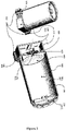
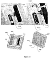
- the microsatellite according to the embodiment of Figures 1 and 2 includes an optical chamber, or tube 100 closed at one side by an optically transparent window 110 and at the other side by a flange 120 that allows for the placement of an optical detector 130 in correspondence with an opening 125.
- the window 110 can also be conveniently shaped as a lens to perform a focusing or correction function in combination with the other lenses or mirrors that combine the optical system.
- the window 110 has at least the function of closing the tube 100 also with the help of a gasket 115 so that the optical tube 100 can contain a pressurized fluid 200 to be used as propellant.
- the opening 125 allows for an optical detector 130 such as a CCD or CMOS to receive the image projected by the optical system of lenses and mirrors on the focal plane.
- the sensor 130 can be before or behind a cover 140 that close hermetically the optical tube 100 also thanks to a gasket 145.
- a set of focusing and correcting lenses or mirrors 150 can be placed inside the tube by means of spacers 155 in a way commonly used in telescope optics with the only care of allowing for pressure equalization holes 157 among the various sub-chambers created between the lenses.
- the elements 100, 110, 115, 120, 140 and 145 define a closed volume, such as a fuel supply or more specifically a fuel chamber 210 that contains the propellant fluid/fuel 200 preferably in the form of pressurized gas, but also possibly as liquid.
- the sensor 130 If the sensor 130 is inside the volume 210 then its electrical and electronic connection cables will pass through the containing walls by means of a dedicated feed-through connector 220.
- the Figure 2 represents an optical configuration known as Matsukov-Cassegrain which typically guarantees a very compact volume with a considerably long focal length.
- the light from the imaged target first passes through the window 110 which has also the function of correcting lens to reduce the typical aberration of such kind of reflective optic. Then the light rays pass in the optical tube through the stored propellant gas and are reflected by the main mirror 160 placed at the end of the tube 100 on the flange 120. After reflection they hit the secondary mirror 170 placed at the entrance of the tube 100 and are reflected back again until they reach the sensor 130 through the opening 125 in the main mirror and 126 in the flange 120.
- the optics are attached to various points of the tube 100, care should be taken in the design to ensure negligible deformations of the tube under pressure so that the optical geometry is not disturbed.
- the optics can be suspended to a structure 250 internal to the tube and subjected to balanced pressures.
- the optics can use deformable supporting structures composed by sealed chambers that deform in a shape canceling the optical effects on the fluid.
- the propellant is stored in liquid form it is essential to avoid any liquid free surface or sloshing.
- This can be achieved by a bellow 260 inserted in the optical tube 100 and terminated by a flat transparent window 261 that contains the liquid 200 and contracts as it is used in order to keep it under pressure.
- the transparent window 261 will be part of a piston 262 sliding inside the optical tube 100 and keeping pressurized the fluid by means of a spring 263 or pressurized gas inserted in the chamber 211 defined by the windows 261 and 110.
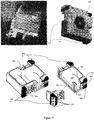
- FIG. 1 shows the propulsion module 300 attached to the optical tube and propellant main container 100.
- the propulsion module is also performing the function of secondary propellant container, whereby its internal volume 310 is connected to the optical tube volume 210 through the windows 125 and 126.
- the optical sensor 130 and its electronics 135 as well as other satellite electronics 136 can be contained inside the volume 310 where they are also very well protected from space radiations by the metallic walls constituting the module 300.
- Placement for thruster modules 320 that control the attitude of a spacecraft is at the opposite corners of the spacecraft external envelope. It is also known that 2 couples of modules each with 4 nozzles 330 in cross and opposite configuration can control the attitude of the spacecraft on the 3 axes by subsequent rotations about two axis thanks to the torques achieved by firing opposite thrusters on opposite modules.
- This invention allows the integration of such opposite thruster modules 320 at opposite corners a & b of the propulsion module 300 without using any connecting pipe that is typically a risk of leakages and also of difficult assembly.
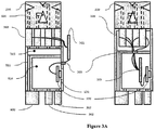
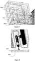
- the pipeless integration is obtained by screwing the thrust control valves 360 directly between the wall of the propulsion module and the thruster module. Since the valves 360 may still present a minimal leakage an isolation valve 400 is introduced to separate the actual gas volume 310 from the valve inlet volume 315. For easy assembly and replacement the isolation valve 400 is attached to one of the corners of the micropropulsion module 300 left available by the thruster modules.
- a drilled channel 309 connects the inlet of the valve 400 to the volume 310, while another drilled channel 311 connects the outlet of the valve 400 to the plenum 315 drilled in the walls of the module 300 also connected to the thrust control valves 360.
- the transversal channel 312 necessary to connect the isolation valve 400 with the thruster module 320 b at the opposite corner is drilled in an internal rib of the module 300 that acts as structural stiffening element. Nearby the isolation valve is placed the gas filling check valve 362 and the pressure sensor 363 also connected to the volume 310 by means of drilled holes.
- the electronic cables pass through the module wall 300 by means of feed trough connectors 305.
- a pressure regulator 380 may be necessary to supply the various valves at lower pressure.
- the pressure regulator can be on the inlet of the isolation valve, at its outlet or between the main tank 100 and the secondary tank 300, especially if the electronics 135 and 136 do not tolerate high pressures.
- an extendible structure may bring the first group of lenses forward once the satellite is deployed and ready to operate.
- This structure can be made by 2 or more sliding rods activated by compression springs or other extension actuators and released and locked in place by pyrotechnic latches 500.
- the whole optical tube can be divided in cylindrical sliding sections 101 extending to the full length under the pressure of the propellant once the latches are released thereby reducing the pressure in the tank to produce less stress on joints and gaskets and less risk of leakages. Accordingly, this may act as stress relaxation on the structure to minimize or eliminate fatigue, creep or other detrimental time dependent effects.
- the embodiment allows for the existence of a double hierarchy of chambers, the main chamber 210 containing the fuel and connected to the telescope volume, the second chamber connected to the thruster modules 320 by means of the thrust ports on the housing walls, the two chambers connected together by means of peripheral equipment (i.e. an isolation valve) that allows said connection only when thrust is required, otherwise isolating the main chamber from the second chamber to minimize or cancel the risk of leakages.
- peripheral equipment i.e. an isolation valve
- valves 360 can be conveniently placed inside the second chamber 315, as shown in Figure 3B , thereby avoiding at least one fluidic joint and the related risk of leakages or reduced reliability.
- the lid 302 can be simply flat and even soldered on the box 300 if no electronic needs to be inserted.
- the thruster module 320 are mainly composed by a body 321, a set of micro valves 360, a microvalve gasket retainer 361 that compresses the sealing gaskets 362, a set of micronozzles 330, a micronozzle retainer 326 that lock them against the body 321 and compresses the sealing gaskets 326, all assembled by screws.
- Simplified versions may be made employing 3, 2 or even just one nozzle and valve.
- Alternative embodiments include the use heating or vaporization of the propellant by introducing a resistor 381 in the duct 380 before the nozzle 330 as shown in Figure 5 .
- Nozzle and duct are sealed by gaskets 382 and 384, the resistor is connected to an external electric circuit by means of conducting wires 383 passing through the duct 380 which is made of high temperature insulating material such as machinable ceramic "MacorTM".
- the wires 383 are sealed by means of glass frit or similar means. The whole group is kept assembled by the head 386 and screws 387.
- microvalves Although commercially available microvalves are perfectly compatible with the described configuration, we present a novel microvalve which achieves size and mass reduction by possible full integration in the micronozzle without sacrifice simplicity of manufacturing and assembly.
- Microvalves can be classified first in terms of manufacturing technology, which defines the general architecture, as MEMS or Precision Engineering microvalves.
- MEMS microvalves as any other MEMS device, are realized on a typical flat substrate (Wafer), which could be a combination of silicon, glass or plastic, in order to use photolithographic and etching batch processes.
- Precision engineering microvalves have a more three-dimensional structure enabled by individual machining, punching or molding of each component.
- MEMS microvalves are composed by a cavity realized in one of the substrates and closed by the other substrate which presents one hole that is the valve orifice.
- valve orifice is then closed or opened by an actuator, often realized in the form of a membrane, moving perpendicularly to the flat substrates and actuated in different ways, typically by means of:
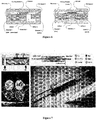
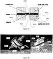
- Figure 7 represents a thermally actuated MEMS microvalve from the company Redwood Microsystems and an electromagnetically actuated precision engineering microvalve from the company Lee.
- typical MEMS microvalves don't use the electromagnetic actuation which is normally used in Precision Engineered microvalve.
- electromagnetic actuation requires including a relatively large ferromagnetic element in the moving part of the actuator and this is not easily achievable with MEMS batch processes.
- the performances obtainable with the use of electromagnetic effect are higher for the same actuator volume and energy used in terms of resulting speed and force on the actuator. This is due to the intrinsically higher energy density achievable with a well designed electromagnetic actuator.
- Another reason that normally discourages MEMS system to use the electromagnetic actuation is the complication in the realization of necessary coils and magnetic circuits due to material incompatibility, difficulty to be arranged in the typical flat architecture of MEMS and difficulty to realize the three-dimensional winding of the coil.
- the capability to obtain high actuation forces is fundamental for a good valve. Additionally, the opening speed is very important to perform precise control of the amount of fluid allowed to flow. This can be achieved if the actuation force is high and it can be applied instantaneously.
- the function of the moving part does not relate to any fluidic channel or orifice, therefore the movement can be directed along the flat surface of the MEMS substrates and the electrostatic principle of actuation has been generally used; typical structures in this case are commonly called “interdigitated” due to the fingerlike shape as clearly shown in Figure 8 .
- the valve actuator is a miniaturized electromagnetic coil which axis is placed perpendicular to the substrate in which the microvalve mechanism is realized.
- This solution not yet applied by any MEMS valve allows using relatively big magnetic circuit to actuate the microvalve mechanism.
- the moving part of the valve contains a little element of ferromagnetic material which interacts with the electromagnetic coil for the actuation.
- the axis of the electromagnetic coil is mounted out of the center of the ferromagnetic element at its resting position when the valve is closed. The actuation is achieved when the coil is energized and the magnetic field pulls the ferromagnetic element towards the centre of the coil to minimize the energy of the electromagnetic field.
- the return and keeping in the closed position is realized by a spring embedded in the structure of the valve.
- the spring is preloaded during assembling of the valve by the insertion of the sealing element which is slightly thicker than the room provided for it at zero loading of the spring. Such preload guarantees the compression of the sealing element and therefore the absence of fluid leakages through the valve.
- the extension of the actuator to the open position of the valve is limited by a stopper realized in the geometry of the actuator moving part; such limit guarantees that the stresses in the spring element are kept under the levels compatible with the elastic behavior of the material and well below the yield margin of the material.
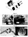
- the fluidic valve is mainly composed of the same basic elements as any other valve such as described earlier, which are here arranged in a planar fashion along the substrate material in this particular embodiment 5000: inlet channel 5009, orifice 5010, sealing gasket 5005, gasket seat 5003 outlet channel 5011, closing element 5003, spring 5004 and actuator 5020.
- the electromagnetic actuating solenoid 5020 with its coil 5021 can be arranged independently from the substrates in any position suitable for the magnetic field to interact with the moving element. A possible configuration is shown in Figure 9 .
- microfluidic planar part of such configuration can be realized by means of Etching technology on silicon and it requires 2 internal silicon layers 5102, 5103 and 2 external glass layers 5101, 5104 in its most efficient embodiment as shown in Figure 10-4 layers valve construction: a) view; b) cut view Figure 10, Figure 11 and Figure 13 .
- the four layers construction 5100 has the spring 5004 and moving body 5002 split in two symmetric parts (i.e. 5004a and 5004b) with the orifice 5010 realized in between them. This symmetry is necessary to allow a perfectly symmetrically aligned loading of the spring 5004 pressing the gasket 5005 on its seat 5002.
- the opening of the valve is achieved with the translation of the moving body 5103 by the action of the electromagnetic field provided by the electromagnet 5120 when its coil 5121 is energized and attracts the anchor 5122.
- the moving body 5103 releases its pressure on the seal 5105 and the fluid is allowed to flow from the inlet channel 5109 through the opened orifice in the outlet channel 5111 that can be made exiting perpendicularly to the substrates or parallel to them in a micronozzle 5090.
- the sealing 5105 is inserted in a slot between the moving body and the orifice seat.
- Such slot is realized by manufacturing at a slightly smaller size than that of the gasket in order to compress the inserted gasket by means of the extension required to the spring 5104 when the gasket is in place.
- This special feature may allow the complete valve body, spring, moving body, orifice and gasket seat to be formed as only one monolithic part.
- a simplest embodiment 5200 is possible using only two wafers (named "2L" microvalve) for fabrication in facilities with less experience.
- 2L two wafers
- only half of the sandwich will be realized using only one silicon wafer 5201 and one glass wafer 5202 and the structure will not be symmetric about its mid plane and it will be completed by inserted the chip in a packaging 5203 providing the bottom of the inlet 5209 and outlet 5210, 5211 fluidic connections.
- the fluidic passages are then completed by pressing the two-wafer sandwich chip in a packaging with a profiled seal 5212.
- a packaging with a profiled seal 5212.
- Such package can be made in any material provided it is diamagnetic and it allows to keep the magnetic circuit with minimum gaps.
- this embodiment has been configured to have one inlet 5209 and two outlet channels 5211a and 5211b as well as two gaskets 5205a and 5205b so that the valve can have one channel open for return of fluid at any time while the other is closed.
- the two silicon wafers 5102 and 5103 are lithographed and etched on both faces to create the channels, and to create the gap that will allow the moving part to translate and they are etched through to create the elastic spring and allow the movement of the moving part.
- the gasket realized in a soft metal able to withstand the bonding temperature must be inserted in place.
- the bottom glass 5104 is purchased already with holes 5104a in place.
- the anchor made of ferromagnetic material is put in place.
- the chips are diced from the wafer.
- a pressure sensor can be easily integrated in the system by taking advantage of the deformation of the chamber of the valve under pressure.
- an electrodeposited and lithography patterned layer of resistors 5301a to 5301d and conductors will realize a Wheatstone bridge which electric unbalance produced by the chamber deformation can be detected by an external circuit and correlated to the internal pressure.
- the electrical connection will be realized by probes or wire bonding or by soldering to the electrode pads 5302a to 5302d.
- the outlet of the valve can be connected on the hole realized on the bottom 5111 or on the side of the chip 5090 through a convergent divergent micronozzle, thereby realizing a fully integrated MEMS controllable microthruster or micro-mass flow controller as shown in Figure 18 .
- the isolation valve 400 is made in two different configurations: single actuation and multiple actuation.
- the single actuation valve is based on a membrane melted by a small resistor reaching high temperature by Joule effect.
- the thermally actuated isolation valve is composed by a thin membrane 4005 supported on a robust diaphragm 4003 with holes 4006 which separate the tank volume from the piping connection.
- the membrane is weakened and eventually locally melted by a heater 4004 in order to allow the pressure of the gas in the tank to brake the membrane and open the valve.
- the supporting diaphragm is placed between the tank body 4001 and the piping collector body 4002.
- the heater 4004 is a commercial Surface Mounted Device resistor of 500hm or two or more of them placed on the sides around the hole 4006 for a total resistance of 100Ohm in a combination of parallel and series (two resistors of 100Ohm in parallel or two parallel couples of 25Ohm resistors in series). A voltage of 12V is applied to the resistors 4004.
- T the fluid passes through the valve in one direction
- R the fluid passes through the valve and returns on the same side where it entered after the opening of the valve
- the membrane 4105 is supported by a printed circuit board, "PCB" 4103 also supporting one or more resistors 4104 to which it provides electrical connections.
- the membrane 4105 and the PCB 4103 are sandwiched between the body 4101 connected to the pressurized tank and the body 4102 connected to the downstream piping.
- the resistors 4104 are placed besides one or more holes 4106. The complete sandwich is leak free thanks to two gaskets 4107 and packed by means of screws 4108.
- valve "R” The basic embodiment of the valve "R” is made by a main body 4201 and a closing head 4202 sandwiching the membrane 4205 and its support 4203 carrying the resistors 4204 and presenting holes 4206 for the passage of the gas through the valve.
- valve "T” The difference with the valve "T” is evident by observing the function of the head 4201 to redirecting the flow to the main body 4201 through a second hole in the membrane support 4203.
- the isolation valve "R” is of easier replacement operating only from one side of the tank and not between tank and piping as in the case of the valve "T".
- isolation valve “R” There are two variations in the embodiments for the isolation valve "R", one in which the body of the valve is made by two bulky bodies 4201 and 4202 , named “RB”, and one in which the valve is a sandwich of thin substrates (named “RS").
- the main difference consists in the sealing used between the membrane and the downstream body. Such body is in contact with the backside of the PCB supporting the sealing membrane.
- the sealing is achieved by means of micro O-Rings 4207 compressed between the bodies and micropipes 4209 that runs between the bodies thereby creating alignment to the tank and solidity of the system.
- the membrane is glued on the heater substrate by means of an additional sticky tape layer 4204a or being itself realized by punching from a sticky tape.
- the choice of the membrane material must be such as to be able to withstand normal high temperature up to 150 C and low temperature down to -50C, and at the same time it must be able to reach melting point at around 250C before the heat produced by the heater reaches other vital elements such as the O-Rings 4207 or more peripheral areas of the membrane thereby.
- a typical opening time of 500 ms is obtained and a complete opening is stabilized by keeping the heating as long as 1s or 2s.
- the opening of the valve can be observed by monitoring the downstream pressure rising as shown in Figure 25 .
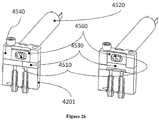
- Figure 26 shows a multiple actuation valve 450, here represented as a modification of the previous single actuation "R" isolation valve, is based on a rotating cam 4510 moved by an electric motor which 4520 closes and opens a deformable membrane 4530 placed between body 4201 and head 4540 of the valve.
- the motor using a reduction gearbox if necessary, moves a biasing member, in this case a sliding element 4560, by means of the eccentric cam 4510 mounted on its shaft.
- the sliding element pushes the deformable membrane 4530, possibly made in rubber, which is pressed against the inlet and outlet holes as well as against the flat region between the holes thanks to a tight tolerance assembly.
- the pyrotechnic latch 500 can be "protruding pin” or “rotation locked” and is based on a small explosive charge 510 such as a mixture of Potassium Perchlorate and Aluminum powders ignited by a small resistor 520 and displacing a small piston 530 which moves a protruding tip or disengage a rotating element 540.
- a small explosive charge 510 such as a mixture of Potassium Perchlorate and Aluminum powders ignited by a small resistor 520 and displacing a small piston 530 which moves a protruding tip or disengage a rotating element 540.
- the protruding pin latch is a simplified version of the rotation locked which will be described here.
- the latch is mainly composed by a body 550 and a shaft 530, the shaft has a chamber 535 at its inner end and a small Printed Circuit Board (PCB) 560 is inserted from a slot in the body 550 to complete such chamber volume.
- PCB Printed Circuit Board
- Such PCB has at least one small resistor 560 facing the chamber volume and connected externally to an electric circuit by means of isolated leads along the PCB.
- the other end of the shaft has a square section 536 which engages with a retainer element 570 screwed on the body and with the hub 580 attached to the body by means of a bearing 585 or equivalent rotating joint.
- Retainer and Hub have a rectangular slot 590 that does not allow the relative rotation of shaft, retainer and hub.
- the chamber is filled with explosive material 510 which is ignited if current passing in the electric circuit heats up the resistor and the adjacent explosive material to the ignition temperature.
- the resulting explosion pushes the shaft 530 forward as shown in Figure 27b and disengages its square end 536 from the retainer and hub presenting a circular portion 537 to their rectangular slot.
- the conical mating 538 between shaft and retainer is locked thanks to its small angle.
- the hub is now free to rotate and the shaft is locked in open position.
- the thrust measurements have been realized by means of a new microbalance, based on the concept of torsion balance and modified by using a hollow pipe 2305 to supply the pressurized propulsion fluid from an external tank 2304 and to provide the elastic element sensing the thrust force whose deformation is measured at the tip of the arm 2306 where the thrust is produced by the thruster 201.
- the elastic torsion suspension removes the presence of any friction therefore allowing, in combination with an optocoupling circuit or radio to actuate the thruster valve 2307, the measure of the exact force produced by the microthruster.
- very thin conductors attached to a flange 2309 can be added to the system and the small additional stiffness introduced can be numerically deducted by the measurement of the oscillation period with and without such wires.
- the valve can be placed upstream the elastic pipe loosing the capability to create very small thrust pulses but allowing for perfect elastic suspension.
- the realization of the balance requires a perfect equilibrium of the various suspended masses in order to place the center of mass exactly below the hollow pipe 2305.
- the pipe must be of very small diameter and thickness to allow for the smallest thrust forces to generate enough deflection force and in the same time, the pipe 2305 must be strong enough to suspend the whole oscillating part and to withstand the gas internal pressure.
- the pipe 2305 is connected to the upper and lower flanges by means of glue, the upper flange is connected by means of a screw on the ceiling of the vacuum chamber in which the thrust is measured, and the lower flange is connected by screws to the lower flange that hold the balance arm and the equilibrium counterweight.
- the force produced by the micronozzle 201 turns the arm 2306 around the suspension pipe 2305 and a dynamic oscillation starts according to the difference between thrust-torque and elastic reaction torque of the pipe. Since such two forces are generally not equal, the balance continues its forced harmonic oscillation which is measured by the laser sensor and since the elastic reaction produced by the suspending pipe 2305 is well known due to the material and geometry of the pipe 2305 and since the inertia of the balance is known by design and confirmed by free harmonic oscillation period measurements, the only unknown is the force produced by the micronozzle which can be therefore calculated versus time.
- Figure 31 shows a support apparatus to achieve this which, in this embodiment, includes two ring magnets with axial magnetization in relative rotational engagement, said magnet consequently forming a magnetic levitation bearing. It will be appreciated that in some embodiments, such as when rotational friction is less critical, that the ring magnets may be replaced by a circular array of magnet sections, which may emulate a complete ring magnet.
- Such bearing is placed in closest proximity and slightly higher than the center of gravity 6010 of the complete micropropulsion system assembled with the microsatellite components necessary for wireless control and telemetry as well as power supply.
- the bearing is realized by two ring magnets 6020a and 6020b with axial polarization and opposite polarity with typical magnetic field lines 6060.
- One bearing is fixed on the levitating micropropulsion structure 6030 while the other is on top of a column 6040 reaching inside the microsatellite and fixed on a base 6050 capable of precise vertical alignment by means of adjustment screws and leveling bubble. Since two opposite magnets do not form a perfectly stable system it is necessary to guarantee a lateral alignment of the two repulsive forces and the gravity force.
Landscapes
- Engineering & Computer Science (AREA)
- Remote Sensing (AREA)
- Chemical & Material Sciences (AREA)
- Combustion & Propulsion (AREA)
- Aviation & Aerospace Engineering (AREA)
- General Physics & Mathematics (AREA)
- Physics & Mathematics (AREA)
- Astronomy & Astrophysics (AREA)
- General Engineering & Computer Science (AREA)
- Mechanical Engineering (AREA)
- Radar, Positioning & Navigation (AREA)
- Micromachines (AREA)
- Electrically Driven Valve-Operating Means (AREA)
- Monitoring And Testing Of Nuclear Reactors (AREA)
Applications Claiming Priority (1)
| Application Number | Priority Date | Filing Date | Title |
|---|---|---|---|
| PCT/SG2008/000471 WO2010068174A1 (en) | 2008-12-10 | 2008-12-10 | A microsatellite comprising a propulsion module and an imaging device |
Publications (3)
| Publication Number | Publication Date |
|---|---|
| EP2373878A1 EP2373878A1 (en) | 2011-10-12 |
| EP2373878A4 EP2373878A4 (en) | 2012-05-30 |
| EP2373878B1 true EP2373878B1 (en) | 2017-05-10 |
Family
ID=42242956
Family Applications (1)
| Application Number | Title | Priority Date | Filing Date |
|---|---|---|---|
| EP08878787.4A Not-in-force EP2373878B1 (en) | 2008-12-10 | 2008-12-10 | A microsatellite comprising a propulsion module and an imaging device |
Country Status (6)
| Country | Link |
|---|---|
| US (2) | US8967545B2 (da) |
| EP (1) | EP2373878B1 (da) |
| CN (1) | CN102308078B (da) |
| DK (1) | DK2373878T3 (da) |
| SG (1) | SG171923A1 (da) |
| WO (1) | WO2010068174A1 (da) |
Families Citing this family (27)
| Publication number | Priority date | Publication date | Assignee | Title |
|---|---|---|---|---|
| US8613188B2 (en) | 2008-05-14 | 2013-12-24 | Purdue Research Foundation | Method of enhancing microthruster performance |
| CN101941527B (zh) * | 2010-09-08 | 2012-11-14 | 北京航空航天大学 | 一种多传感器集成定姿系统结构 |
| US9189451B1 (en) * | 2011-10-06 | 2015-11-17 | RKF Engineering Solutions, LLC | Detecting orbital debris |
| CN102795350B (zh) * | 2012-07-06 | 2014-08-13 | 中国航天科技集团公司第五研究院第五一三研究所 | 一种物理离散式卫星系统架构 |
| US20140027577A1 (en) * | 2012-07-26 | 2014-01-30 | Alliant Techsystems Inc. | Imaging satellite system and method |
| JP6019123B2 (ja) | 2012-08-10 | 2016-11-02 | 株式会社Ihi | 蒸気噴射装置及び宇宙機 |
| US9796486B1 (en) * | 2013-03-15 | 2017-10-24 | Planetary Resources Development Corp. | Integrated propulsion and primary structure module for microsatellites |
| FR3008070B1 (fr) * | 2013-07-08 | 2020-11-06 | Astrium Sas | Bloc propulseur pour vehicule de lancement reutilisable |
| US9334068B2 (en) * | 2014-04-04 | 2016-05-10 | NOA Inc. | Unified orbit and attitude control for nanosatellites using pulsed ablative thrusters |
| EP3189225A4 (en) * | 2014-09-03 | 2018-04-11 | Pacific Scientific Energetic Materials Company | Propulsion system comprising plurality of individually selectable solid fuel motors |
| CN107000854B (zh) | 2014-12-15 | 2019-08-16 | 泰雷兹阿莱尼亚宇航意大利单一股东有限责任公司 | 被优化以制作微卫星的模块架构 |
| CN105789197B (zh) * | 2014-12-25 | 2019-03-15 | 日月光半导体制造股份有限公司 | 光学模块、其制造方法以及具有光学模块的电子装置 |
| US10940961B2 (en) * | 2015-01-14 | 2021-03-09 | Ventions, Llc | Small satellite propulsion system |
| US11198524B2 (en) | 2015-03-02 | 2021-12-14 | Technion Research & Development Foundation Limited | Terrestrially observable displays from space |
| US10146044B2 (en) * | 2016-02-19 | 2018-12-04 | Planet Labs Inc. | Compact spherical diffraction limited telescope system for remote sensing in a satellite system |
| FR3049066A1 (fr) * | 2016-03-15 | 2017-09-22 | Earthcube | Systeme de surveillance et de detection d’un evenement a la surface terrestre par une constellation de satellites |
| RU2646781C1 (ru) * | 2016-10-12 | 2018-03-07 | Акционерное общество "Ракетно-космический центр "Прогресс" (АО "РКЦ "Прогресс") | Бак топливный для хранения и подачи жидких компонентов |
| US10641733B2 (en) * | 2017-03-20 | 2020-05-05 | National Technology & Engineering Solutions Of Sandia, Llc | Active mechanical-environmental-thermal MEMS device for nanoscale characterization |
| IL257491B (en) | 2018-02-12 | 2021-02-28 | Israel Aerospace Ind Ltd | A space vehicle deploys |
| AU2019316263B2 (en) * | 2018-07-31 | 2023-09-28 | Dematic Corp. | Automated item-level order fulfillment |
| CN109484673B (zh) * | 2018-12-24 | 2022-04-22 | 深圳航天东方红海特卫星有限公司 | 一种载荷平台分离式遥感微小卫星构型及其装配方法 |
| CN110884693B (zh) * | 2019-12-06 | 2021-06-25 | 中国人民解放军国防科技大学 | 一种被动供给式电喷雾推力器系统 |
| AU2021388088B2 (en) | 2020-11-26 | 2025-01-30 | Kurtis BRODA | Satellite with deployable optical assembly |
| CN112576409A (zh) * | 2020-12-03 | 2021-03-30 | 上海新力动力设备研究所 | 一种固体火箭发动机的燃烧室壳体 |
| CN113250859A (zh) * | 2021-05-27 | 2021-08-13 | 西安航天动力研究所 | 一种组合活塞式液体推进剂贮箱 |
| CN115402536B (zh) * | 2022-08-19 | 2023-04-07 | 南京理工大学 | 面向空间失稳目标快速消旋电热喷气式微推进系统 |
| CN118770580B (zh) * | 2024-07-09 | 2025-07-22 | 上海大学 | 一种测控一体化空间微机电推力器 |
Family Cites Families (9)
| Publication number | Priority date | Publication date | Assignee | Title |
|---|---|---|---|---|
| US3265350A (en) | 1963-10-11 | 1966-08-09 | Cadillac Gage Co | Controller |
| US5716030A (en) * | 1996-02-06 | 1998-02-10 | Hughes Aircraft Company | Aperture door and calibration source for spacecraft remote sensing devices |
| FR2766456B1 (fr) | 1997-07-25 | 1999-10-22 | Europ Propulsion | Systeme propulsif monolithique compact a monergol pour petit satellite |
| US6131385A (en) | 1997-08-18 | 2000-10-17 | Trw Inc. | Integrated pulsed propulsion system for microsatellite |
| US6539703B1 (en) * | 2001-09-05 | 2003-04-01 | Trw Inc. | Spacecraft component with microthruster actuation and operation thereof |
| US20030173464A1 (en) * | 2002-03-18 | 2003-09-18 | Zoltan Herpay | Spaceshuttle launched double observatory |
| US6892525B2 (en) | 2003-06-06 | 2005-05-17 | Honeywell International Inc. | Micropump-based microthruster |
| IL175596A0 (en) * | 2006-05-11 | 2007-07-04 | Rafael Advanced Defense Sys | Low orbit missile-shaped satellite for electro-optical earth surveillance and other missions |
| FR2904965B1 (fr) * | 2006-08-18 | 2008-11-14 | Airbus Sas | Aeronef a espace utile optimise et procede pour optimiser l'espace utile d'un aeronef |
-
2008
- 2008-12-10 WO PCT/SG2008/000471 patent/WO2010068174A1/en not_active Ceased
- 2008-12-10 EP EP08878787.4A patent/EP2373878B1/en not_active Not-in-force
- 2008-12-10 US US13/133,591 patent/US8967545B2/en not_active Expired - Fee Related
- 2008-12-10 CN CN200880132811.XA patent/CN102308078B/zh not_active Expired - Fee Related
- 2008-12-10 SG SG2011040292A patent/SG171923A1/en unknown
- 2008-12-10 DK DK08878787.4T patent/DK2373878T3/da active
-
2015
- 2015-01-23 US US14/603,358 patent/US20150217875A1/en not_active Abandoned
Also Published As
| Publication number | Publication date |
|---|---|
| CN102308078B (zh) | 2014-06-25 |
| SG171923A1 (en) | 2011-07-28 |
| WO2010068174A1 (en) | 2010-06-17 |
| US20150217875A1 (en) | 2015-08-06 |
| EP2373878A4 (en) | 2012-05-30 |
| DK2373878T3 (da) | 2017-08-28 |
| EP2373878A1 (en) | 2011-10-12 |
| CN102308078A (zh) | 2012-01-04 |
| US20110240801A1 (en) | 2011-10-06 |
| WO2010068174A8 (en) | 2011-07-21 |
| US8967545B2 (en) | 2015-03-03 |
Similar Documents
| Publication | Publication Date | Title |
|---|---|---|
| EP2373878B1 (en) | A microsatellite comprising a propulsion module and an imaging device | |
| Köhler et al. | A hybrid cold gas microthruster system for spacecraft | |
| Yang et al. | Leak-tight piezoelectric microvalve for high-pressure gas micropropulsion | |
| Rossi et al. | Solid propellant microthrusters on silicon: design, modeling, fabrication, and testing | |
| De Rooij et al. | MEMS for space | |
| Mueller | A review and applicability assessment of MEMS-based microvalve technologies for microspacecraft propulsion | |
| Shea | MEMS for pico-to micro-satellites | |
| Nguyen et al. | The merits of cold gas micropropulsion in state-of-the-art space missions | |
| EP1941197B1 (en) | A high pressure isolation valve system | |
| George | MEMS/NEMS development for space applications at NASA/JPL | |
| Hoskins et al. | PPT development efforts at Primex Aerospace Company | |
| JP2018005189A (ja) | 保持装置、光学装置、および移動体 | |
| Castel et al. | Monolithic SiC telescope of the OSIRIS Narrow-Angle Camera for the cometary mission ROSETTA | |
| Moerel et al. | Development of micro propulsion system technologies for minisatellites in the Netherlands | |
| Folkner et al. | LISA mission concept study, laser interferometer space antenna for the detection and observation of gravitational waves | |
| Cope | Towards GAIA: A Ground Demonstration of Nanoradian Sensing and Control | |
| Oh et al. | Thermo-mechanical design for on-orbit verification of MEMS based solid propellant thruster array through STEP cube lab mission | |
| Chaalane et al. | Main directions of solid propellant micro-propulsion activity at LAAS | |
| Bejhed et al. | Advanced flow control devices based on MEMS technology for electric propulsion | |
| Louwerse et al. | Modular thruster and feeding system for micro-satellite | |
| Matticari et al. | Use of a “wide dynamic range” electronic flow regulator to increase the flexibility and versatility of electric and cold gas small propulsion systems | |
| Biserni et al. | Hydraulic actuator for the LISA Pathfinder Caging Mechanism: technological challenges | |
| D’Souza et al. | MEMS technology demonstration on traveler-I | |
| Noci et al. | Advanced fluidic components for Electric and Cold Gas Propulsion applications: review of status of achievements at TAS-I Florence | |
| Burger et al. | High-precision pointing device for the LASCO instrument on SOHO |
Legal Events
| Date | Code | Title | Description |
|---|---|---|---|
| PUAI | Public reference made under article 153(3) epc to a published international application that has entered the european phase |
Free format text: ORIGINAL CODE: 0009012 |
|
| 17P | Request for examination filed |
Effective date: 20110707 |
|
| AK | Designated contracting states |
Kind code of ref document: A1 Designated state(s): AT BE BG CH CY CZ DE DK EE ES FI FR GB GR HR HU IE IS IT LI LT LU LV MC MT NL NO PL PT RO SE SI SK TR |
|
| DAX | Request for extension of the european patent (deleted) | ||
| A4 | Supplementary search report drawn up and despatched |
Effective date: 20120427 |
|
| RIC1 | Information provided on ipc code assigned before grant |
Ipc: F02K 99/00 20090101AFI20120423BHEP Ipc: B64G 1/26 20060101ALI20120423BHEP Ipc: B64G 1/10 20060101ALI20120423BHEP |
|
| 17Q | First examination report despatched |
Effective date: 20151123 |
|
| GRAP | Despatch of communication of intention to grant a patent |
Free format text: ORIGINAL CODE: EPIDOSNIGR1 |
|
| INTG | Intention to grant announced |
Effective date: 20161125 |
|
| RIC1 | Information provided on ipc code assigned before grant |
Ipc: B64G 1/10 20060101ALI20161115BHEP Ipc: B64G 1/26 20060101ALI20161115BHEP Ipc: F02K 99/00 20090101AFI20161115BHEP Ipc: F02K 9/60 20060101ALI20161115BHEP Ipc: B64G 1/40 20060101ALI20161115BHEP Ipc: B64G 1/66 20060101ALI20161115BHEP |
|
| GRAS | Grant fee paid |
Free format text: ORIGINAL CODE: EPIDOSNIGR3 |
|
| GRAA | (expected) grant |
Free format text: ORIGINAL CODE: 0009210 |
|
| AK | Designated contracting states |
Kind code of ref document: B1 Designated state(s): AT BE BG CH CY CZ DE DK EE ES FI FR GB GR HR HU IE IS IT LI LT LU LV MC MT NL NO PL PT RO SE SI SK TR |
|
| REG | Reference to a national code |
Ref country code: GB Ref legal event code: FG4D |
|
| REG | Reference to a national code |
Ref country code: AT Ref legal event code: REF Ref document number: 892620 Country of ref document: AT Kind code of ref document: T Effective date: 20170515 Ref country code: CH Ref legal event code: EP |
|
| REG | Reference to a national code |
Ref country code: IE Ref legal event code: FG4D |
|
| REG | Reference to a national code |
Ref country code: DE Ref legal event code: R096 Ref document number: 602008050280 Country of ref document: DE |
|
| REG | Reference to a national code |
Ref country code: DK Ref legal event code: T3 Effective date: 20170825 |
|
| REG | Reference to a national code |
Ref country code: SE Ref legal event code: TRGR |
|
| REG | Reference to a national code |
Ref country code: NL Ref legal event code: MP Effective date: 20170510 |
|
| REG | Reference to a national code |
Ref country code: LT Ref legal event code: MG4D |
|
| REG | Reference to a national code |
Ref country code: AT Ref legal event code: MK05 Ref document number: 892620 Country of ref document: AT Kind code of ref document: T Effective date: 20170510 |
|
| PG25 | Lapsed in a contracting state [announced via postgrant information from national office to epo] |
Ref country code: NO Free format text: LAPSE BECAUSE OF FAILURE TO SUBMIT A TRANSLATION OF THE DESCRIPTION OR TO PAY THE FEE WITHIN THE PRESCRIBED TIME-LIMIT Effective date: 20170810 Ref country code: GR Free format text: LAPSE BECAUSE OF FAILURE TO SUBMIT A TRANSLATION OF THE DESCRIPTION OR TO PAY THE FEE WITHIN THE PRESCRIBED TIME-LIMIT Effective date: 20170811 Ref country code: ES Free format text: LAPSE BECAUSE OF FAILURE TO SUBMIT A TRANSLATION OF THE DESCRIPTION OR TO PAY THE FEE WITHIN THE PRESCRIBED TIME-LIMIT Effective date: 20170510 Ref country code: HR Free format text: LAPSE BECAUSE OF FAILURE TO SUBMIT A TRANSLATION OF THE DESCRIPTION OR TO PAY THE FEE WITHIN THE PRESCRIBED TIME-LIMIT Effective date: 20170510 Ref country code: AT Free format text: LAPSE BECAUSE OF FAILURE TO SUBMIT A TRANSLATION OF THE DESCRIPTION OR TO PAY THE FEE WITHIN THE PRESCRIBED TIME-LIMIT Effective date: 20170510 Ref country code: LT Free format text: LAPSE BECAUSE OF FAILURE TO SUBMIT A TRANSLATION OF THE DESCRIPTION OR TO PAY THE FEE WITHIN THE PRESCRIBED TIME-LIMIT Effective date: 20170510 Ref country code: FI Free format text: LAPSE BECAUSE OF FAILURE TO SUBMIT A TRANSLATION OF THE DESCRIPTION OR TO PAY THE FEE WITHIN THE PRESCRIBED TIME-LIMIT Effective date: 20170510 |
|
| PG25 | Lapsed in a contracting state [announced via postgrant information from national office to epo] |
Ref country code: NL Free format text: LAPSE BECAUSE OF FAILURE TO SUBMIT A TRANSLATION OF THE DESCRIPTION OR TO PAY THE FEE WITHIN THE PRESCRIBED TIME-LIMIT Effective date: 20170510 Ref country code: LV Free format text: LAPSE BECAUSE OF FAILURE TO SUBMIT A TRANSLATION OF THE DESCRIPTION OR TO PAY THE FEE WITHIN THE PRESCRIBED TIME-LIMIT Effective date: 20170510 Ref country code: BG Free format text: LAPSE BECAUSE OF FAILURE TO SUBMIT A TRANSLATION OF THE DESCRIPTION OR TO PAY THE FEE WITHIN THE PRESCRIBED TIME-LIMIT Effective date: 20170810 Ref country code: IS Free format text: LAPSE BECAUSE OF FAILURE TO SUBMIT A TRANSLATION OF THE DESCRIPTION OR TO PAY THE FEE WITHIN THE PRESCRIBED TIME-LIMIT Effective date: 20170910 Ref country code: PL Free format text: LAPSE BECAUSE OF FAILURE TO SUBMIT A TRANSLATION OF THE DESCRIPTION OR TO PAY THE FEE WITHIN THE PRESCRIBED TIME-LIMIT Effective date: 20170510 |
|
| PG25 | Lapsed in a contracting state [announced via postgrant information from national office to epo] |
Ref country code: EE Free format text: LAPSE BECAUSE OF FAILURE TO SUBMIT A TRANSLATION OF THE DESCRIPTION OR TO PAY THE FEE WITHIN THE PRESCRIBED TIME-LIMIT Effective date: 20170510 Ref country code: SK Free format text: LAPSE BECAUSE OF FAILURE TO SUBMIT A TRANSLATION OF THE DESCRIPTION OR TO PAY THE FEE WITHIN THE PRESCRIBED TIME-LIMIT Effective date: 20170510 Ref country code: CZ Free format text: LAPSE BECAUSE OF FAILURE TO SUBMIT A TRANSLATION OF THE DESCRIPTION OR TO PAY THE FEE WITHIN THE PRESCRIBED TIME-LIMIT Effective date: 20170510 Ref country code: RO Free format text: LAPSE BECAUSE OF FAILURE TO SUBMIT A TRANSLATION OF THE DESCRIPTION OR TO PAY THE FEE WITHIN THE PRESCRIBED TIME-LIMIT Effective date: 20170510 |
|
| PGFP | Annual fee paid to national office [announced via postgrant information from national office to epo] |
Ref country code: DK Payment date: 20171222 Year of fee payment: 10 |
|
| REG | Reference to a national code |
Ref country code: DE Ref legal event code: R097 Ref document number: 602008050280 Country of ref document: DE |
|
| PG25 | Lapsed in a contracting state [announced via postgrant information from national office to epo] |
Ref country code: IT Free format text: LAPSE BECAUSE OF FAILURE TO SUBMIT A TRANSLATION OF THE DESCRIPTION OR TO PAY THE FEE WITHIN THE PRESCRIBED TIME-LIMIT Effective date: 20170510 |
|
| PGFP | Annual fee paid to national office [announced via postgrant information from national office to epo] |
Ref country code: SE Payment date: 20171229 Year of fee payment: 10 Ref country code: GB Payment date: 20171221 Year of fee payment: 10 |
|
| PLBE | No opposition filed within time limit |
Free format text: ORIGINAL CODE: 0009261 |
|
| STAA | Information on the status of an ep patent application or granted ep patent |
Free format text: STATUS: NO OPPOSITION FILED WITHIN TIME LIMIT |
|
| 26N | No opposition filed |
Effective date: 20180213 |
|
| PG25 | Lapsed in a contracting state [announced via postgrant information from national office to epo] |
Ref country code: SI Free format text: LAPSE BECAUSE OF FAILURE TO SUBMIT A TRANSLATION OF THE DESCRIPTION OR TO PAY THE FEE WITHIN THE PRESCRIBED TIME-LIMIT Effective date: 20170510 |
|
| REG | Reference to a national code |
Ref country code: DE Ref legal event code: R119 Ref document number: 602008050280 Country of ref document: DE |
|
| REG | Reference to a national code |
Ref country code: CH Ref legal event code: PL |
|
| REG | Reference to a national code |
Ref country code: IE Ref legal event code: MM4A |
|
| PG25 | Lapsed in a contracting state [announced via postgrant information from national office to epo] |
Ref country code: LU Free format text: LAPSE BECAUSE OF NON-PAYMENT OF DUE FEES Effective date: 20171210 Ref country code: MT Free format text: LAPSE BECAUSE OF NON-PAYMENT OF DUE FEES Effective date: 20171210 |
|
| REG | Reference to a national code |
Ref country code: FR Ref legal event code: ST Effective date: 20180831 |
|
| REG | Reference to a national code |
Ref country code: BE Ref legal event code: MM Effective date: 20171231 |
|
| PG25 | Lapsed in a contracting state [announced via postgrant information from national office to epo] |
Ref country code: FR Free format text: LAPSE BECAUSE OF NON-PAYMENT OF DUE FEES Effective date: 20180102 Ref country code: DE Free format text: LAPSE BECAUSE OF NON-PAYMENT OF DUE FEES Effective date: 20180703 Ref country code: IE Free format text: LAPSE BECAUSE OF NON-PAYMENT OF DUE FEES Effective date: 20171210 |
|
| PG25 | Lapsed in a contracting state [announced via postgrant information from national office to epo] |
Ref country code: CH Free format text: LAPSE BECAUSE OF NON-PAYMENT OF DUE FEES Effective date: 20171231 Ref country code: LI Free format text: LAPSE BECAUSE OF NON-PAYMENT OF DUE FEES Effective date: 20171231 Ref country code: BE Free format text: LAPSE BECAUSE OF NON-PAYMENT OF DUE FEES Effective date: 20171231 |
|
| PG25 | Lapsed in a contracting state [announced via postgrant information from national office to epo] |
Ref country code: MC Free format text: LAPSE BECAUSE OF FAILURE TO SUBMIT A TRANSLATION OF THE DESCRIPTION OR TO PAY THE FEE WITHIN THE PRESCRIBED TIME-LIMIT Effective date: 20170510 Ref country code: HU Free format text: LAPSE BECAUSE OF FAILURE TO SUBMIT A TRANSLATION OF THE DESCRIPTION OR TO PAY THE FEE WITHIN THE PRESCRIBED TIME-LIMIT; INVALID AB INITIO Effective date: 20081210 |
|
| REG | Reference to a national code |
Ref country code: DK Ref legal event code: EBP Effective date: 20181231 |
|
| REG | Reference to a national code |
Ref country code: SE Ref legal event code: EUG |
|
| PG25 | Lapsed in a contracting state [announced via postgrant information from national office to epo] |
Ref country code: SE Free format text: LAPSE BECAUSE OF NON-PAYMENT OF DUE FEES Effective date: 20181211 |
|
| GBPC | Gb: european patent ceased through non-payment of renewal fee |
Effective date: 20181210 |
|
| PG25 | Lapsed in a contracting state [announced via postgrant information from national office to epo] |
Ref country code: CY Free format text: LAPSE BECAUSE OF NON-PAYMENT OF DUE FEES Effective date: 20170510 |
|
| PG25 | Lapsed in a contracting state [announced via postgrant information from national office to epo] |
Ref country code: GB Free format text: LAPSE BECAUSE OF NON-PAYMENT OF DUE FEES Effective date: 20181210 |
|
| PG25 | Lapsed in a contracting state [announced via postgrant information from national office to epo] |
Ref country code: DK Free format text: LAPSE BECAUSE OF NON-PAYMENT OF DUE FEES Effective date: 20181231 |
|
| PG25 | Lapsed in a contracting state [announced via postgrant information from national office to epo] |
Ref country code: TR Free format text: LAPSE BECAUSE OF FAILURE TO SUBMIT A TRANSLATION OF THE DESCRIPTION OR TO PAY THE FEE WITHIN THE PRESCRIBED TIME-LIMIT Effective date: 20170510 |
|
| PG25 | Lapsed in a contracting state [announced via postgrant information from national office to epo] |
Ref country code: PT Free format text: LAPSE BECAUSE OF FAILURE TO SUBMIT A TRANSLATION OF THE DESCRIPTION OR TO PAY THE FEE WITHIN THE PRESCRIBED TIME-LIMIT Effective date: 20170510 |