EP2374225B1 - Verfahren und anordnungen zur bestimmung der funkeigenschaften einer funkstrecke - Google Patents
Verfahren und anordnungen zur bestimmung der funkeigenschaften einer funkstrecke Download PDFInfo
- Publication number
- EP2374225B1 EP2374225B1 EP08876295.0A EP08876295A EP2374225B1 EP 2374225 B1 EP2374225 B1 EP 2374225B1 EP 08876295 A EP08876295 A EP 08876295A EP 2374225 B1 EP2374225 B1 EP 2374225B1
- Authority
- EP
- European Patent Office
- Prior art keywords
- repeater
- node
- radio
- message
- radio signal
- Prior art date
- Legal status (The legal status is an assumption and is not a legal conclusion. Google has not performed a legal analysis and makes no representation as to the accuracy of the status listed.)
- Not-in-force
Links
- 238000000034 method Methods 0.000 title claims description 86
- 238000005259 measurement Methods 0.000 claims description 121
- 238000004891 communication Methods 0.000 claims description 57
- 230000005540 biological transmission Effects 0.000 claims description 33
- 230000007774 longterm Effects 0.000 claims description 6
- 238000006880 cross-coupling reaction Methods 0.000 description 31
- 230000008901 benefit Effects 0.000 description 28
- 230000000694 effects Effects 0.000 description 21
- 238000010586 diagram Methods 0.000 description 10
- 238000001914 filtration Methods 0.000 description 7
- 230000011664 signaling Effects 0.000 description 4
- 230000006399 behavior Effects 0.000 description 3
- 238000010420 art technique Methods 0.000 description 2
- 230000001413 cellular effect Effects 0.000 description 2
- 239000002131 composite material Substances 0.000 description 2
- 230000008878 coupling Effects 0.000 description 2
- 238000010168 coupling process Methods 0.000 description 2
- 238000005859 coupling reaction Methods 0.000 description 2
- 238000003780 insertion Methods 0.000 description 2
- 230000037431 insertion Effects 0.000 description 2
- 230000003993 interaction Effects 0.000 description 2
- 230000004075 alteration Effects 0.000 description 1
- 230000001427 coherent effect Effects 0.000 description 1
- 125000004122 cyclic group Chemical group 0.000 description 1
- 230000002452 interceptive effect Effects 0.000 description 1
- 238000012986 modification Methods 0.000 description 1
- 230000004048 modification Effects 0.000 description 1
- 230000008569 process Effects 0.000 description 1
- 230000001629 suppression Effects 0.000 description 1
- 230000008685 targeting Effects 0.000 description 1
Images





Classifications
-
- H—ELECTRICITY
- H04—ELECTRIC COMMUNICATION TECHNIQUE
- H04B—TRANSMISSION
- H04B7/00—Radio transmission systems, i.e. using radiation field
- H04B7/14—Relay systems
- H04B7/15—Active relay systems
- H04B7/155—Ground-based stations
-
- H—ELECTRICITY
- H04—ELECTRIC COMMUNICATION TECHNIQUE
- H04W—WIRELESS COMMUNICATION NETWORKS
- H04W52/00—Power management, e.g. Transmission Power Control [TPC] or power classes
- H04W52/04—Transmission power control [TPC]
- H04W52/38—TPC being performed in particular situations
- H04W52/46—TPC being performed in particular situations in multi-hop networks, e.g. wireless relay networks
Definitions
- the present invention relates to methods and arrangements for determining radio characteristics of a radio link in a radio communication network, more particularly to a method and arrangement in a first node for determining radio characteristics of a radio link, a method and arrangement in a first repeater for contributing to radio characteristic determination of a radio link, and a method and arrangement in second repeater for contributing to radio characteristic determination of a radio link, and a method and arrangement in a second node for supplying measurement data to the first node performing radio characteristic determination of a radio link.
- the third generation partnership project (3GPP) is currently finalizing the standardization the first release of the Long Term Evolution (LTE) concept.
- LTE Long Term Evolution
- amplify-and-forward repeaters are used to amplify signals in the network. In this manner, for example, the cell size of a radio base station in the network may be enlarged.
- Amplify-and-forward repeaters are available as on-frequency repeaters (OFR) and frequency translating repeaters (FTR).
- OFR on-frequency repeaters
- FTR frequency translating repeaters
- An OFR receives and transmits on the same frequency, while an FTR receives on a first frequency and transmits on a second frequency, different from the first frequency.
- An advantage with on-frequency repeaters versus frequency translating repeaters is that the OFR has no frequency domain duplex loss. Since the OFR do not use one frequency for receiving and another frequency for transmitting, no additional frequency resources are consumed.
- OFR are of particular interest together with OFDM modulation that is used in e.g. LTE. If the delay of an OFR is less than the cyclic prefix then the direct path and the repeated path add in the same way as normal multipath.
- a problem when introducing a large number of on-frequency repeaters in a cellular network is that they may interact with each other in an undesired way.
- a mobile station communicates with a base station via two repeaters, as shown in Fig. 1 .
- the signal that is transmitted from the first repeater, to be received by the base station is also received by the second repeater.
- the second repeater amplifies the signal and transmits the signal, which then may be received by the first repeater, which amplifies the signal and sends the signal anew. If the cross coupling between the repeaters is too strong, this will cause a positive feedback interference that destroys the communication between the mobile station and the base station.
- This feedback problem was initiated by the transmission from the mobile station to the radio base station. Using prior art techniques, this interaction could in many cases not have been detected in advanced.
- relay station neighbourhood discovery is disclosed.
- interference measurement in MR systems is disclosed. In this chapter, an interference measurement procedure is described.
- the object is achieved by a method in a first node for determining radio characteristics of a radio link between a first repeater or relay "first repeater” and at least one second repeater or relay "second repeater".
- the first repeater is managed by the first node.
- the first node, the first repeater and said at least one second repeater are comprised in a radio communication network.
- the first node sends a first message to the first repeater, wherein the first message comprises instructions to the first repeater to send a radio signal being measureable by the second repeater.
- the first node sends a second message to said at least one second repeater, wherein the second message comprises instructions to said at least one second repeater to measure on the radio signal to be received from the first repeater.
- the first node receives measurement data from said at least one second repeater, wherein the measurement data is measured by said at least one second repeater and is measured on the radio signal received from the first repeater.
- the first node determines radio characteristics of the radio link between the first repeater and said at least one second repeater, based on the measurement data.
- the object is achieved by an arrangement in a first node for determining radio characteristics of a radio link between a first repeater or relay "first repeater” and at least one second repeater or relay “second repeater",
- the first node is configured to manage the first repeater.
- a radio communication network is arranged to comprise the first node, the first repeater and said at least one second repeater.
- the arrangement comprises a sending unit configured to send a first message to the first repeater, wherein the first message is configured to comprise instructions to the first repeater to send a radio signal being measureable by the second repeater.
- the sending unit is further configured to send a second message to said at least one second repeater, wherein the second message is configured to comprise instructions to said at least one second repeater to measure on the radio signal to be received from the first repeater.
- the arrangement comprises a receiving unit configured to measure data from said at least one second repeater, wherein the measurement data is measurable by said at least one second repeater and is measurable on the radio signal received from the first repeater, and a determination unit configured to determine radio characteristics of the radio link between the first repeater and said at least one second repeater, based on the measurement data.
- the object is facilitated by a method in a first repeater or relay "first repeater" for contributing to radio characteristic determination, performed by a first node, of a radio link between the first repeater and at least one second repeater or relay “second repeater".
- a radio communication network comprises the first node, the first repeater, and said at least one second repeater.
- the first repeater is managed by the first node.
- the first repeater receives a first message from the first node, wherein the first message comprises instructions to the first repeater to send a radio signal being measureable by the second repeater.
- the first repeater sends a radio signal in accordance with the instructions to said at least one second repeater.
- the object is facilitated by an arrangement in a first repeater or relay "first repeater" for contributing to radio characteristic determination, performable by a first node, of a radio link between the first repeater and at least one second repeater or relay "second repeater".
- a radio communication network is arranged to comprise the first node, the first repeater, and said at least one second repeater.
- the first node is arranged to manage the first repeater.
- the arrangement comprises a receiving unit configured to receive a first message from the first node, wherein the first message is configured to comprise instructions to the first repeater to send a radio signal being measureable by the second repeater.
- the arrangement comprises a sending unit configured to send a radio signal in accordance with the instructions to said at least one second repeater.
- the object is facilitated by a method in at least one second repeater or relay "second repeater" for contributing to radio characteristic determination, performed by a first node , of a radio link between a first repeater or relay "first repeater” and said at least one second repeater.
- a radio communication network comprises the first node, the first repeater and said at least one second repeater.
- the first repeater is managed by the first node.
- the second repeater receives a second message from the first node, wherein the second message comprises instructions to said at least one second repeater to measure on the radio signal to be received from the first repeater.
- the second repeater receives the radio signal from the first repeater.
- the second repeater measures on the radio signal received from the first repeater, thereby generating measurement data.
- the second repeater sends the measurement data to the first node.
- the object is facilitated by an arrangement in at least one second repeater or relay "second repeater" for contributing to radio characteristic determination, performable by a first node, of a radio link between a first repeater or relay "first repeater” and said at least one second repeater.
- a radio communication network is arranged to comprise the first node, the first repeater and said at least one second repeater.
- the first node is configured to manage the first repeater.
- the arrangement comprises a receiving unit configured to receive a second message from the first node, wherein the second message is configured to comprise instructions to said at least one second repeater to measure on the radio signal to be received from the first repeater.
- the receiving unit is configured to receive the radio signal from the first repeater.
- the arrangement further comprises a measuring unit configured to measure on the radio signal receivable from the first repeater, thereby being capable of generating measurement data, and a sending unit configured to send the measurement data to the first node.
- the object is facilitated by a method in a second node for supplying measurement data to a first node performing radio characteristic determination of a radio link between a first repeater or relay "first repeater” and at least one second repeater or relay “second repeater".
- a radio signal is sent from the first repeater, the radio signal being measureable by said at least one second repeater, and the first repeater and said at least one second repeater are managed by the first and second nodes, respectively.
- a radio communication network comprises the first and second nodes and the first and said at least one second repeaters.
- the second node receives a first message from the first node, wherein the first message comprises instructions to instruct said at least one second repeater to measure on the radio signal.
- the second node sends a second message to said at least one second repeater, wherein the second message comprises instructions to said at least one second repeater to measure on the radio signal to be received from the first repeater.
- the second node receives measurement data from said at least one second repeater, wherein the measurement data is measured by said at least one second repeater and is measured on the radio signal received from the first repeater.
- the second node sends the measurement data to the first node, thereby supplying measurement data to the first node determining radio characteristics of the radio link.
- the object is facilitated by an arrangement in a second node for supplying measurement data to a first node arranged to perform radio characteristic determination of a radio link between a first repeater or relay "first repeater” and at least one second repeater or relay “second repeater".
- a radio signal is sendable from the first repeater, the radio signal being measureable by said at least one second repeater and each of the first and second nodes is configured to manage the first repeater and said at least one second repeater, respectively.
- a radio communication network is arranged to comprise the first and second nodes and the first and said at least one second repeaters.
- the arrangement comprises a receiving unit configured to receive a first message from the first node, wherein the first message is configured to comprise instructions to instruct said at least one second repeater to measure on the radio signal. Furthermore, the arrangement comprises a sending unit configured to send a second message to said at least one second repeater, wherein the second message is configured to comprise instructions to said at least one second repeater to measure on the radio signal receivable from the first repeater.
- the receiving unit is further configured to receive measurement data from said at least one second repeater, wherein the measurement data is measurable by said at least one second repeater and is measurable on the radio signal received from the first repeater.
- the sending unit is further configured to send the measurement data to the first node, thereby being configured to supply measurement data to the first node being configured to determine radio characteristics of the radio link.
- the first repeater being configured to send the radio signal, measurement of cross couplings between repeaters is allowed to be performed by other nodes and/or repeaters in the network.
- the measured cross coupling information is, advantageously, used for limiting the gain of some repeaters, such as to ensure reduced cross coupling between repeaters.
- the measured cross coupling information can also be used to ensure that two repeaters with strong cross couplings are not turned on with maximum gain simultaneously. Thus, in situations when not all repeaters are needed, some repeaters may be allowed to use higher gain than that otherwise would be possible, if repeaters with strong cross couplings are turned off.
- Knowing the inter-repeater cross couplings thus, enables a much larger range of repeater gain values to be dynamically set by a controlling node, such as a first or second node comprised in the radio communication network.
- a controlling node such as a first or second node comprised in the radio communication network.
- FIG. 1 and 2 there are illustrated exemplifying networks in order to further describe in what context the present solution may be applied.
- the network 100 comprises a first node 101, such as a radio base station and a third node 102, such a communication device or a radio base station.
- the communication device may be a cellular phone, a PDA, a portable computer equipped with appropriate transceivers, a mobile terminal or the like.
- the communication network 100 further comprises a first repeater 103 and at least one second repeater 104, which are controlled or managed by the first node.
- the communication network 100 may comprise a third repeater 105.
- the repeaters 103, 104, 105 may be on-frequency repeaters (OFRs).
- the following scenario may, as an example, illustrate the operation of the network according to Fig. 1 .
- the channel sounding resource is to be understood as the uplink sounding reference signal (SRS) known from 3GPP terminology. It may, however, be noted that the present solution may be applicable for a downlink scenario as well.
- the third node 102 sends data directly to the first node, as indicated by an arrow 112. In addition or alternatively, the third node 102 send data via the first and second repeater 103, 104 to the first node as indicated by arrows 111, 110, 116 and 113.
- the first repeater 103 When data is forwarded by the first repeater 103, it may happen that output from the first repeater 103, as indicated by arrow 115, is received by the second repeater 104, which in turn amplifies the incoming output. Similarly, the first repeater 103 may enhance output from the second repeater 104, as indicated by an arrow 114. As a result, an undesired positive feedback loop that destroys the communication between the third node 102 and the first node 101 is created.
- Fig. 2 there is shown a further exemplifying radio communication network 200, which is similar to the radio communication network in Fig. 1 .
- the communication network comprises a first relay 203 and at least one second relay 204.
- the communication network 200 comprises a further node 106, hereinafter referred to as a mobile terminal 106.
- the following exemplifying downlink scenario demonstrates the typical operation of the network according to Fig. 2 .
- the first node 101 sends a first data signal to the first relay 203, as indicated by an arrow 211.
- the first relay 203 decodes the first data signal and forwards it at a later time instant to the third node 102, as indicated by arrows 213 and 215.
- the first node 101 sends a second data signal to the second relay 204, as indicated by an arrow 212.
- the second relay 204 is to relay (i.e. decode and forward) the data signal and send it to the mobile terminal 106.
- the second relay When the first relay 203 and the first node 101 simultaneously sends the first and second data signals, respectively, it may happen that the second relay, which is to receive the second data signal also receives the first data signal, as indicated by the arrow 215. Consequently, the second relay receives both the first and second data signals, which interfere with each other. This is not desired.
- Fig. 3 there is shown a combined signaling and flow chart of an exemplifying method in the radio communication systems according to Fig. 1 and 2 for determining radio characteristics, such as cross couplings, of radio links.
- the first node 101 sends a first message to the first repeater 103, 203, wherein the first message comprises instructions to the first repeater 103, 203 to send a radio signal being measureable by the second repeater 104, 204.
- the first repeater will sometimes be referred to as the repeater under study.
- the radio signal sent from the first repeater 103 does not necessarily have a designated receiver.
- any node that may receive the radio signal may measure on it. Further, the first repeater will transmit the signal even if there is no second repeater that may receive the radio signal. It is reasonable to send the signal unconditionally, since a purpose of the present solution is to find out if there any other repeaters in the vicinity that may cause undesired interference. Ideally, there are no other repeater and, hence, there will be no cross coupling.
- the first node transmits the radio signal in a downlink band (or time slot) then also mobile stations, also referred to as a third node 102 above, may measure on the radio signal from the first repeater 103.
- Mobile terminals typically only have a receiver for the downlink band and not the uplink band, so in case the first repeater transmits on the uplink band, then the measurements by the mobile stations are of less interest. That is to say, the first repeater 103 need not specifically assign any special node to receive the radio signal.
- the first node sends a second message to said at least one second repeater 104, 204, wherein the second message comprises instructions to said at least one second repeater 104, 204 to measure on the radio signal to be received from the first repeater 103, 203.
- Said at least one second repeater will sometimes be referred to as the measuring repeater.
- the second message typically includes a reference signal descriptor and possibly also an uplink resource for transmission of the measurement results back to the first node 101. Also, the behavior of the measuring repeater may be specified in this message (i.e. if the measuring repeater shall suppress repetition of the reference signal transmitted from the repeater under study or not, see discussion below).
- the first node 101 receives an acknowledgement from the second repeater 104, 204 and/or the third repeater 105.
- the first repeater sends a radio signal in accordance with the instructions to said at least one second repeater 104, 204.
- the second repeater 104, 204 measures on the radio signal received from the first repeater 103, 203, thereby generating measurement data.
- the third repeater 105 may measure on the radio signal received from the first repeater 103, 203, such as to generate measurement data.
- the measuring repeaters 104, 105 may be configured to measure and calculate the reference signal received power (RSRP).
- RSRP reference signal received power
- the first node 101 measures the radio signal sent by the first repeater 103, 203, generates node measurement data based on the measurement of the radio signal, and determines radio characteristics of a second radio link between the first repeater 103, 203 and the first node 101, based on the node measurement data.
- the first node receives measurement data from said at least one second repeater 104, 204 and/or the third repeater 105, wherein the measurement data is measured by said at least one second repeater 104, 204 and is measured on the radio signal received from the first repeater 103, 203.
- the first node 101 sends an acknowledgement to the second repeater 104, 204 and/or the third repeater 105.
- the first node 101 determines radio characteristics of the radio link between the first repeater 103, 203 and said at least one second repeater 104, 204 based on the measurement data.
- the first node 101 may transmit different signals to different repeaters.
- An advantage of such a solution is that cross couplings between repeaters in a network, in which not all repeaters have the possibility to insert reference signals them self, i.e. in a deployment with old legacy repeaters mixed with new repeaters capable of reference signal insertions, may be measured.
- Reference signal insertion may be implemented by means of super-positioning of a predetermined signal onto a data signal.
- the method further comprises an optional step of configuring the repeater under study by assigning a reference signal to be transmitted from the repeater. This step may be performed once during initial configuration of the repeater when it is first attached to the network. In that case, the reference signal is already configured and the first node 101, or the controlling base station, needs only to instruct, or command, the repeater to start to transmitting the reference signal.
- a first node 101 for determining radio characteristics of a radio link between a first repeater 103 or relay 203 "first repeater" 103, 203 and at least one second repeater 104 or relay 204 "second repeater” 104, 204.
- the first repeater is managed by the first node.
- the first node 101, the first repeater 103, 203 and said at least one second repeater 104, 204 are comprised in a radio communication network 100.
- the following steps may be performed. Optional steps are indicated by boxes drawn with a dashed line in Fig. 4 .
- the first node 101 sends a forth message to a third node 102 comprised in the radio communication network 100, wherein the forth message comprises instructions to the third node 102 to assign a data transmission resource to the third node 102, wherein the measurement and data transmission resources are orthogonal or near orthogonal resources, preferably non-overlapping in frequency.
- the measurement and data transmission resources are orthogonal or near orthogonal resources, preferably non-overlapping in frequency.
- step 208 implies an uplink scenario.
- the first node 101 sends data to the third node 102 on a data transmission resource, wherein the measurement and data transmission resources are orthogonal or near orthogonal resources, preferably non-overlapping in frequency.
- the first node 101 sends a first message to the first repeater 103, 203, wherein the first message comprises instructions to the first repeater 103, 203 to send a radio signal being measureable by the second repeater 104, 204.
- the instructions to the first repeater 103, 203 further comprise instructions to assign a measurement resource to be used by the first repeater for transmitting a signal for measurement purposes.
- the first node 101 sends a second message to said at least one second repeater 104, 204, wherein the second message comprises instructions to said at least one second repeater 104, 204 to measure on the radio signal to be received from the first repeater 103, 203.
- the first node 101 receives measurement data from said at least one second repeater 104, 204, wherein the measurement data is measured by said at least one second repeater 104, 204 and is measured on the radio signal received from the first repeater 103, 203.
- the first node 101 determines radio characteristics of the radio link between the first repeater 103, 203 and said at least one second repeater 104, 204, based on the measurement data.
- the first node 101 iterates though all repeaters controlled, or managed, by the first node in order to obtain measurements of all cross couplings of radio links between the repeaters controlled by the first node 101.
- the radio communication network 100 further comprises a second node 107, as is illustrated in Fig. 10 .
- Said at least one second repeater 104, 204 is managed by the second node 107.
- the second message is sent via the second node 107.
- the first node 101 may obtain measurements of cross couplings of radio links between repeaters controlled by different nodes, typically base stations.
- information such as identities of the repeaters in a neighboring cell and current repeater gain settings may be of interest. With this information it is possible to limit the number of measurements performed in the network as well as the number of measurements configuration commands and measurement reports that are sent over the air interface.
- the composite channel is, in this context, composed of the path from the first repeater to the second repeater and the path from the second repeater to the first repeater. It is, however, not preferred that all repeaters simultaneously repeats the reference signal.
- the characteristics of the radio signal is predetermined.
- the first message need only comprise instructions to the first repeater 103, 203 to send a radio signal, i.e. it is not necessary to specify the signal characteristics of the radio signal to be sent.
- an advantage is that a shorter message may be sent.
- the characteristics of the radio signal comprises transmission power. If the transmission power of the first repeater is known, then the second repeater may provide a measure of the received power. As a consequence, the path gain between the first and second repeaters is then determined as the ratio between received radio signal power at the second repeater and the known transmitted radio signal power from the first repeater. Moreover, in addition to the transmission power, additional information such as that the probing signal is transmitted over a certain bandwidth or that a certain sequence is transmitted by the first repeater, may also be known. Then, the second repeater may use this additional information (bandwidth or sequence knowledge, as mentioned above), when measuring the received radio signal power.
- the radio signal is any data signal or a reference signal.
- the second repeater needs to know which channel resources that the probing radio signal occupies or uses. If the second repeater assumes that the radio resources are not used for any other purpose, then it may estimate (non-coherently) the total received power on the radio resources. For that case any randomly chosen signal may work as long as the bandwidth of the randomly chosen signal is known to the second repeater. An advantage of this is that the second repeater only needs filtering unit for the same bandwidth as the transmitted signal from the first repeater followed by a non-coherent energy detector.
- the hardware of the second repeater may be less complex as compared to the case in which it is expected that the second repeater performs a correlation with a certain reference signal.
- the method further comprises the following step. 251
- a step 251 the first node 101 measures the radio signal sent by the first repeater 103, 203.
- the first node 101 further generates node measurement data based on the measurement of the radio signal, and determines radio characteristics of a second radio link between the first repeater 103, 203 and the first node 101, based on the node measurement data.
- cross couplings between the first node 101 and the repeater under study may be measured.
- the need for a separate procedure for obtaining information about cross coupling between the first node and the first repeater is reduced or even eliminated.
- the repeater under study i.e. the repeater for which cross couplings to other repeaters are to be measured, is assigned a reference signal that may be suppressed by all measuring repeaters.
- the first node 101 instructs the repeater 103 to transmit a reference signal to the other repeaters 104 and 105 to measure on.
- each measuring repeater need to suppress the measurement signal transmitted by the first repeater and remove it from the repeated signal. This suppression can, for example, be done by means of filtering out in the second repeater the sub-bands where the first repeater inserts the measurement signal.
- the data signals may be forwarded by the measuring repeaters 104, 105, while they at the same time filter out the reference signal.
- the measurement does not disturb the normal operation, i.e. the sending of data in the form of an uplink signal from the second node 102, such as a communication device.
- the second case when the repeater under study is transmitting a reference signal and repeaters 104, 105 are not forwarding anything, may occur, for example, before the network is put into operation, or during times when the traffic is low.
- repeater couplings are the same as long as no components are added or removed from the network, this may be an acceptable and simple solution.
- every time a new repeater is installed all existing repeaters in the neighboring cells must be turned off for a short period of time to allow cross couplings for the new repeater to be measured.
- the present solution is may be applied to a downlink or to an uplink.
- the coordinating functionality of the first node 101 may be implemented in any other network node, such as an Operation and Support System (OSS) or a Mobility Management Entity (MME).
- OSS Operation and Support System
- MME Mobility Management Entity
- the first node 101 determines cross couplings between R repeaters, then it typically starts with a first repeater and orders it to transmit, or send, a first reference signal to all other R-1 repeaters to measure on.
- the first node selects a second repeater to transmit a second reference signal, which may be the same as the first reference signal, and orders the remaining R-2 repeaters to measure on the second reference signal.
- the channel between the first and second repeaters typically is reciprocal, it is not necessary for the first repeater to measure on the second repeater in the second step.
- FIG. 5 there is shown an embodiment of the arrangement 500 in the first node 101 for determining radio characteristics of a radio link between a first repeater 103 or relay 203 "first repeater” 103, 203 and at least one second repeater 104 or relay 204 "second repeater” 104, 204.
- the first node is configured to manage the first repeater 103, 203.
- a radio communication network 100 is arranged to comprise the first node 101, the first repeater 103, 203 and said at least one second repeater 104, 204.
- the arrangement comprises a sending unit 510 configured to send a first message to the first repeater 103, 203, wherein the first message is configured to comprise instructions to the first repeater 103, 203 to send a radio signal, the radio signal being measureable by the second repeater 104, 204. Furthermore, the sending unit 510 is configured to send a second message to said at least one second repeater 104, 204, wherein the second message is configured to comprise instructions to said at least one second repeater 104, 204 to measure on the radio signal to be received from the first repeater 103, 203.
- the arrangement further comprises a receiving unit 520 configured to measure data from said at least one second repeater 104, 204, wherein the measurement data is measurable by said at least one second repeater 104, 204 and is measurable on the radio signal received from the first repeater 103, 203.
- the arrangement comprises a determination unit 530 configured to determine radio characteristics of the radio link between the first repeater 103, 203 and said at least one second repeater 104, 204 based on the measurement data.
- the radio communication network 100 further comprises a second node 107, wherein the second node 107 is configured to manage said at least one second repeater 104, 204, the sending unit 510 further is configured to send the second message via the second node 107.
- the same of similar advantages apply to the arrangement as to the corresponding method in a first node 101.
- the sending unit 510 further is configured to send a third message to the first repeater 103, 203, wherein the third message comprises instructions to the first repeater 103, 203 to assign a measurement resource to the first repeater. Furthermore, the sending unit 510 is configured to send a forth message to a third node 102 comprised in the radio communication network 100, wherein the forth message comprises instructions to the third node 102 to assign a data transmission resource to the third node 102, wherein the measurement and data transmission resources are orthogonal or near orthogonal resources, preferably non-overlapping in frequency.
- the measuring repeater may be able to suppress the radio signal, or the reference signal, by means of filtering.
- the characteristics of the radio signal is predetermined. Similar or same advantages and effects apply as for the corresponding method in the first node 101.
- the characteristics of the radio signal comprises transmission power. Similar or same advantages and effects apply as for the corresponding method in the first node 101.
- the radio signal is any data signal or a reference signal. Similar or same advantages and effects apply as for the corresponding method in the first node 101.
- the arrangement 500 comprises a measuring unit (not shown) configured to measure the radio signal sent by the first repeater 103, 203, to generate node measurement data based on the measurement of the radio signal, and to determine radio characteristics of a second radio link between the first repeater 103, 203 and the first node 101 based on the node measurement data.
- a measuring unit (not shown) configured to measure the radio signal sent by the first repeater 103, 203, to generate node measurement data based on the measurement of the radio signal, and to determine radio characteristics of a second radio link between the first repeater 103, 203 and the first node 101 based on the node measurement data.
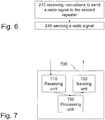
- FIG. 6 there is shown a flow chart of an exemplifying method in a first repeater 103 or relay 203 "first repeater" 103, 203 for contributing to radio characteristic determination, performed by a first node 101, of a radio link between the first repeater 103, 203 and at least one second repeater 104 or relay 204 "second repeater” 104, 204.
- a radio communication network comprises the first node 101, the first repeater 103, 203 and said at least one second repeater 104, 204.
- the first repeater 103, 203 is managed by the first node.
- the first repeater 103, 203 receives a first message from the first node 101, wherein the first message comprises instructions to the first repeater 103, 203 to send a radio signal being measureable by the second repeater 104, 204.
- the first repeater 103, 203 sends a radio signal in accordance with the instructions to said at least one second repeater 104, 204.
- another node is enabled to measure on the radio link between the first repeater and the other node itself.
- the characteristics of the radio signal is predetermined. Similar or same advantages and effects apply as for the corresponding method in the first node 101.
- the characteristics of the radio signal comprises transmission power. Similar or same advantages and effects apply as for the corresponding method in the first node 101.
- the radio signal is any data signal or a reference signal. Similar or same advantages and effects apply as for the corresponding method in the first node 101.
- FIG. 7 there is shown a schematic block diagram of an exemplifying arrangement 700 in a first repeater 103 or relay 203 "first repeater" 103, 203 for contributing to radio characteristic determination, performable by a first node 101, of a radio link between the first repeater 103, 203 and at least one second repeater 104 or relay 204 "second repeater” 104, 204.
- a radio communication network is arranged to comprise the first node 101, the first repeater 103, 203 and said at least one second repeater 104, 204.
- the first node 101 is arranged to manage the first repeater 103, 203.
- the arrangement comprises a receiving unit 710 configured to receive a first message from the first node 101, wherein the first message is configured to comprise instructions to the first repeater 103, 203 to send a radio signal being measureable by the second repeater 104, 204. Furthermore, the arrangement comprises a sending unit 720 configured to send a radio signal in accordance with the instructions to said at least one second repeater 104, 204.
- the characteristics of the radio signal is predetermined. Similar or same advantages and effects apply as for the corresponding method in the first node 101.
- the characteristics of the radio signal comprises transmission power. Similar or same advantages and effects apply as for the corresponding method in the first node 101.
- the radio signal is any data signal or a reference signal. Similar or same advantages and effects apply as for the corresponding method in the first node 101.
- Fig. 8 shows a flow chart of an exemplifying method in at least one second repeater 104 or relay 204 "second repeater" 104, 204 for contributing to radio characteristic determination, performed by a first node 101, of a radio link between a first repeater 103 or relay 203 "first repeater” 103, 203 and said at least one second repeater 104, 204.
- a radio communication network 100 comprises the first node 101, the first repeater 103, 203 and said at least one second repeater 104, 204.
- the first repeater 103, 203 is managed by the first node 101.
- the method comprises the following steps.
- said at least one second repeater 104, 204 receives a second message from the first node 101, wherein the second message comprises instructions to said at least one second repeater 104, 204 to measure on the radio signal to be received from the first repeater 103, 203.
- said at least one second repeater 104, 204 receives the radio signal from the first repeater 103, 203.
- 250 said at least one second repeater 104, 204 measures on the radio signal received from the first repeater 103, 203, thereby generating measurement data.
- said at least one second repeater 104, 204 sends the measurement data to the first node 101.
- said at least one second repeater 104, 204 is managed by the first node 101.
- the first and second repeater 103, 203, 104, 204 are controlled, or managed, by the same node 101.
- said at least one second repeater 104, 204 is managed by a second node 107.
- the radio communication network 100 further comprises the second node 107.
- the step of receiving 220 the second message is received via the second node from the first node 101.
- said at least one second repeater 104, 204 sends the measurement data via the second node 107 to the first node 101.
- measurement of cross couplings between repeaters controlled by different nodes 101, 107 is enabled.
- the radio communication network 100 comprises a third node 102, such as a communication device or a radio base station.
- the method may further comprise the following optional steps, which are illustrated as boxes drawn with a dashed line in Fig. 8 . 244
- said at least one second repeater 104, 204 receives from the third node 102 an information radio signal, comprising data, to be forwarded by said at least one second repeater.
- the information radio signal is transmitted on a data transmission resource, assigned to the third node 102 by the first node 101.
- said at least one second repeater 104, 204 sends the information radio signal to the first node 101.
- the information radio signal is, thus, transmitted on the data transmission resource, while suppressing, for example by filtering, the radio signal received from the first repeater 103, 203.
- the radio signal is transmitted on a measurement resource.
- the measurement and data transmission resources are orthogonal or near orthogonal resources, preferably non-overlapping in frequency.
- the characteristics of the radio signal is predetermined. Similar or same advantages and effects apply as for the corresponding method in the first node 101.
- the characteristics of the radio signal comprises transmission power. Similar or same advantages and effects apply as for the corresponding method in the first node 101.
- the radio signal is any data signal or a reference signal. Similar or same advantages and effects apply as for the corresponding method in the first node 101.
- Fig. 9 shows a schematic block diagram of an exemplifying arrangement 900 in at least one second repeater 104 or relay 204 "second repeater" 104, 204 for contributing to radio characteristic determination, performable by a first node 101, of a radio link between a first repeater 103 or relay 203 "first repeater" 103, 203 and said at least one second repeater 104, 204.
- a radio communication network 100 is arranged to comprise the first node 101, the first repeater 103, 203 and said at least one second repeater 104, 204.
- the first node 101 is configured to manage the first repeater 103, 203.
- the arrangement 900 comprises a receiving unit 910 configured to receive a second message from the first node 101, wherein the second message is configured to comprise instructions to said at least one second repeater 104, 204 to measure on the radio signal to be received from the first repeater 103, 203.
- the receiving unit 910 is further configured to receive the radio signal from the first repeater 103, 203.
- the arrangement 900 comprises a measuring unit 920 configured to measure on the radio signal receivable from the first repeater 103, 203, thereby being capable of generating measurement data.
- the arrangement 900 further comprises a sending unit 930 configured to send the measurement data to the first node 101.
- said at least one second repeater 104, 204 is managed by the first node 101.
- the first and second repeaters 103, 203, 104, 204 are managed, or controlled, by the same node.
- said at least one second repeater 104, 204 is managed by a second node 107.
- the radio communication network 100 further comprises the second node 107.
- the receiving unit 910 is configured to receive the second message via the second node 107 from the first node 101.
- the sending unit 930 is configured to send the measurement data via the second node 107 to the first node 101.
- the arrangement 900 is configured to handle measurement of cross couplings between repeaters controlled by different nodes, such as base stations. See Fig. 10 and 11 .
- the radio communication network 100 comprises a third node 102.
- the receiving unit 910 is further configured to receive from the third node 102 an information radio signal, comprising data, to be forwarded by said at least one second repeater, wherein the information radio signal is transmitted on a data transmission resource, assigned to the third node 102 by the first node 101.
- the sending unit 930 is configured to send the information radio signal to the first node 101, wherein the information radio signal is transmitted on the data transmission resource, while suppressing, for example by filtering, the radio signal received from the first repeater 103, 203, wherein the radio signal is transmitted on a measurement resource.
- the measurement and data transmission resources are orthogonal or near orthogonal resources, preferably non-overlapping in frequency.
- the characteristics of the radio signal is predetermined. Similar or same advantages and effects apply as for the corresponding method in the first node 101.
- the characteristics of the radio signal comprises transmission power. Similar or same advantages and effects apply as for the corresponding method in the first node 101.
- the radio signal is any data signal or a reference signal. Similar or same advantages and effects apply as for the corresponding method in the first node 101.
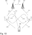
- Fig. 10 there is shown an overview of a radio communication network 300, comprising, in addition to the nodes and repeaters shown in Fig. 1 , a second node 107.
- the second node 107 controls or manages the second repeater 104.
- the repeaters 103 and 104 belong to or are associated with different nodes, i.e. the first and second node 101, 107, respectively. It may be noted that the repeaters in this example may be replaced by relays.
- the following uplink scenario may, as an example, illustrate the operation of the network according to Fig. 10 . It may, however, be noted that the present solution may be applicable for a downlink scenario as well.
- the third node 102 sends data directly to the first node 101, as indicated by an arrow 312. In addition or alternatively, the third node 102 sends data via the first repeater 103 to the first node 101, as indicated by arrows 316 and 313.
- When data is forwarded by the first repeater 103 it may happen that output from the first repeater 103, as indicated by arrow 315, is received by the second repeater 104, which in turn amplifies the incoming output.
- the first repeater 103 may enhance output from the second repeater 104, as indicated by an arrow 314.
- an undesired positive feedback loop that may destroy the communication between the third node 102 and the first node 101 is created.
- the arrows 317 and 311 represent interference in this uplink scenario.
- the second node 107 may send a message to the second repeater 104, wherein the message comprises instruction to the second repeater 104 to stop forwarding the interfering signal represented by arrow 311.
- an arrow 310 represents information exchange between the first and second nodes 101, 107.
- the information exchange relates to a message from the first node 101 to the second node 107, wherein the message comprises instructions to the second node 107 to instruct the second repeater 104 to measure on the radio signal.
- the information exchange relates to a message from the second node 107 to the first node 101, wherein the message comprises a measurement report from the second repeater 104.
- Fig. 11 there is shown a schematic combined flow chart and signaling diagram of an embodiment of the method performed in the radio communication network 300 according to Fig. 10 .
- the first node 101 sends a first message to the first repeater 103, 203, wherein the first message comprises instructions to the first repeater 103, 203 to send a radio signal being measureable by the second repeater 104, 204 for measurement purposes.
- a first message is sent from the first node 101 sends to the second node 107, wherein the first message comprises instructions to instruct the second repeater 104, 204 to measure on the radio signal.
- an acknowledgement message is sent from the second node 107 to the first node 101.
- a second message is sent from the second node 107 to said at least one second repeater 104, 204, wherein the second message comprises instructions to said at least one second repeater 104, 204 to measure on the radio signal to be received from the first repeater 103, 203.
- This message typically includes a reference signal descriptor and possibly also an uplink resource for transmission of the measurement results back to the base station.
- the behavior of the measuring repeater may be specified in this message. Examples of behaviors are if the measuring repeater shall suppress the measurement signal or not, for example by means of filtering.
- the first repeater 103, 203 sends a radio signal in accordance with the instructions to said at least one second repeater 104, 204.
- the second repeater 104, 204 measures on the radio signal received from the first repeater 103, 203, thereby generating measurement data.
- the measuring repeater 104 may be configured to measure and calculate the reference signal received power (RSRP).
- the first node 101 and/or the second node 107 measure(s) the radio signal sent by the first repeater 103, 203, generate(s) node measurement data based on the measurement of the radio signal, and determine(s) radio characteristics of a second radio link between the first repeater 103, 203 and the first node 101, based on the node measurement data.
- the second node 107 receives measurement data (or a measurement report) from said at least one second repeater 104, 204, wherein the measurement data is measured by said at least one second repeater 104, 204 and is measured on the radio signal received from the first repeater 103, 203.
- the measurement data is sent from the second node 107 to the first node 101.
- the first node 101 sends an acknowledgement to the second node 107.
- the second node 107 sends an acknowledgement to the second repeater 104, 204.
- the first node 101 determines radio characteristics of the radio link between the first repeater 103, 203 and said at least one second repeater 104, 204 based on the measurement data.
- Fig. 12 shows a flow chart of an exemplifying method in a second node 107 for supplying measurement data to a first node 101 performing radio characteristic determination of a radio link between a first repeater 103 or relay 203 "first repeater” 103, 203 and at least one second repeater 104 or relay 204 "second repeater” 104, 204.
- a radio signal is sent from the first repeater 103, 203 and is measureable by said at least one second repeater 104, 204.
- the first repeater and said at least one second repeater are managed by the first and second nodes, respectively.
- a radio communication network 300 comprises the first and second nodes 101, 107 and the first and said at least one second repeater 103, 203, 104, 204.
- the method comprises the following steps. 221
- the second node 107 receives a first message from the first node 101, wherein the first message comprises instructions to instruct said at least one second repeater 104, 204 to measure on the radio signal.
- the second node 107 sends a second message to said at least one second repeater 104, 204, wherein the second message comprises instructions to said at least one second repeater 104, 204 to measure on the radio signal to be received from the first repeater 103, 203.
- the second node 107 receives measurement data from said at least one second repeater 104, 204, wherein the measurement data is measured by said at least one second repeater 104, 204 and is measured on the radio signal received from the first repeater 103, 203. 261 In a step 261, the second node 107 sends the measurement data to the first node, thereby supplying measurement data to the first node 101 determining radio characteristics of the radio link.
- the characteristics of the radio signal is predetermined. Similar or same advantages and effects apply as for the corresponding method in the first node 101.
- the characteristics of the radio signal comprises transmission power. Similar or same advantages and effects apply as for the corresponding method in the first node 101.
- the radio signal is any data signal or a reference signal. Similar or same advantages and effects apply as for the corresponding method in the first node 101.
- FIG. 13 there is shown a schematic block diagram of an embodiment of the arrangement 1300 in a second node 107 for supplying measurement data to a first node 101 arranged to perform radio characteristic determination of a radio link between a first repeater 103 or relay 203 "first repeater" 103, 203 and at least one second repeater 104 or relay 204 "second repeater” 104, 204.
- a radio signal is sendable from the first repeater 103, 203 and is measureable by said at least one second repeater 104, 204.
- Each of the first and second nodes is configured to manage the first repeater and said at least one second repeater, respectively.
- a radio communication network 300 is arranged to comprise the first and second nodes 101, 107 and the first and said at least one second repeaters 103, 203, 104, 204.
- the arrangement 1300 comprises a receiving unit 1310 configured to receive a first message from the first node 101, wherein the first message is configured to comprise instructions to instruct said at least one second repeater 104, 204 to measure on the radio signal.
- the arrangement 1300 comprises a sending unit 1320 configured to send a second message to said at least one second repeater 104, 204, wherein the second message is configured to comprise instructions to said at least one second repeater 104, 204 to measure on the radio signal receivable from the first repeater 103, 203.
- the receiving unit 1310 is further configured to receive measurement data from said at least one second repeater 104, 204, wherein the measurement data is measurable by said at least one second repeater 104, 204 and is measurable on the radio signal received from the first repeater 103, 203.
- the sending unit 1320 is configured to send the measurement data to the first node, thereby being configured to supply measurement data to the first node 101 being configured to determine radio characteristics of the radio link.
- the characteristics of the radio signal is predetermined. Similar or same advantages and effects apply as for the corresponding method in the first node 101.
- the characteristics of the radio signal comprises transmission power. Similar or same advantages and effects apply as for the corresponding method in the first node 101.
- the radio signal is any data signal or a reference signal. Similar or same advantages and effects apply as for the corresponding method in the first node 101.
Landscapes
- Engineering & Computer Science (AREA)
- Computer Networks & Wireless Communication (AREA)
- Signal Processing (AREA)
- Mobile Radio Communication Systems (AREA)
- Radio Relay Systems (AREA)
Claims (6)
- Verfahren in einem ersten Knoten (101) zur Bestimmung von Funkeigenschaften einer Funkstrecke zwischen einem ersten Repeater (103) und mindestens einem zweiten Repeater (104), wobei der erste Repeater von dem ersten Knoten gesteuert wird, wobei der erste und zweite Repeater (103, 104) Einschaltfrequenz-Repeater sind, wobei der erste Knoten (101), der erste Repeater (103, 203) und der mindestens eine zweite Repeater (104, 204) in einem Long-Term-Evolution-Netzwerk (100) enthalten sind, wobei das Verfahren Folgendes umfasst:Senden (210) einer ersten Nachricht an den ersten Repeater (103, 203), wobei die erste Nachricht Anweisungen an den ersten Repeater (103, 203) umfasst, ein Funksignal zu senden, das von dem zweiten Repeater (104, 204) gemessen werden kann, wobei das Funksignal ein beliebiges Datensignal oder ein Referenzsignal ist,Senden (220) einer zweiten Nachricht an den mindestens einen zweiten Repeater (104, 204), wobei die zweite Nachricht Anweisungen an den mindestens einen zweiten Repeater (104, 204) umfasst, an dem Funksignal zu messen, das von dem ersten Repeater (103, 203) empfangen werden soll,Empfangen (260) von Messdaten von dem mindestens einen zweiten Repeaters (104, 204), wobei die Messdaten von dem mindestens einen zweiten Repeater (104, 204) gemessen werden und an dem Funksignal gemessen werden, das von dem ersten Repeater (103, 203) empfangen wird,Bestimmen (280) der Funkeigenschaften der Funkstrecke zwischen dem ersten Repeater (103, 203) und dem mindestens einen zweiten Repeater (104, 204), basierend auf den Messdaten, wobeidie Anweisungen an den ersten Repeater ferner Anweisungen umfassen, dem ersten Repeater eine Messressource zuzuweisen, und die Methode ferner umfasst:Senden (208) einer vierten Nachricht an ein Kommunikationsgerät (102), das in dem Long-Term-Evolution-Netzwerk (100) enthalten ist, wobei die vierte Nachricht Anweisungen an das Kommunikationsgerät (102) enthält, dem Kommunikationsgerät (102) eine Datenübertragungs-Ressource zuzuweisen, wobei die Mess- und Datenübertragungs-Ressourcen orthogonale oder nahezu orthogonale Ressourcen sind, die sich in der Frequenz nicht überlappen.
- Verfahren nach Anspruch 1, wobei das Long-Term-Evolution-Netzwerk (100) einen zweiten Knoten (107) umfasst, wobei der mindestens eine zweite Repeater (104, 204) von dem zweiten Knoten (107) gesteuert wird, wobei der Schritt des Sendens der zweiten Nachricht durch den zweiten Knoten (107) gesendet wird.
- Verfahren nach einem der vorgehenden Ansprüche, wobei die Eigenschaften des Funksignals vorbestimmt sind.
- Verfahren nach einem der vorgehenden Ansprüche, wobei die Eigenschaften des Funksignals eine Übertragungsleistung umfassen.
- Verfahren nach einem der vorgehenden Ansprüche, ferner umfassend:Messen (251) des Funksignals, das von dem ersten Repeater (103, 203) gesendet wird,Erzeugen von Knoten-Messdaten, basierend auf der Messung des Funksignals, undBestimmen von Funkeigenschaften einer zweiten Funkstrecke zwischen dem ersten Repeater (103, 203) und dem ersten Knoten (101), basierend auf den Knoten-Messdaten.
- Anordnung (500) in einem ersten Knoten (101) zur Bestimmung der Funkeigenschaften einer Funkstrecke zwischen einem ersten Repeater (103) und mindestens einem zweiten Repeater (104), wobei der erste Knoten so konfiguriert ist, dass er den ersten Repeater steuert, wobei der erste und zweite Repeater (103, 104) Einschaltfrequenz-Repeater sind, wobei ein Long-Term-Evolution-Netzwerk (100) so eingerichtet ist, dass es den ersten Knoten (101), den ersten Repeater (103, 203) und den mindestens einen zweiten Repeater (104, 204) umfasst, wobei die Anordnung Folgendes umfasst:eine Sendeeinheit (510), die so konfiguriert ist, dass sie eine erste Nachricht an den ersten Repeater (103, 203) sendet, wobei die erste Nachricht so konfiguriert ist, dass sie Anweisungen an den ersten Repeater (103, 203) umfasst, ein Funksignal zu senden, das von dem zweiten Repeater (104, 204) messbar ist, wobei das Funksignal ein beliebiges Datensignal oder ein Referenzsignal ist, wobei die Sendeeinheit (510) ferner so konfiguriert ist, dass sie eine zweite Nachricht an den mindestens einen zweiten Repeater (104, 204) sendet, wobei die zweite Nachricht so konfiguriert ist, dass sie Anweisungen an den mindestens einen zweiten Repeater (104, 204) umfasst, an dem Funksignal zu messen, das von dem ersten Repeater (103, 203) empfangen werden soll, wobeidie Anweisungen an den ersten Repeater ferner Anweisungen umfassen, dem ersten Repeater eine Messressource zuzuweisen, und wobei die Sendeeinheit (510) ferner so konfiguriert ist, dass sie eine vierte Nachricht an ein Kommunikationsgerät (102) sendet, das in dem Long-Term-Evolution-Netzwerk (100) enthalten ist, wobei die vierte Nachricht Anweisungen an das Kommunikationsgerät (102) umfasst, dem Kommunikationsgerät (102) eine Datenübertragungs-Ressource zuzuweisen, wobei die Mess- und Datenübertragungs-Ressourcen orthogonale oder nahezu orthogonale Ressourcen sind, die sich in der Frequenz nicht überlappen,eine Empfangseinheit (520), die so konfiguriert ist, dass sie Daten von dem mindestens einen zweiten Repeater (104, 204) misst, wobei die Messdaten von dem mindestens einen zweiten Repeater (104, 204) gemessen werden können und auf dem Funksignal gemessen werden können, das von dem ersten Repeater (103, 203) empfangen wird, undeine Bestimmungseinheit (530), die so konfiguriert ist, dass sie Funkeigenschaften der Funkstrecke zwischen dem ersten Repeater (103, 203) und dem mindestens einen zweiten Repeater (104, 204) basierend auf den Messdaten bestimmt.
Applications Claiming Priority (1)
| Application Number | Priority Date | Filing Date | Title |
|---|---|---|---|
| PCT/SE2008/051324 WO2010059083A1 (en) | 2008-11-18 | 2008-11-18 | Methods and arrangements for determining radio characteristics of a radio link |
Publications (2)
| Publication Number | Publication Date |
|---|---|
| EP2374225A1 EP2374225A1 (de) | 2011-10-12 |
| EP2374225B1 true EP2374225B1 (de) | 2018-01-10 |
Family
ID=40957768
Family Applications (1)
| Application Number | Title | Priority Date | Filing Date |
|---|---|---|---|
| EP08876295.0A Not-in-force EP2374225B1 (de) | 2008-11-18 | 2008-11-18 | Verfahren und anordnungen zur bestimmung der funkeigenschaften einer funkstrecke |
Country Status (4)
| Country | Link |
|---|---|
| US (1) | US8699942B2 (de) |
| EP (1) | EP2374225B1 (de) |
| JP (1) | JP5296883B2 (de) |
| WO (1) | WO2010059083A1 (de) |
Families Citing this family (8)
| Publication number | Priority date | Publication date | Assignee | Title |
|---|---|---|---|---|
| CN101873690A (zh) * | 2009-04-22 | 2010-10-27 | 北京三星通信技术研究有限公司 | 定位移动终端的方法、系统及装置 |
| JP5540592B2 (ja) | 2009-07-23 | 2014-07-02 | ソニー株式会社 | 通信システム、通信制御方法、移動端末、および中継装置 |
| WO2013125226A1 (en) * | 2012-02-24 | 2013-08-29 | Nec Corporation | Radio communication system and communication method |
| JP6115227B2 (ja) * | 2013-03-22 | 2017-04-19 | 富士通株式会社 | 送信電力決定装置 |
| EP2966906B1 (de) | 2013-04-03 | 2019-08-07 | Huawei Technologies Co., Ltd. | Verfahren und vorrichtung zur verarbeitung von downlink-informationen |
| US10879994B2 (en) * | 2019-05-10 | 2020-12-29 | AR & NS Investment, LLC | Repeater system and method for high-performance communication |
| US11166222B2 (en) * | 2019-08-02 | 2021-11-02 | AR & NS Investment, LLC | Communication by a repeater system including a network of radio frequency (RF) repeater devices |
| WO2021076337A1 (en) * | 2019-10-16 | 2021-04-22 | Commscope Technologies Llc | System and method for communicating between a radio and a virtual baseband unit which are incompatible |
Family Cites Families (16)
| Publication number | Priority date | Publication date | Assignee | Title |
|---|---|---|---|---|
| JP4052835B2 (ja) * | 2001-12-28 | 2008-02-27 | 株式会社日立製作所 | 多地点中継を行う無線伝送システム及びそれに使用する無線装置 |
| CN1826780B (zh) * | 2003-05-28 | 2010-04-28 | 艾利森电话股份有限公司 | 用于使用协同中继的无线通信网络的方法和结构 |
| US7480486B1 (en) * | 2003-09-10 | 2009-01-20 | Sprint Spectrum L.P. | Wireless repeater and method for managing air interface communications |
| JP4670106B2 (ja) * | 2005-08-12 | 2011-04-13 | ケイティー コーポレーション | 室内rf中継器のリンクアンテナ設置位置選定方法、ケーブル装置及び端末機 |
| JP4847540B2 (ja) | 2005-11-29 | 2011-12-28 | テレフオンアクチーボラゲット エル エム エリクソン(パブル) | 無線マルチホップ中継ネットワークにおけるスケジューリング |
| US7796025B2 (en) * | 2006-03-27 | 2010-09-14 | Current Technologies, Llc | Power line communication device and method |
| US7917149B2 (en) | 2006-08-18 | 2011-03-29 | Fujitsu Limited | System and method for reusing wireless resources in a wireless network |
| JP2008079226A (ja) * | 2006-09-25 | 2008-04-03 | Mitsubishi Electric Corp | 無線通信システムおよび無線通信方法 |
| GB2443231B (en) * | 2006-10-04 | 2011-02-02 | Vodafone Plc | Configuration of base station repeater |
| EP1940189B1 (de) * | 2006-12-27 | 2020-04-15 | Samsung Electronics Co., Ltd. | Vorrichtung und Verfahren zum Berechnen einer Ressourcenzuordnung einer Relaisstation |
| US20080165881A1 (en) | 2007-01-08 | 2008-07-10 | Zhifeng Tao | Method for Accessing Channels in OFDMA Mobile Multihop Relay Networks |
| US8270908B2 (en) * | 2007-01-08 | 2012-09-18 | Nokia Corporation | Power control and channel reuse techniques for wireless relay networks |
| JP4855962B2 (ja) * | 2007-02-06 | 2012-01-18 | 富士通株式会社 | 無線通信システム、及び無線通信方法 |
| JP2012521120A (ja) * | 2009-03-20 | 2012-09-10 | テレフオンアクチーボラゲット エル エム エリクソン(パブル) | 改良型中継器 |
| EP2428079B1 (de) * | 2009-05-04 | 2018-09-12 | Telefonaktiebolaget LM Ericsson (publ) | Bestimmung der repeater-verstärkung in abhängigkeit von interferenz |
| JP5213911B2 (ja) * | 2010-06-08 | 2013-06-19 | 株式会社日立製作所 | 光中継システム |
-
2008
- 2008-11-18 EP EP08876295.0A patent/EP2374225B1/de not_active Not-in-force
- 2008-11-18 WO PCT/SE2008/051324 patent/WO2010059083A1/en not_active Ceased
- 2008-11-18 JP JP2011536280A patent/JP5296883B2/ja not_active Expired - Fee Related
- 2008-11-18 US US13/129,778 patent/US8699942B2/en not_active Expired - Fee Related
Also Published As
| Publication number | Publication date |
|---|---|
| JP5296883B2 (ja) | 2013-09-25 |
| EP2374225A1 (de) | 2011-10-12 |
| US20110223855A1 (en) | 2011-09-15 |
| WO2010059083A1 (en) | 2010-05-27 |
| JP2012509611A (ja) | 2012-04-19 |
| US8699942B2 (en) | 2014-04-15 |
Similar Documents
| Publication | Publication Date | Title |
|---|---|---|
| US11902220B2 (en) | Repeater methods and apparatus | |
| US8699942B2 (en) | Methods and arrangements for determining radio characteristics of a radio link | |
| US8345587B2 (en) | Relay station, base station and method for extending a coverage area of a base station in a radio network | |
| CN102948089B (zh) | 无线通信网络中的方法和装置 | |
| US11509391B2 (en) | Adaptive multiple access scheme in integrated access and backhaul networks | |
| US8200274B2 (en) | Method of controlling power of access uplink using relay station and system thereof | |
| US20080285499A1 (en) | System and Method for Unbalanced Relay-Based Wireless Communications | |
| CN101997593B (zh) | 自适应中继方式择优选择方法和中继节点 | |
| CA2743099C (en) | Creation and signalling of ue lists to support frequency selective repeater operation | |
| CN110943848A (zh) | 一种用于无线网络和多个ue之间的虚拟通信的方法 | |
| US11177873B2 (en) | Adaptive relaying in a non-orthogonal multiple access (NOMA) communication system | |
| US20130102307A1 (en) | Radio base station apparatus, mobile terminal device, and cell selecting method | |
| US20250358636A1 (en) | Initial beam management for network controlled repeater deployments | |
| US20250088261A1 (en) | Telecommunications apparatus and methods | |
| KR101207179B1 (ko) | 채널 리소스를 재이용하는 무선 통신 방법, 시스템, 및 장치 | |
| KR101938113B1 (ko) | 협력적 비직교다중접속 상향링크에서 조직적 직접 및 중계전송 연계기술 | |
| US20260032558A1 (en) | Coexistence of u2u discovery and u2n discovery | |
| WO2011013410A1 (ja) | マルチホップ無線通信システム、制御装置、中継局、および制御方法 | |
| Kakitani et al. | Comparing the energy efficiency of single-hop, multi-hop and incremental decode-and-forward in multi-relay wireless sensor networks | |
| Shrestha et al. | New approaches for relay selection in IEEE 802.16 mobile multi-hop relay networks | |
| US20190058520A1 (en) | Control signaling for the relay scenarios | |
| Majhi et al. | Secondary outage analysis of amplify-and-forward cognitive relays with direct link and primary interference | |
| US20260046665A1 (en) | Beam pair determination for the forward link of network-controlled repeater | |
| Bao et al. | Optimal switching adaptive m-qam for opportunistic amplify-and-forward networks | |
| TWI501578B (zh) | 行動通訊系統、無線中繼裝置、行動通訊裝置、及無線通訊方法 |
Legal Events
| Date | Code | Title | Description |
|---|---|---|---|
| PUAI | Public reference made under article 153(3) epc to a published international application that has entered the european phase |
Free format text: ORIGINAL CODE: 0009012 |
|
| 17P | Request for examination filed |
Effective date: 20110420 |
|
| AK | Designated contracting states |
Kind code of ref document: A1 Designated state(s): AT BE BG CH CY CZ DE DK EE ES FI FR GB GR HR HU IE IS IT LI LT LU LV MC MT NL NO PL PT RO SE SI SK TR |
|
| DAX | Request for extension of the european patent (deleted) | ||
| 17Q | First examination report despatched |
Effective date: 20130924 |
|
| REG | Reference to a national code |
Ref country code: DE Ref legal event code: R079 Ref document number: 602008053716 Country of ref document: DE Free format text: PREVIOUS MAIN CLASS: H04B0007150000 Ipc: H04B0007155000 |
|
| GRAP | Despatch of communication of intention to grant a patent |
Free format text: ORIGINAL CODE: EPIDOSNIGR1 |
|
| RIC1 | Information provided on ipc code assigned before grant |
Ipc: H04B 7/155 20060101AFI20170726BHEP |
|
| INTG | Intention to grant announced |
Effective date: 20170808 |
|
| GRAS | Grant fee paid |
Free format text: ORIGINAL CODE: EPIDOSNIGR3 |
|
| GRAA | (expected) grant |
Free format text: ORIGINAL CODE: 0009210 |
|
| AK | Designated contracting states |
Kind code of ref document: B1 Designated state(s): AT BE BG CH CY CZ DE DK EE ES FI FR GB GR HR HU IE IS IT LI LT LU LV MC MT NL NO PL PT RO SE SI SK TR |
|
| REG | Reference to a national code |
Ref country code: GB Ref legal event code: FG4D |
|
| REG | Reference to a national code |
Ref country code: CH Ref legal event code: EP Ref country code: AT Ref legal event code: REF Ref document number: 963513 Country of ref document: AT Kind code of ref document: T Effective date: 20180115 |
|
| REG | Reference to a national code |
Ref country code: IE Ref legal event code: FG4D |
|
| REG | Reference to a national code |
Ref country code: DE Ref legal event code: R096 Ref document number: 602008053716 Country of ref document: DE |
|
| REG | Reference to a national code |
Ref country code: NL Ref legal event code: MP Effective date: 20180110 |
|
| REG | Reference to a national code |
Ref country code: AT Ref legal event code: MK05 Ref document number: 963513 Country of ref document: AT Kind code of ref document: T Effective date: 20180110 |
|
| PG25 | Lapsed in a contracting state [announced via postgrant information from national office to epo] |
Ref country code: NL Free format text: LAPSE BECAUSE OF FAILURE TO SUBMIT A TRANSLATION OF THE DESCRIPTION OR TO PAY THE FEE WITHIN THE PRESCRIBED TIME-LIMIT Effective date: 20180110 |
|
| PG25 | Lapsed in a contracting state [announced via postgrant information from national office to epo] |
Ref country code: FI Free format text: LAPSE BECAUSE OF FAILURE TO SUBMIT A TRANSLATION OF THE DESCRIPTION OR TO PAY THE FEE WITHIN THE PRESCRIBED TIME-LIMIT Effective date: 20180110 Ref country code: LT Free format text: LAPSE BECAUSE OF FAILURE TO SUBMIT A TRANSLATION OF THE DESCRIPTION OR TO PAY THE FEE WITHIN THE PRESCRIBED TIME-LIMIT Effective date: 20180110 Ref country code: CY Free format text: LAPSE BECAUSE OF FAILURE TO SUBMIT A TRANSLATION OF THE DESCRIPTION OR TO PAY THE FEE WITHIN THE PRESCRIBED TIME-LIMIT Effective date: 20180110 Ref country code: ES Free format text: LAPSE BECAUSE OF FAILURE TO SUBMIT A TRANSLATION OF THE DESCRIPTION OR TO PAY THE FEE WITHIN THE PRESCRIBED TIME-LIMIT Effective date: 20180110 Ref country code: NO Free format text: LAPSE BECAUSE OF FAILURE TO SUBMIT A TRANSLATION OF THE DESCRIPTION OR TO PAY THE FEE WITHIN THE PRESCRIBED TIME-LIMIT Effective date: 20180410 Ref country code: HR Free format text: LAPSE BECAUSE OF FAILURE TO SUBMIT A TRANSLATION OF THE DESCRIPTION OR TO PAY THE FEE WITHIN THE PRESCRIBED TIME-LIMIT Effective date: 20180110 |
|
| PG25 | Lapsed in a contracting state [announced via postgrant information from national office to epo] |
Ref country code: IS Free format text: LAPSE BECAUSE OF FAILURE TO SUBMIT A TRANSLATION OF THE DESCRIPTION OR TO PAY THE FEE WITHIN THE PRESCRIBED TIME-LIMIT Effective date: 20180510 Ref country code: BG Free format text: LAPSE BECAUSE OF FAILURE TO SUBMIT A TRANSLATION OF THE DESCRIPTION OR TO PAY THE FEE WITHIN THE PRESCRIBED TIME-LIMIT Effective date: 20180410 Ref country code: AT Free format text: LAPSE BECAUSE OF FAILURE TO SUBMIT A TRANSLATION OF THE DESCRIPTION OR TO PAY THE FEE WITHIN THE PRESCRIBED TIME-LIMIT Effective date: 20180110 Ref country code: SE Free format text: LAPSE BECAUSE OF FAILURE TO SUBMIT A TRANSLATION OF THE DESCRIPTION OR TO PAY THE FEE WITHIN THE PRESCRIBED TIME-LIMIT Effective date: 20180110 Ref country code: LV Free format text: LAPSE BECAUSE OF FAILURE TO SUBMIT A TRANSLATION OF THE DESCRIPTION OR TO PAY THE FEE WITHIN THE PRESCRIBED TIME-LIMIT Effective date: 20180110 Ref country code: GR Free format text: LAPSE BECAUSE OF FAILURE TO SUBMIT A TRANSLATION OF THE DESCRIPTION OR TO PAY THE FEE WITHIN THE PRESCRIBED TIME-LIMIT Effective date: 20180411 Ref country code: PL Free format text: LAPSE BECAUSE OF FAILURE TO SUBMIT A TRANSLATION OF THE DESCRIPTION OR TO PAY THE FEE WITHIN THE PRESCRIBED TIME-LIMIT Effective date: 20180110 |
|
| REG | Reference to a national code |
Ref country code: DE Ref legal event code: R097 Ref document number: 602008053716 Country of ref document: DE |
|
| PG25 | Lapsed in a contracting state [announced via postgrant information from national office to epo] |
Ref country code: IT Free format text: LAPSE BECAUSE OF FAILURE TO SUBMIT A TRANSLATION OF THE DESCRIPTION OR TO PAY THE FEE WITHIN THE PRESCRIBED TIME-LIMIT Effective date: 20180110 Ref country code: EE Free format text: LAPSE BECAUSE OF FAILURE TO SUBMIT A TRANSLATION OF THE DESCRIPTION OR TO PAY THE FEE WITHIN THE PRESCRIBED TIME-LIMIT Effective date: 20180110 Ref country code: RO Free format text: LAPSE BECAUSE OF FAILURE TO SUBMIT A TRANSLATION OF THE DESCRIPTION OR TO PAY THE FEE WITHIN THE PRESCRIBED TIME-LIMIT Effective date: 20180110 |
|
| PLBE | No opposition filed within time limit |
Free format text: ORIGINAL CODE: 0009261 |
|
| STAA | Information on the status of an ep patent application or granted ep patent |
Free format text: STATUS: NO OPPOSITION FILED WITHIN TIME LIMIT |
|
| PG25 | Lapsed in a contracting state [announced via postgrant information from national office to epo] |
Ref country code: DK Free format text: LAPSE BECAUSE OF FAILURE TO SUBMIT A TRANSLATION OF THE DESCRIPTION OR TO PAY THE FEE WITHIN THE PRESCRIBED TIME-LIMIT Effective date: 20180110 Ref country code: SK Free format text: LAPSE BECAUSE OF FAILURE TO SUBMIT A TRANSLATION OF THE DESCRIPTION OR TO PAY THE FEE WITHIN THE PRESCRIBED TIME-LIMIT Effective date: 20180110 Ref country code: CZ Free format text: LAPSE BECAUSE OF FAILURE TO SUBMIT A TRANSLATION OF THE DESCRIPTION OR TO PAY THE FEE WITHIN THE PRESCRIBED TIME-LIMIT Effective date: 20180110 |
|
| 26N | No opposition filed |
Effective date: 20181011 |
|
| PG25 | Lapsed in a contracting state [announced via postgrant information from national office to epo] |
Ref country code: SI Free format text: LAPSE BECAUSE OF FAILURE TO SUBMIT A TRANSLATION OF THE DESCRIPTION OR TO PAY THE FEE WITHIN THE PRESCRIBED TIME-LIMIT Effective date: 20180110 |
|
| REG | Reference to a national code |
Ref country code: CH Ref legal event code: PL |
|
| PG25 | Lapsed in a contracting state [announced via postgrant information from national office to epo] |
Ref country code: LU Free format text: LAPSE BECAUSE OF NON-PAYMENT OF DUE FEES Effective date: 20181118 Ref country code: MC Free format text: LAPSE BECAUSE OF FAILURE TO SUBMIT A TRANSLATION OF THE DESCRIPTION OR TO PAY THE FEE WITHIN THE PRESCRIBED TIME-LIMIT Effective date: 20180110 |
|
| REG | Reference to a national code |
Ref country code: BE Ref legal event code: MM Effective date: 20181130 |
|
| REG | Reference to a national code |
Ref country code: IE Ref legal event code: MM4A |
|
| PG25 | Lapsed in a contracting state [announced via postgrant information from national office to epo] |
Ref country code: CH Free format text: LAPSE BECAUSE OF NON-PAYMENT OF DUE FEES Effective date: 20181130 Ref country code: LI Free format text: LAPSE BECAUSE OF NON-PAYMENT OF DUE FEES Effective date: 20181130 |
|
| PG25 | Lapsed in a contracting state [announced via postgrant information from national office to epo] |
Ref country code: IE Free format text: LAPSE BECAUSE OF NON-PAYMENT OF DUE FEES Effective date: 20181118 |
|
| PG25 | Lapsed in a contracting state [announced via postgrant information from national office to epo] |
Ref country code: BE Free format text: LAPSE BECAUSE OF NON-PAYMENT OF DUE FEES Effective date: 20181130 |
|
| PG25 | Lapsed in a contracting state [announced via postgrant information from national office to epo] |
Ref country code: MT Free format text: LAPSE BECAUSE OF NON-PAYMENT OF DUE FEES Effective date: 20181118 |
|
| PG25 | Lapsed in a contracting state [announced via postgrant information from national office to epo] |
Ref country code: TR Free format text: LAPSE BECAUSE OF FAILURE TO SUBMIT A TRANSLATION OF THE DESCRIPTION OR TO PAY THE FEE WITHIN THE PRESCRIBED TIME-LIMIT Effective date: 20180110 |
|
| PG25 | Lapsed in a contracting state [announced via postgrant information from national office to epo] |
Ref country code: PT Free format text: LAPSE BECAUSE OF FAILURE TO SUBMIT A TRANSLATION OF THE DESCRIPTION OR TO PAY THE FEE WITHIN THE PRESCRIBED TIME-LIMIT Effective date: 20180110 |
|
| PG25 | Lapsed in a contracting state [announced via postgrant information from national office to epo] |
Ref country code: HU Free format text: LAPSE BECAUSE OF FAILURE TO SUBMIT A TRANSLATION OF THE DESCRIPTION OR TO PAY THE FEE WITHIN THE PRESCRIBED TIME-LIMIT; INVALID AB INITIO Effective date: 20081118 |
|
| PGFP | Annual fee paid to national office [announced via postgrant information from national office to epo] |
Ref country code: DE Payment date: 20201127 Year of fee payment: 13 Ref country code: GB Payment date: 20201127 Year of fee payment: 13 Ref country code: FR Payment date: 20201125 Year of fee payment: 13 |
|
| REG | Reference to a national code |
Ref country code: DE Ref legal event code: R119 Ref document number: 602008053716 Country of ref document: DE |
|
| GBPC | Gb: european patent ceased through non-payment of renewal fee |
Effective date: 20211118 |
|
| PG25 | Lapsed in a contracting state [announced via postgrant information from national office to epo] |
Ref country code: GB Free format text: LAPSE BECAUSE OF NON-PAYMENT OF DUE FEES Effective date: 20211118 Ref country code: DE Free format text: LAPSE BECAUSE OF NON-PAYMENT OF DUE FEES Effective date: 20220601 |
|
| PG25 | Lapsed in a contracting state [announced via postgrant information from national office to epo] |
Ref country code: FR Free format text: LAPSE BECAUSE OF NON-PAYMENT OF DUE FEES Effective date: 20211130 |