EP2374344B1 - Tête de découpage d'installation agricole avec guide-chaîne flexible ajustable vers l'avant et l'arrière doté d'un réglage de préchargement automatique - Google Patents
Tête de découpage d'installation agricole avec guide-chaîne flexible ajustable vers l'avant et l'arrière doté d'un réglage de préchargement automatique Download PDFInfo
- Publication number
- EP2374344B1 EP2374344B1 EP11161183.6A EP11161183A EP2374344B1 EP 2374344 B1 EP2374344 B1 EP 2374344B1 EP 11161183 A EP11161183 A EP 11161183A EP 2374344 B1 EP2374344 B1 EP 2374344B1
- Authority
- EP
- European Patent Office
- Prior art keywords
- cutterbar
- fore
- aft
- header
- floor
- Prior art date
- Legal status (The legal status is an assumption and is not a legal conclusion. Google has not performed a legal analysis and makes no representation as to the accuracy of the status listed.)
- Active
Links
Images




Classifications
-
- A—HUMAN NECESSITIES
- A01—AGRICULTURE; FORESTRY; ANIMAL HUSBANDRY; HUNTING; TRAPPING; FISHING
- A01D—HARVESTING; MOWING
- A01D41/00—Combines, i.e. harvesters or mowers combined with threshing devices
- A01D41/12—Details of combines
- A01D41/14—Mowing tables
- A01D41/141—Automatic header control
Definitions
- This invention relates generally to a header for an agricultural plant cutting machine, and more particularly, to a header with a fore and aft adjustable flexible cutterbar and which automatically adjusts a preload force exerted against the cutterbar as a function of the fore and aft position thereof.
- An agricultural plant cutting machine such as, but not limited to, a combine or a windrower generally includes a header operable for severing and collecting or gathering plant or crop material as the machine is driven over a field.
- the header will have a plant cutting cutterbar for severing the plants or crops, which will typically comprise an elongate sickle mechanism sidewardly reciprocatingly movable relative to a non-reciprocating guard structure.
- the cutterbar and guard structure are flexible, that is, capable of flexing upwardly and downwardly at locations along the width of the header, to facilitate operation while in contact with the ground along the width of the header, and while enabling conforming to and accommodating irregularities and unevenness in the ground surface.
- a flexible cutterbar is supported at spaced locations along its length on forward ends of pivoting support arms having rear ends which pivotally connect to the header.
- the individual pivotability of the support arms enables the respective locations of the cutterbar to flex individually, downwardly and upwardly for conforming to or accommodating ground surface irregularities, and, if the header is equipped with an automatic height control system, for triggering operation of that system.
- a ground contour following capability of a flexible cutterbar can be enhanced by exerting a preload force against it, for example, to reduce the amount of applied external force required to move the support arm and supported portion of the cutterbar upwardly. This is desirable and advantageous, as it can improve the cutterbar flex reaction to upwardly extending ground irregularities and increased firmness and hardness, resulting in smoother operation with less jarring. It can also act to limit the downward flexure of the cutterbar into ground depressions and the like.
- the cutterbar it is desirable for the cutterbar to be adjustably movable also in a fore and aft direction in relation to crop gathering and collecting apparatus such as a reel and an auger or draper belt of the header, for adapting to different crop varieties and conditions.
- the effect of the preload e.g., ground following characteristics
- the cutterbar is moved in the forward direction, the center of gravity thereof may be moved more distant from the pivot point, thus reducing the preload effect.
- the cutterbar is retracted, the effective preload may be increased.
- Document EP2055173 A1 discloses a header according to the preamble of claim 1 for an agricultural harvesting machine such as a combine with a control system to automatically maintain a desired positional relationship of the reel to the cutter bar.
- a header with a fore and aft adjustable flexible cutterbar which provides a capability for automatically adjusting a preload force exerted against the cutterbar as a function of the fore and aft position thereof, and which overcomes one or more of the disadvantages and shortcomings, set forth above.
- a header for an agricultural plant cutting machine with a fore and aft adjustable flexible cutterbar which provides a capability for automatically adjusting a preload force exerted against the cutterbar as a function of the fore and aft position thereof, and which overcomes one or more of the disadvantages and shortcomings, set forth above.
- the header includes an elongate pan or floor, and a plurality of elongate support arms pivotally connected to the floor or elements in connection therewith, e.g., a frame of the header, and supporting a flexible cutterbar for upward and downward movement relative thereto.
- the support arms are configured to have a variable length, e.g., a telescoping construction, for varying a fore and aft position of the cutterbar relative to the floor
- the header includes adjustable biasing elements connected between the floor and at least some of the support arms, the biasing elements being configured and operable for yieldably exerting a preload force against the support arms, typically for urging the cutterbar upwardly.
- the header includes a preload adjusting system in connection with the adjustable biasing elements and the cutterbar, configured to automatically vary the preload force as a function of the fore and aft position of the cutterbar.
- At least one of the support arms comprises a member carrying a portion of the cutterbar and movable in a fore and aft direction relative to the floor for changing the fore and aft position of the portion of the cutterbar
- the preload adjusting system includes an element, e.g., a sensor or sensors, configured and operable for generating information representative of the fore and aft position.
- one or more of the support arms can include a rack and pinion arrangement operable to produce rotation of the pinion representative of the fore and aft movements for this purpose, and a potentiometer or other suitable sensor can be configured and operable for sensing the pinion rotation.
- rack and pinions can be used and can be connected together, e.g., via a shaft, to move the cutterbar uniformly along its width, and to provide one indicator of the fore and aft position of the cutterbar.
- the pinion can be coaxial with the pivot joints of the support arms.
- Alternative sensors can include a displacement sensor, such as a linear displacement sensor or the like, operable for sensing changes in the position of the movable portion of the support arm.
- the adjustable biasing elements comprise one or more torsion springs and the preload adjusting system includes elements in connection with the cutterbar for movement therewith in the fore and aft directions in a manner for uniformly changing torsion in the spring or springs corresponding to the fore and aft movements of the cutterbar to vary the preload force.
- the elements can comprise cables, which can wind about reels connected to the torsion springs by force multipliers such that movements of the cutterbar in the fore direction will pull the cables so as to change the torsion of the torsion springs in a first manner, and movements of the cutterbar in the aft direction will change the torsion in another manner.
- a gearbox can be used.
- a lever or torque arm can be used that will increase torsion of the spring as the cutterbar is extended forwardly, and reduce it as the cutterbar is retracted.
- the biasing elements comprise at least one fluid cylinder in fluid connection with an accumulator
- the preload adjusting system device is connected in operative control of an element operable for varying a pressure in the fluid cylinder and the accumulator responsive to the information, to vary the preload force.
- the fluid cylinder can be used in combination with the torsion spring arrangement and force multiplier.
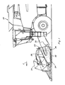
- a self-propelled combine 20 including a header 22 with a flexible cutterbar 24 configured for fore and aft movement, and a preload adjusting system 26 constructed and operable according to the teachings of the present invention.
- Cutterbar 24 is a conventionally constructed and operable sickle type cutter made of steel and including an elongate end-to-end array of knife sections reciprocatingly movable in a side-to-side direction relative to fixed cutter guards, for severing crops from a field as combine 20 is moved forwardly thereover, as denoted by arrow F.
- Header 22 additionally includes a conveyor arrangement 28 operable for gathering the cut crops, and conveying them to a center region of header 22, and into a feeder 30 of combine 20, in the well-known manner.
- conveyor arrangement 28 is of a helical auger style, but it should be recognized and understood that, alternatively, the conveyor arrangement could be configured as a draper type.
- preload adjusting system 26 is shown in association with a header of a combine, it should be recognized that it could be utilized with a header of a windrower or another plant cutting machine.
- Combine 20 is also of conventional construction and operation, for separating grain from the cut crops, collecting the grain, and discharging the material other than grain. For windrower applications, combine 20 would be replaced by a tractor.
- cutterbar 24 is illustrated configured in a float mode, such that portions of cutterbar 24 along the width (the side to side direction in relation to combine 20) are in effect supported all or in part by contact with a ground surface therebeneath, and such that the cutterbar will sever the crops at or just above the ground surface.
- This mode is typically used for harvesting crops such as soybeans and other legumes.
- cutterbar 24 allows a limited range of upward and downward movement of individual regions thereof, for conforming to contours of the ground surface, to maintain a generally uniform cutting height, and such that impacts and jarring that can result from contact with raised surface contours and irregularities, e.g., furrow ridges, clumps, rocks, and the like, are reduced.
- This flex capability may be provided in association with a header height control system (not shown) automatically operable for raising header 22 responsive to a certain extent of upward movement of cutterbar 24, and lowering the header responsive to a certain extent of downward movement, in the well-known manner.
- cutterbar 24 of header 22 is supported by support apparatus 32 disposed at spaced locations along the width thereof, for upward and downward movement, as illustrated by arrows A in Figures 3 and 5 , to facilitate the flexing thereof.
- a typical header 22 and cutterbar 24 may be as much as 12 m (40 feet) or more wide, and support apparatus 32 will provide sufficient flexibility to allow spaced apart regions of the cutterbar to be simultaneously located at different elevations, which may be required for providing desired ground contour following capabilities.
- cutterbar 24 and support apparatus 32 will have sufficient robustness so as to be capable of withstanding intermittent contacts and impacts with ground features, e.g., raised areas, furrow ridges, logs, rocks, etc., over the course of use.
- each of support apparatus 32 preferably comprises suitable structure, of steel or other suitable metal, here, a telescoping arm assembly (as best illustrated in Figure 2A ) including a forwardly located first arm 36 having a forwardmost end attached to and supporting cutterbar 24, extending telescopically from a rearwardly located second arm 38 pivotally connected to a structural element of header 22 at a more rearward location.
- a telescoping arm assembly as best illustrated in Figure 2A ) including a forwardly located first arm 36 having a forwardmost end attached to and supporting cutterbar 24, extending telescopically from a rearwardly located second arm 38 pivotally connected to a structural element of header 22 at a more rearward location.
- Each support apparatus 32 is disposed beneath or integrated with a pan or floor 40 of header 22, such that cutterbar 24 projects forwardly from a forwardmost edge 42 thereof.
- floor 40 is also preferably of telescoping construction, including a forward section 44 including forwardmost edge 42, suitably configured for flexure, such as by overlapping panels in connection with cutterbar 24 at locations along the width thereof, for upward, downward, forward, and rearward movement therewith relative to a rear section 46 located beneath conveyor arrangement 28.
- Second arm 38 of each support apparatus 32 is pivotally connected to a suitable structural element of header 22, e.g., rear section 46 of floor 40, preferably by a hinge or pinned pivot joint 48, to enable the upward and downward pivotal movement of cutterbar 24 and the associated portion or portions of forward section 44 of the floor.
- header 22 preferably incorporates a synchronization mechanism.
- a preferred mechanism comprises racks 50 on first arms 36, respectively, enmeshed with pinions 52 mounted on the associated second arms 38 or otherwise suitably connected to header 22, so as to be fixed relative to the fore and aft direction.
- Pinions 52 are fixedly mounted coaxially to a shaft which extends sidewardly along header 22, for joint rotation.
- racks 50 will move relative to pinions 52, to cause their uniform and simultaneous rotation.
- Pinions 52 can be coaxial with pivot joints 48 such that support apparatus 32 will pivot thereabout.
- the uniform fore and aft movements of cutterbar 24, forward section 44 of floor 40, and first arms 36, as well as the synchronized rotation of pinions 52, can be effected using any suitable driver or drivers 58, which can be, for instance, one or more fluid cylinders or other linear actuators connected between cutterbar 24 or one or more of first arms 36, and second arm 38, or a fore and aft fixed portion of header 22, such as rear section 46 of floor 40, as illustrated in Figures 2A and 6 , under control of a suitable input device, which can be, for example, a switch or touch screen located in the operator cabin of the combine (not shown).
- a suitable input device which can be, for example, a switch or touch screen located in the operator cabin of the combine (not shown).
- extension of drivers 58 will cause forward extension of the cutterbar 24, and retraction of drivers 58 will cause retraction of the cutterbar, although other configurations, e.g. linear actuators, could alternatively be used.
- pinions 52 will be rotated in unison by corresponding movements of the racks 50, such that the cutterbar is uniformly moved.
- a suitable position sensor 60 which can be, for example: a rotary sensor, such as a potentiometer, operable for sensing a rotational position of a pinion, or pinions 52 via a shaft ; a linear position sensor; a proximity sensor; optical sensor, or the like.
- system 26 includes a processor based controller 62 in connection with sensor 60 via a suitable communications path 64 such as a wiring harness, wired or wireless communications network, for receiving signals from sensor 60 representative of the fore and aft position of cutterbar 24.
- Controller 62 is also connected by a communications path 64 to an input device 66 usable by an operator to select and input commands, and to a biasing element for generating the preload force, which here comprises a pressurized fluid cylinder or cylinders 70 in connection with a fluid system 68.
- Fluid system 68 will include a fluid pump configured and operable in the well known manner for generating a supply of pressurized fluid and delivering the pressurized fluid to the one or more fluid cylinders 70, via fluid paths 72.
- One or more of fluid paths 72 can also include an accumulator 74 (two illustrated) to provide resilient yielding movement responsive to externally applied loads, e.g., contact between cutterbar 24 and raised ground surface features, obstacles, and the like, and return to the equilibrium or normal position when the cutterbar has passed that condition, while damping associated shock.
- Each fluid cylinder 70 comprising the biasing elements of system 26, as illustrated here is pivotally connected to, and extends between, the rear end of support apparatus 32 and a rear portion of floor 40 or other suitable structure of the header.
- Each fluid cylinder 70 is conventionally constructed and operable, including a piston end chamber 76 and a rod end chamber 78, connected to respective fluid paths 72, for receiving and holding fluid.
- cutterbar 24 it will typically be desired for cutterbar 24 to have a free state normal or equilibrium pivotal position about as shown in Figure 5 , so as to have some ability to pivot both up and down as required for following ground surface contours, and with the preload force constituting an upwardly directed force acting against cutterbar 24 to counterbalance at least a portion of the weight of the cutterbar and support apparatus 32 and thus the down force exerted thereby.
- the net effect is that when an upwardly extending ground surface contour or feature is encountered, less upward force will be required to raise cutterbar 24 over that contour or feature, and the dropping of the cutterbar after passage thereover will be less abrupt and forceful. This is advantageous as it reduces shock, vibration, and other stress on the header and related apparatus that could possibly cause damage, ground scalping and other problems.
- the amount of the preload force e.g., increase it, for decreasing down force, ground scalping, shock and other conditions, for instance, when harvesting from rougher sections of fields, uneven terrain, and any of a variety of other reasons.
- the distance from the cutterbar to pivot joint 48 will change, which will in turn change the net down force, and thus necessitate adjusting the preload force for maintaining a desired or set down force value.
- Preload adjusting system 26 is configured and operable for varying or changing the preload force responsive to commands inputted by an operator using input 66 for varying down force. Additionally, system 26 is configured to automatically operate to vary the preload force responsive to fore and aft movements of the cutterbar, to maintain the down force at the set value. This is effected under control of controller 62, by changing the fluid pressures in chambers 76 and 78 of fluid cylinders 70 and the respective associated lines 72 and accumulators 74. As noted above, forward extension of cutterbar 24 will increase net down force, and retraction will reduce it, both of which movements will be detected by sensor or sensors 60.
- system 26 will automatically compensate for or cancel such net increase in the down force by increasing fluid pressure in piston end chamber 76 and/or reducing pressure in rod end chamber 78; and will compensate for by a decrease by decreasing pressure in chamber 76 and/or increasing it in chamber 78.
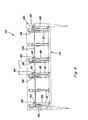
- FIGs 6 , 7 and 8 illustrate an alternative embodiment of a preload adjusting system 80 of the invention, shown in association with header 22, cutterbar 24 and support apparatus 32.
- System 80 utilizes elements of system 26, including biasing elements comprising fluid cylinders 70 in association with support elements 32.
- system 80 additionally includes the other above discussed aspects of fluid system 68, including controller 62, input device 66, accumulators 74, and connecting communication and fluid paths 64 and 72, to enable selecting and setting a down force in the above described manner.
- Drivers 58 are also used for extending and retracting the cutterbar as before.
- System 80 additionally includes adjustable biasing elements which comprise torsion springs 82 in connection with some or all of support apparatus 32, and apparatus 84 for mechanically automatically and uniformly varying the torsion in springs 82 with or proportional to the fore and aft movements of cutterbar 24, such that the springs 82 will exert a portion or component of the preload force, which component will be automatically varied with cutterbar fore and aft position for maintaining a set down force. This can be done while maintaining a constant preload force generated by cylinders 70 in the above described manner, or in conjunction or cooperation with variations in that force component.
- adjustable biasing elements comprise torsion springs 82 in connection with some or all of support apparatus 32, and apparatus 84 for mechanically automatically and uniformly varying the torsion in springs 82 with or proportional to the fore and aft movements of cutterbar 24, such that the springs 82 will exert a portion or component of the preload force, which component will be automatically varied with cutterbar fore and aft position for maintaining
- apparatus 84 comprises cables 86, which wind about reels 88 connected to torsion springs 82 by force multipliers 90, such that movements of cutterbar 24 in the fore direction will pull cables 86 so as to change the torsion in torsion springs 82 in a first manner, and movements of the cutterbar in the aft direction will change the torsion in another manner.
- illustrated force multipliers 90 comprise gearboxes, each having a first shaft 92 connected to and supporting a reel 88, and a second shaft 94 in connection with the associated spring 82, shafts 92 and 94 being connected together by a gear arrangement within the gearbox having a ratio whereby rotation of first shaft 92 will cause a lesser degree of rotation of second shaft 94.
- spring 82 One end of spring 82 is connected to first shaft 94 at connection 96 and the opposite end is connected to support apparatus 32 at connection 98, and the gear box is fixed to the underside of floor 40 of header 12 or other suitable fixed structure by a connection 100, such that unwinding or pulling of cable 86 about reel 88 as cutterbar 24 is extended forwardly will cooperatively rotate first shaft 92 in a manner for rotating second shaft 94 for increasing the torsion in spring 82, and thus that component of the preload force, and retraction of cutterbar 24 will allow spring 82 to cooperatively rotate second shaft 94 to in turn rotate first shaft 92 to a greater extent to wind or take up more of cable 86 about reel 88, to thereby reduce the torsion in the spring and thus that component of the preload force.
- the changes in torsion in spring 82 resulting from winding and unwinding it and the effect on the preload force generated thereby will correspond directly with the changes in fore and aft position of the cutterbar, such that the preload force exerted against support apparatus 32 will adjust to and offset the changes the down force resulting from the fore and aft movements of the cutterbar, such that there will be no, or only an inconsequential, net down force change.
- a pivot shaft 102 is shown extending between support apparatus 32 of header 22, for synchronizing the fore and aft movements thereof.
- Shaft 102 can be coaxial with apparatus such as pinions 52 of the respective apparatus 32, which, in turn, can be coaxial with shafts 92 and 94, or offset therefrom, as desired.
- the cable and gearbox type force multiplier, and torsion spring arrangement of system 80 represents just one of several spring type mechanisms that could be employed according to the invention for varying a spring force providing or counteracting a preload acting on a cutterbar corresponding with changes in the fore and aft position of the cutterbar, and that, as a result, the present invention is not intended to be limited to just the mechanism illustrated.
- a torque arm or arms could be connected between the telescoping arm or arms of support apparatus 32 or between first arm 36 and floor 40 or other fixed structure, and configured to decrease or increase spring torsion with and proportional to fore and aft cutterbar movements.
Landscapes
- Life Sciences & Earth Sciences (AREA)
- Environmental Sciences (AREA)
- Harvester Elements (AREA)
- Pretreatment Of Seeds And Plants (AREA)
Claims (15)
- Table de coupe (22) pour une machine agricole de coupe de plantes (20), comprenant :un plancher allongé (40),une pluralité de bras de support allongés (32) reliés de manière pivotante au plancher (40) ou à des éléments structurels reliés à celui-ci et supportant une barre de coupe flexible (24) pour un mouvement vers le haut et vers le bas (A) par rapport au plancher (40), les bras de support étant configurés pour avoir une longueur variable permettant de faire varier la position vers l'avant et l'arrière (B) de la barre de coupe par rapport au sol, etdes éléments de précontrainte (70/82) reliés respectivement entre le plancher (40) et au moins certains des bras de support (32), les éléments de précontrainte étant configurés et fonctionnels pour exercer de façon élastique, respectivement, une force de précontrainte contre les bras de support (32), pour presser la barre de coupe (24) vers le haut ou vers le bas,caractérisée en ce que la table de coupe (22) comprend en plus :un système de réglage de précontrainte (26/80) relié aux éléments de précontrainte (70/82) et à la barre de coupe (24) et configuré pour faire varier automatiquement la force de précontrainte exercée en fonction de la position avant-arrière (B) de la barre de coupe.
- Table de coupe selon la revendication 1, comprenant en plus un dispositif de détection (60) configuré et fonctionnel pour détecter la position avant-arrière (B) de la barre de coupe (24) et fournir des informations représentatives de celle-ci au système de réglage de précontrainte (26/80).
- Table de coupe selon la revendication 1 ou 2, caractérisée en ce qu'au moins un des bras de support (32) comprend un élément (36) portant une partie de la barre de coupe (24) et mobile dans une direction avant et arrière par rapport au plancher (40) pour modifier la position avant/arrière (B) de la partie de la barre de coupe, et en ce que le système de réglage de précontrainte (26/80) comprend un organe (52) relié à l'élément (36) ou à la barre de coupe, configuré pour se déplacer de manière correspondante aux mouvements vers l'avant et l'arrière (B) de la barre de coupe.
- Table de coupe selon la revendication 3, caractérisée en ce que l'élément (36) comprend une crémaillère (50) et l'organe comprend un pignon (52) engrené avec la crémaillère de telle sorte que le mouvement correspondant aux mouvements vers l'avant et l'arrière (B) comprendra un mouvement rotatif du pignon.
- Table de coupe selon la revendication 4, en dépendant de la revendication 2, caractérisée en ce que le pignon (52) est monté sur un arbre rotatif avec celui-ci autour d'un axe de rotation au travers de celui-ci et le dispositif de détection (60) est relié à l'arbre et configuré et fonctionnel pour détecter la rotation de l'arbre et fournir des informations représentatives de celle-ci au système de réglage de précontrainte (26/80).
- Table de coupe selon la revendication 5, caractérisée en ce que le dispositif de détection configuré et fonctionnel pour détecter la rotation de l'arbre comprend un potentiomètre (60).
- Table de coupe selon l'une quelconque des revendications précédentes, caractérisée en ce que les éléments de précontrainte comprennent au moins un vérin hydraulique (70) en liaison fluidique avec un accumulateur (74) et le système de réglage de précontrainte (26) est configuré pour faire varier automatiquement la pression dans le vérin hydraulique (70) et l'accumulateur (74) en fonction de la position avant et arrière (B) de la barre de coupe (24).
- Table de coupe selon la revendication 7, caractérisée en ce que le système de réglage de précontrainte (26) est relié en contrôle de fonctionnement d'un élément fonctionnel pour faire varier la pression dans le vérin hydraulique (70) afin de modifier la force de précontrainte.
- Table de coupe selon l'une quelconque des revendications précédentes, caractérisée en ce que les éléments de précontrainte réglables comprennent des ressorts de torsion (82) et le système de réglage de précontrainte (80) comprend des éléments (86) reliés à la barre de coupe (24) pour être en mouvement avec celle-ci dans les sens avant et arrière (B) de manière à modifier uniformément la torsion dans les ressorts, de façon correspondante aux mouvements avant et arrière de la barre de coupe, afin de faire varier la force de précontrainte.
- Table de coupe selon la revendication 9, caractérisée en ce que les éléments reliés à la barre de coupe (24) comprennent des câbles (86).
- Table de coupe selon la revendication 10, caractérisée en ce que les câbles (86) s'enroulent autour de bobines (88) reliées aux ressorts de torsion (82) par des multiplicateurs de force (90) de telle sorte que des mouvements de la barre de coupe (24) vers l'avant tireront les câbles de manière à modifier la torsion des ressorts de torsion (82) d'une première manière, et des mouvements vers l'arrière modifieront la torsion d'une autre manière.
- Table de coupe selon la revendication 11, caractérisée en ce que les multiplicateurs de force (90) comprennent des boîtes d'engrenage.
- Table de coupe selon l'une quelconque des revendications précédentes, caractérisée en ce que la pluralité de bras de support allongés (32) sont respectivement reliés de façon pivotante au plancher (40) par des articulations à pivot (48).
- Table de coupe selon l'une quelconque des revendications précédentes, caractérisée en ce que :les bras de support (32) ont des longueurs télescopiques permettant de faire varier la position avant/arrière (B) de la barre de coupe (24) par rapport au plancher (40), etla table de coupe comprend un dispositif (50, 52) s'étendant entre au moins certains des bras de support (32), configuré et fonctionnel pour contrôler les longueurs télescopiques de ceux-ci de façon sensiblement uniforme.
- Table de coupe selon la revendication 14, caractérisée en ce que le dispositif comprend des crémaillères (50) sur les bras de support (32), et des pignons (52) sur le plancher (40) s'étendant au travers des articulations à pivot (48) reliant de façon pivotante les bras de support au plancher, les pignons étant reliés ensemble pour une rotation de l'articulation.
Applications Claiming Priority (1)
| Application Number | Priority Date | Filing Date | Title |
|---|---|---|---|
| US12/754,754 US7992374B1 (en) | 2010-04-06 | 2010-04-06 | Agricultural plant cutting header with fore and aft adjustable flexible cutterbar having automatic preload adjustment |
Publications (3)
| Publication Number | Publication Date |
|---|---|
| EP2374344A2 EP2374344A2 (fr) | 2011-10-12 |
| EP2374344A3 EP2374344A3 (fr) | 2012-10-17 |
| EP2374344B1 true EP2374344B1 (fr) | 2014-10-01 |
Family
ID=44318453
Family Applications (1)
| Application Number | Title | Priority Date | Filing Date |
|---|---|---|---|
| EP11161183.6A Active EP2374344B1 (fr) | 2010-04-06 | 2011-04-05 | Tête de découpage d'installation agricole avec guide-chaîne flexible ajustable vers l'avant et l'arrière doté d'un réglage de préchargement automatique |
Country Status (2)
| Country | Link |
|---|---|
| US (1) | US7992374B1 (fr) |
| EP (1) | EP2374344B1 (fr) |
Families Citing this family (27)
| Publication number | Priority date | Publication date | Assignee | Title |
|---|---|---|---|---|
| CA2766611A1 (fr) * | 2011-01-28 | 2012-07-28 | Macdon Industries Ltd. | Bec cueilleur pour cultures a haute teneur en biomasse |
| US8484939B1 (en) * | 2012-08-31 | 2013-07-16 | Macdon Industries Ltd. | Draper seal for crop harvesting header |
| BE1021999B1 (nl) * | 2014-07-11 | 2016-02-03 | Cnh Industrial Belgium Nv | Maaier |
| BE1022840B1 (nl) | 2015-03-09 | 2016-09-20 | Cnh Industrial Belgium Nv | Maaier voor een oogstmachine die een verplaatsbare maaibalktafel bevat |
| US10236718B2 (en) | 2015-10-16 | 2019-03-19 | Cnh Industrial America Llc | Wireless harvesting header connection |
| US10034428B2 (en) * | 2016-10-05 | 2018-07-31 | Cnh Industrial America Llc | Agricultural header with cutter tracking reel |
| CA3081598C (fr) * | 2016-11-24 | 2022-09-06 | Macdon Industries Ltd. | Organe de coupe a sections multiples avec lame de coupe de recolte souple |
| US10349578B2 (en) * | 2017-02-16 | 2019-07-16 | Cnh Industrial America Llc | Combination flex and rigid header height control in a harvester |
| US10582660B2 (en) | 2017-10-04 | 2020-03-10 | Deere & Company | Agricultural harvesting head with float arm pivots below reciprocating knives |
| WO2020101841A1 (fr) * | 2018-11-16 | 2020-05-22 | Cnh Industrial America Llc | Mécanisme de verrouillage pour table de coupe agricole |
| AT522856B1 (de) * | 2019-06-27 | 2023-02-15 | Franz Schrattenecker | Schneidwerk für einen Mähdrescher |
| DE102019125279A1 (de) * | 2019-09-19 | 2021-03-25 | Carl Geringhoff Gmbh & Co. Kg | Schneidwerk mit längsbeweglichem Abstützelement zur Abstützung einer Förderfläche |
| DE102019125277A1 (de) * | 2019-09-19 | 2021-03-25 | Carl Geringhoff Gmbh & Co. Kg | Schneidwerk mit Blattfederpaket als Schneidelementträger |
| US11483971B2 (en) | 2019-10-18 | 2022-11-01 | Cnh Industrial America Llc | Cutter bar support linkage |
| US11406058B2 (en) | 2019-10-25 | 2022-08-09 | Cnh Industrial America Llc | Cutter bar support linkage |
| US11234368B2 (en) * | 2019-12-23 | 2022-02-01 | Cnh Industrial America Llc | Cutter bar assembly for a harvester |
| US11617300B2 (en) * | 2019-12-23 | 2023-04-04 | Cnh Industrial America Llc | Locking mechanism for an agricultural header |
| US11375658B2 (en) * | 2019-12-23 | 2022-07-05 | Cnh Industrial America Llc | System and method for leveling a cutter bar of a harvester |
| US11974516B2 (en) * | 2019-12-23 | 2024-05-07 | Cnh Industrial America Llc | Support system for an agricultural header |
| US11234367B2 (en) | 2019-12-23 | 2022-02-01 | Cnh Industrial America Llc | Systems and methods for adjusting a flexible cutter bar assembly |
| US11778943B2 (en) * | 2020-05-29 | 2023-10-10 | Deere & Company | Lockout system for header |
| US11559000B2 (en) * | 2020-05-29 | 2023-01-24 | Deere & Company | Lockout system for header |
| US12396393B2 (en) | 2021-07-20 | 2025-08-26 | Deer & Company | Automated lockout system for header |
| US12402561B2 (en) | 2021-07-20 | 2025-09-02 | Deere & Company | Automated lockout system for header |
| US12396387B2 (en) | 2021-07-20 | 2025-08-26 | Deere & Company | Automated lockout system for header |
| US12575497B2 (en) | 2021-09-08 | 2026-03-17 | Deere & Company | Automated lockout system for header |
| AT527147B1 (de) * | 2023-09-22 | 2024-11-15 | Franz Schrattenecker Ing | Schneidwerk für einen Mähdrescher |
Family Cites Families (27)
| Publication number | Priority date | Publication date | Assignee | Title |
|---|---|---|---|---|
| US4011709A (en) * | 1974-11-13 | 1977-03-15 | Deere & Company | Harvesting platform |
| US3982383A (en) | 1974-11-13 | 1976-09-28 | Deere & Company | Harvesting platform with a floating cutter bar |
| CA1079984A (fr) * | 1977-02-07 | 1980-06-24 | Graeme R. Quick | Moissonneuse |
| US4191006A (en) | 1978-05-08 | 1980-03-04 | International Harvester Company | Floating cutterbar knife drive |
| US4227363A (en) | 1978-09-01 | 1980-10-14 | International Harvester Company | Floating cutterbar header and height control |
| US4206583A (en) | 1978-09-01 | 1980-06-10 | International Harvester Company | Cutterbar floatation system |
| US4206584A (en) * | 1978-09-01 | 1980-06-10 | International Harvester Company | Floating cutterbar header |
| US4473993A (en) * | 1983-05-26 | 1984-10-02 | Sperry Corporation | Cutting angle adjustment mechanism for crop harvesting machines |
| US4441307A (en) * | 1983-08-30 | 1984-04-10 | Allis-Chalmers Corporation | Harvester header with floating cutter bar |
| US4573308A (en) * | 1984-04-02 | 1986-03-04 | Deere & Company | Harvesting platform with a floating cutterbar |
| DE3441209A1 (de) * | 1984-11-10 | 1986-05-15 | Claas Ohg, 4834 Harsewinkel | Schneidwerksmulde fuer erntemaschinen mit flexiblem schneidwerk |
| US4599852A (en) * | 1985-07-24 | 1986-07-15 | J. I. Case Company | Adjustable leaf spring suspension for flexible cutterbar |
| US5359836A (en) | 1993-02-01 | 1994-11-01 | Control Concepts, Inc. | Agricultural harvester with closed loop header control |
| US5327709A (en) | 1993-03-12 | 1994-07-12 | Ford New Holland, Inc. | Adjustable header flotation mechanism |
| DE19623754A1 (de) | 1996-06-14 | 1997-12-18 | Claas Ohg | Erntemaschine mit einem in seiner Arbeitslage gegenüber dem Boden höhenverstellbaren Vorsatzbearbeitungsgerät |
| US6029429A (en) | 1997-02-27 | 2000-02-29 | Macdon Industries Ltd. | Header for a crop harvesting machine with adjustment of a longitudinal shape of the cutter bar |
| US6041583A (en) | 1998-11-16 | 2000-03-28 | Deere & Company | Height sensing system for a harvester head |
| US6615570B2 (en) | 2001-06-28 | 2003-09-09 | Deere & Company | Header position control with forward contour prediction |
| DE10133105A1 (de) * | 2001-07-12 | 2003-02-06 | Claas Selbstfahr Erntemasch | Schneidwerk für Erntemaschinen |
| US20070193243A1 (en) * | 2006-02-10 | 2007-08-23 | Schmidt James R | Combine Harvester Draper Header Having Flexible Cutterbar |
| US7520115B2 (en) * | 2006-09-15 | 2009-04-21 | Deere & Company | Header float arm load compensation |
| US20090107094A1 (en) * | 2007-10-29 | 2009-04-30 | Bich Gary L | Automatic control system for a header of an agricultural harvesting machine and method of operation of the same |
| US20090277145A1 (en) * | 2008-05-09 | 2009-11-12 | Agco Corporation | Header height control system with multiple potentiometer input |
| US20090277148A1 (en) * | 2008-05-09 | 2009-11-12 | Agco Corporation | Flexible draper and cutter bar having shiftable crop divider with deflector |
| EP2315514B1 (fr) * | 2008-05-09 | 2012-04-25 | Agco Corporation | Plage de déplacement de barre de coupe réglable pour organe de coupe à barre de coupe souple |
| EP2147589B1 (fr) * | 2008-07-22 | 2012-06-27 | CNH Belgium N.V. | Entraînement de courroie pour tête d'abattage-ébranchage avec guide-chaîne mobile |
| US20100083629A1 (en) * | 2008-10-07 | 2010-04-08 | Klotzbach Karl W | Flexible cutterbar support apparatus with integral adjustable torsional preload mechanism and vibration damper |
-
2010
- 2010-04-06 US US12/754,754 patent/US7992374B1/en not_active Expired - Fee Related
-
2011
- 2011-04-05 EP EP11161183.6A patent/EP2374344B1/fr active Active
Also Published As
| Publication number | Publication date |
|---|---|
| US7992374B1 (en) | 2011-08-09 |
| EP2374344A3 (fr) | 2012-10-17 |
| EP2374344A2 (fr) | 2011-10-12 |
Similar Documents
| Publication | Publication Date | Title |
|---|---|---|
| US7992374B1 (en) | Agricultural plant cutting header with fore and aft adjustable flexible cutterbar having automatic preload adjustment | |
| EP3469876B1 (fr) | Système pour le flottement d'une aile sur une moissonneuse-batteuse a tablier | |
| US11778946B2 (en) | Flexible header with sectional height adjustment | |
| EP2285206B1 (fr) | Convoyeur à toile et barre de coupe souples avec bras pivotant pour entraînement de barre de coupe | |
| EP2896282B1 (fr) | Système de commande de hauteur de tête pour moissonneuse-batteuse | |
| EP2306801B1 (fr) | Tête de tablier dotée d une barre de coupe flexible comprenant une section centrale rigide | |
| US8534037B2 (en) | Flexible cutterbar stop structure for draper header | |
| EP3122169B1 (fr) | Régulation de la hauteur et de l'angle de coupe d'un tablier de coupe de moissonneuse-batteuse | |
| EP2315514B1 (fr) | Plage de déplacement de barre de coupe réglable pour organe de coupe à barre de coupe souple | |
| US7520115B2 (en) | Header float arm load compensation | |
| US20100083629A1 (en) | Flexible cutterbar support apparatus with integral adjustable torsional preload mechanism and vibration damper | |
| EP2288250B1 (fr) | Système de commande de hauteur de tête de moissonneuse à multiples entrées de potentiomètre | |
| US6523333B2 (en) | Sensor arm for combine header | |
| EP3878266B1 (fr) | Positionnement de diviseur de hauteur pour une moissonneuse agricole | |
| EA028084B1 (ru) | Машина для уборки урожая с калибровкой плавающих пружин жатки | |
| AU2018334164B2 (en) | Flex arm air bag linkage | |
| US12622355B2 (en) | Harvester machine having at least one height elastic lateral frame | |
| US12520761B2 (en) | Cutting unit having movable sidewalls |
Legal Events
| Date | Code | Title | Description |
|---|---|---|---|
| PUAI | Public reference made under article 153(3) epc to a published international application that has entered the european phase |
Free format text: ORIGINAL CODE: 0009012 |
|
| AK | Designated contracting states |
Kind code of ref document: A2 Designated state(s): AL AT BE BG CH CY CZ DE DK EE ES FI FR GB GR HR HU IE IS IT LI LT LU LV MC MK MT NL NO PL PT RO RS SE SI SK SM TR |
|
| AX | Request for extension of the european patent |
Extension state: BA ME |
|
| PUAL | Search report despatched |
Free format text: ORIGINAL CODE: 0009013 |
|
| AK | Designated contracting states |
Kind code of ref document: A3 Designated state(s): AL AT BE BG CH CY CZ DE DK EE ES FI FR GB GR HR HU IE IS IT LI LT LU LV MC MK MT NL NO PL PT RO RS SE SI SK SM TR |
|
| AX | Request for extension of the european patent |
Extension state: BA ME |
|
| RIC1 | Information provided on ipc code assigned before grant |
Ipc: A01D 41/14 20060101AFI20120907BHEP |
|
| 17P | Request for examination filed |
Effective date: 20130417 |
|
| RAP1 | Party data changed (applicant data changed or rights of an application transferred) |
Owner name: CNH INDUSTRIAL BELGIUM NV |
|
| GRAP | Despatch of communication of intention to grant a patent |
Free format text: ORIGINAL CODE: EPIDOSNIGR1 |
|
| INTG | Intention to grant announced |
Effective date: 20140430 |
|
| RIN1 | Information on inventor provided before grant (corrected) |
Inventor name: KLOTZBACH, KARL, W. Inventor name: BICH, GARY, L. Inventor name: RAYFIELD, JAMES, F. |
|
| GRAS | Grant fee paid |
Free format text: ORIGINAL CODE: EPIDOSNIGR3 |
|
| GRAA | (expected) grant |
Free format text: ORIGINAL CODE: 0009210 |
|
| AK | Designated contracting states |
Kind code of ref document: B1 Designated state(s): AL AT BE BG CH CY CZ DE DK EE ES FI FR GB GR HR HU IE IS IT LI LT LU LV MC MK MT NL NO PL PT RO RS SE SI SK SM TR |
|
| REG | Reference to a national code |
Ref country code: GB Ref legal event code: FG4D |
|
| REG | Reference to a national code |
Ref country code: AT Ref legal event code: REF Ref document number: 689072 Country of ref document: AT Kind code of ref document: T Effective date: 20141015 Ref country code: CH Ref legal event code: EP |
|
| REG | Reference to a national code |
Ref country code: IE Ref legal event code: FG4D |
|
| REG | Reference to a national code |
Ref country code: DE Ref legal event code: R096 Ref document number: 602011010207 Country of ref document: DE Effective date: 20141113 |
|
| REG | Reference to a national code |
Ref country code: NL Ref legal event code: VDEP Effective date: 20141001 |
|
| REG | Reference to a national code |
Ref country code: AT Ref legal event code: MK05 Ref document number: 689072 Country of ref document: AT Kind code of ref document: T Effective date: 20141001 |
|
| REG | Reference to a national code |
Ref country code: LT Ref legal event code: MG4D |
|
| PG25 | Lapsed in a contracting state [announced via postgrant information from national office to epo] |
Ref country code: NL Free format text: LAPSE BECAUSE OF FAILURE TO SUBMIT A TRANSLATION OF THE DESCRIPTION OR TO PAY THE FEE WITHIN THE PRESCRIBED TIME-LIMIT Effective date: 20141001 |
|
| PG25 | Lapsed in a contracting state [announced via postgrant information from national office to epo] |
Ref country code: IS Free format text: LAPSE BECAUSE OF FAILURE TO SUBMIT A TRANSLATION OF THE DESCRIPTION OR TO PAY THE FEE WITHIN THE PRESCRIBED TIME-LIMIT Effective date: 20150201 Ref country code: PT Free format text: LAPSE BECAUSE OF FAILURE TO SUBMIT A TRANSLATION OF THE DESCRIPTION OR TO PAY THE FEE WITHIN THE PRESCRIBED TIME-LIMIT Effective date: 20150202 Ref country code: ES Free format text: LAPSE BECAUSE OF FAILURE TO SUBMIT A TRANSLATION OF THE DESCRIPTION OR TO PAY THE FEE WITHIN THE PRESCRIBED TIME-LIMIT Effective date: 20141001 Ref country code: NO Free format text: LAPSE BECAUSE OF FAILURE TO SUBMIT A TRANSLATION OF THE DESCRIPTION OR TO PAY THE FEE WITHIN THE PRESCRIBED TIME-LIMIT Effective date: 20150101 Ref country code: FI Free format text: LAPSE BECAUSE OF FAILURE TO SUBMIT A TRANSLATION OF THE DESCRIPTION OR TO PAY THE FEE WITHIN THE PRESCRIBED TIME-LIMIT Effective date: 20141001 Ref country code: CZ Free format text: LAPSE BECAUSE OF FAILURE TO SUBMIT A TRANSLATION OF THE DESCRIPTION OR TO PAY THE FEE WITHIN THE PRESCRIBED TIME-LIMIT Effective date: 20141001 Ref country code: LT Free format text: LAPSE BECAUSE OF FAILURE TO SUBMIT A TRANSLATION OF THE DESCRIPTION OR TO PAY THE FEE WITHIN THE PRESCRIBED TIME-LIMIT Effective date: 20141001 |
|
| PG25 | Lapsed in a contracting state [announced via postgrant information from national office to epo] |
Ref country code: LV Free format text: LAPSE BECAUSE OF FAILURE TO SUBMIT A TRANSLATION OF THE DESCRIPTION OR TO PAY THE FEE WITHIN THE PRESCRIBED TIME-LIMIT Effective date: 20141001 Ref country code: HR Free format text: LAPSE BECAUSE OF FAILURE TO SUBMIT A TRANSLATION OF THE DESCRIPTION OR TO PAY THE FEE WITHIN THE PRESCRIBED TIME-LIMIT Effective date: 20141001 Ref country code: SE Free format text: LAPSE BECAUSE OF FAILURE TO SUBMIT A TRANSLATION OF THE DESCRIPTION OR TO PAY THE FEE WITHIN THE PRESCRIBED TIME-LIMIT Effective date: 20141001 Ref country code: AT Free format text: LAPSE BECAUSE OF FAILURE TO SUBMIT A TRANSLATION OF THE DESCRIPTION OR TO PAY THE FEE WITHIN THE PRESCRIBED TIME-LIMIT Effective date: 20141001 Ref country code: RS Free format text: LAPSE BECAUSE OF FAILURE TO SUBMIT A TRANSLATION OF THE DESCRIPTION OR TO PAY THE FEE WITHIN THE PRESCRIBED TIME-LIMIT Effective date: 20141001 Ref country code: CY Free format text: LAPSE BECAUSE OF FAILURE TO SUBMIT A TRANSLATION OF THE DESCRIPTION OR TO PAY THE FEE WITHIN THE PRESCRIBED TIME-LIMIT Effective date: 20141001 Ref country code: PL Free format text: LAPSE BECAUSE OF FAILURE TO SUBMIT A TRANSLATION OF THE DESCRIPTION OR TO PAY THE FEE WITHIN THE PRESCRIBED TIME-LIMIT Effective date: 20141001 Ref country code: GR Free format text: LAPSE BECAUSE OF FAILURE TO SUBMIT A TRANSLATION OF THE DESCRIPTION OR TO PAY THE FEE WITHIN THE PRESCRIBED TIME-LIMIT Effective date: 20150102 |
|
| REG | Reference to a national code |
Ref country code: DE Ref legal event code: R097 Ref document number: 602011010207 Country of ref document: DE |
|
| PG25 | Lapsed in a contracting state [announced via postgrant information from national office to epo] |
Ref country code: RO Free format text: LAPSE BECAUSE OF FAILURE TO SUBMIT A TRANSLATION OF THE DESCRIPTION OR TO PAY THE FEE WITHIN THE PRESCRIBED TIME-LIMIT Effective date: 20141001 Ref country code: SK Free format text: LAPSE BECAUSE OF FAILURE TO SUBMIT A TRANSLATION OF THE DESCRIPTION OR TO PAY THE FEE WITHIN THE PRESCRIBED TIME-LIMIT Effective date: 20141001 Ref country code: DK Free format text: LAPSE BECAUSE OF FAILURE TO SUBMIT A TRANSLATION OF THE DESCRIPTION OR TO PAY THE FEE WITHIN THE PRESCRIBED TIME-LIMIT Effective date: 20141001 Ref country code: EE Free format text: LAPSE BECAUSE OF FAILURE TO SUBMIT A TRANSLATION OF THE DESCRIPTION OR TO PAY THE FEE WITHIN THE PRESCRIBED TIME-LIMIT Effective date: 20141001 |
|
| PLBE | No opposition filed within time limit |
Free format text: ORIGINAL CODE: 0009261 |
|
| STAA | Information on the status of an ep patent application or granted ep patent |
Free format text: STATUS: NO OPPOSITION FILED WITHIN TIME LIMIT |
|
| 26N | No opposition filed |
Effective date: 20150702 |
|
| PG25 | Lapsed in a contracting state [announced via postgrant information from national office to epo] |
Ref country code: MC Free format text: LAPSE BECAUSE OF FAILURE TO SUBMIT A TRANSLATION OF THE DESCRIPTION OR TO PAY THE FEE WITHIN THE PRESCRIBED TIME-LIMIT Effective date: 20141001 Ref country code: LU Free format text: LAPSE BECAUSE OF FAILURE TO SUBMIT A TRANSLATION OF THE DESCRIPTION OR TO PAY THE FEE WITHIN THE PRESCRIBED TIME-LIMIT Effective date: 20150405 |
|
| REG | Reference to a national code |
Ref country code: CH Ref legal event code: PL |
|
| REG | Reference to a national code |
Ref country code: IE Ref legal event code: MM4A |
|
| PG25 | Lapsed in a contracting state [announced via postgrant information from national office to epo] |
Ref country code: LI Free format text: LAPSE BECAUSE OF NON-PAYMENT OF DUE FEES Effective date: 20150430 Ref country code: CH Free format text: LAPSE BECAUSE OF NON-PAYMENT OF DUE FEES Effective date: 20150430 |
|
| PG25 | Lapsed in a contracting state [announced via postgrant information from national office to epo] |
Ref country code: SI Free format text: LAPSE BECAUSE OF FAILURE TO SUBMIT A TRANSLATION OF THE DESCRIPTION OR TO PAY THE FEE WITHIN THE PRESCRIBED TIME-LIMIT Effective date: 20141001 |
|
| REG | Reference to a national code |
Ref country code: FR Ref legal event code: PLFP Year of fee payment: 6 |
|
| PG25 | Lapsed in a contracting state [announced via postgrant information from national office to epo] |
Ref country code: IE Free format text: LAPSE BECAUSE OF NON-PAYMENT OF DUE FEES Effective date: 20150405 |
|
| PG25 | Lapsed in a contracting state [announced via postgrant information from national office to epo] |
Ref country code: MT Free format text: LAPSE BECAUSE OF FAILURE TO SUBMIT A TRANSLATION OF THE DESCRIPTION OR TO PAY THE FEE WITHIN THE PRESCRIBED TIME-LIMIT Effective date: 20141001 |
|
| REG | Reference to a national code |
Ref country code: FR Ref legal event code: PLFP Year of fee payment: 7 |
|
| PG25 | Lapsed in a contracting state [announced via postgrant information from national office to epo] |
Ref country code: SM Free format text: LAPSE BECAUSE OF FAILURE TO SUBMIT A TRANSLATION OF THE DESCRIPTION OR TO PAY THE FEE WITHIN THE PRESCRIBED TIME-LIMIT Effective date: 20141001 Ref country code: BG Free format text: LAPSE BECAUSE OF FAILURE TO SUBMIT A TRANSLATION OF THE DESCRIPTION OR TO PAY THE FEE WITHIN THE PRESCRIBED TIME-LIMIT Effective date: 20141001 Ref country code: HU Free format text: LAPSE BECAUSE OF FAILURE TO SUBMIT A TRANSLATION OF THE DESCRIPTION OR TO PAY THE FEE WITHIN THE PRESCRIBED TIME-LIMIT; INVALID AB INITIO Effective date: 20110405 |
|
| PG25 | Lapsed in a contracting state [announced via postgrant information from national office to epo] |
Ref country code: TR Free format text: LAPSE BECAUSE OF FAILURE TO SUBMIT A TRANSLATION OF THE DESCRIPTION OR TO PAY THE FEE WITHIN THE PRESCRIBED TIME-LIMIT Effective date: 20141001 |
|
| PG25 | Lapsed in a contracting state [announced via postgrant information from national office to epo] |
Ref country code: BE Free format text: LAPSE BECAUSE OF FAILURE TO SUBMIT A TRANSLATION OF THE DESCRIPTION OR TO PAY THE FEE WITHIN THE PRESCRIBED TIME-LIMIT Effective date: 20141001 |
|
| REG | Reference to a national code |
Ref country code: FR Ref legal event code: PLFP Year of fee payment: 8 |
|
| PG25 | Lapsed in a contracting state [announced via postgrant information from national office to epo] |
Ref country code: MK Free format text: LAPSE BECAUSE OF FAILURE TO SUBMIT A TRANSLATION OF THE DESCRIPTION OR TO PAY THE FEE WITHIN THE PRESCRIBED TIME-LIMIT Effective date: 20141001 |
|
| PG25 | Lapsed in a contracting state [announced via postgrant information from national office to epo] |
Ref country code: AL Free format text: LAPSE BECAUSE OF FAILURE TO SUBMIT A TRANSLATION OF THE DESCRIPTION OR TO PAY THE FEE WITHIN THE PRESCRIBED TIME-LIMIT Effective date: 20141001 |
|
| REG | Reference to a national code |
Ref country code: DE Ref legal event code: R082 Ref document number: 602011010207 Country of ref document: DE Representative=s name: MEISSNER BOLTE PATENTANWAELTE RECHTSANWAELTE P, DE |
|
| PGFP | Annual fee paid to national office [announced via postgrant information from national office to epo] |
Ref country code: GB Payment date: 20230420 Year of fee payment: 13 |
|
| GBPC | Gb: european patent ceased through non-payment of renewal fee |
Effective date: 20240405 |
|
| PG25 | Lapsed in a contracting state [announced via postgrant information from national office to epo] |
Ref country code: GB Free format text: LAPSE BECAUSE OF NON-PAYMENT OF DUE FEES Effective date: 20240405 |
|
| PG25 | Lapsed in a contracting state [announced via postgrant information from national office to epo] |
Ref country code: GB Free format text: LAPSE BECAUSE OF NON-PAYMENT OF DUE FEES Effective date: 20240405 |
|
| PGFP | Annual fee paid to national office [announced via postgrant information from national office to epo] |
Ref country code: DE Payment date: 20250428 Year of fee payment: 15 |
|
| PGFP | Annual fee paid to national office [announced via postgrant information from national office to epo] |
Ref country code: IT Payment date: 20250422 Year of fee payment: 15 |
|
| PGFP | Annual fee paid to national office [announced via postgrant information from national office to epo] |
Ref country code: FR Payment date: 20250424 Year of fee payment: 15 |