EP2374385B1 - Infrarot-Kochgerät - Google Patents
Infrarot-Kochgerät Download PDFInfo
- Publication number
- EP2374385B1 EP2374385B1 EP11153436.8A EP11153436A EP2374385B1 EP 2374385 B1 EP2374385 B1 EP 2374385B1 EP 11153436 A EP11153436 A EP 11153436A EP 2374385 B1 EP2374385 B1 EP 2374385B1
- Authority
- EP
- European Patent Office
- Prior art keywords
- cooking
- lateral
- cartridge
- cooking appliance
- appliance
- Prior art date
- Legal status (The legal status is an assumption and is not a legal conclusion. Google has not performed a legal analysis and makes no representation as to the accuracy of the status listed.)
- Active
Links
Images


Classifications
-
- A—HUMAN NECESSITIES
- A47—FURNITURE; DOMESTIC ARTICLES OR APPLIANCES; COFFEE MILLS; SPICE MILLS; SUCTION CLEANERS IN GENERAL
- A47J—KITCHEN EQUIPMENT; COFFEE MILLS; SPICE MILLS; APPARATUS FOR MAKING BEVERAGES
- A47J37/00—Baking; Roasting; Grilling; Frying
- A47J37/06—Roasters; Grills; Sandwich grills
- A47J37/067—Horizontally disposed broiling griddles
- A47J37/0676—Horizontally disposed broiling griddles electrically heated
-
- F—MECHANICAL ENGINEERING; LIGHTING; HEATING; WEAPONS; BLASTING
- F24—HEATING; RANGES; VENTILATING
- F24C—DOMESTIC STOVES OR RANGES ; DETAILS OF DOMESTIC STOVES OR RANGES, OF GENERAL APPLICATION
- F24C1/00—Stoves or ranges in which the fuel or energy supply is not restricted to solid fuel or to a type covered by a single one of the following groups F24C3/00 - F24C9/00; Stoves or ranges in which the type of fuel or energy supply is not specified
- F24C1/14—Radiation heating stoves and ranges, with additional provision for convection heating
Definitions
- the present invention relates to an infrared cooking appliance.
- the principle of this type of cooking is to cook food thanks to the infrared radiation mastered and steam; infrared radiation can cook food at a temperature below 95 ° C. This low temperature cooking does not degrade foods.
- An apparatus for infra-red cooking includes a metal structure that supports one or two infrared radiation emission cassettes, above which is placed a glass container permeable to infrared radiation and in which steam is developed. .
- Each infrared radiation emission cassette has several tubes that emit a radiation of between 6 and 14 ⁇ m.
- an infrared radiation emission cassette generates a significant heat which, at the level of the actual structure of the apparatus, can cause problems.
- This type of apparatus is generally provided with reflecting surfaces which direct the flow towards the center of the apparatus where a glass container is located. Nevertheless, it inevitably occurs a heating of the outer walls of the device which is not desirable for the user of the device and its environment.
- the present invention aims to remedy all or part of the various disadvantages mentioned above.
- an object of the present invention is in particular to provide an infrared cooking appliance allowing better management of the heat released by the radiating elements while having a simple structure to manufacture and to isolate and while remaining compact.
- the cooking apparatus according to the present invention makes it possible to evacuate the heat caused by the presence of the cooking cassettes in an efficient manner thanks to the differential speed and temperature of the central and lateral flows.
- the lateral channels behave like a nozzle and contribute, by the speed differential between the central and lateral flows, to the extraction of the upper and lower central flows.
- the cooking appliance according to the invention is, moreover, simple to produce and the manufacturing and thermal insulation costs remain moderate compared to an appliance. cooking according to the prior art.
- the cooking apparatus according to the present invention also makes it possible to maintain the surface elements of the cooking appliance at an acceptable temperature during its operation and this by a Vogellic management of the heat removal. An acceptable temperature of the components of the cooking appliance during its operation can also reduce the risk of burns for the user.
- the cooking appliance comprises two reflectors which at least partially seal each of the side faces of the cooking space. This arrangement has very positive consequences on the operation of the device because it limits the energy consumption of the device avoiding energy losses and it allows to homogenize cooking. In the absence of these reflectors, the side cooking is less than the central cooking in the cooking recipeint.
- the cooking apparatus comprises a generally C-shaped carcass comprising a rear wall and two upper and lower plates.
- the carcass thus defined may for example be manufactured from a folded sheet.
- the upper plate may have two side flaps and the lower plate may have two side flaps, which has the advantage of stiffening the carcass and, therefore, the device itself but also allows to create a wall for for example, guiding bundles of cables that feed the cooking cassettes.
- This arrangement also makes it possible to mechanically protect these cables against, for example, an intrusion coming from the openings.
- these flaps delimit a static air gap which is adjacent to the cooking cassette. In other words, this arrangement makes it possible to create a double degree of insulation with a static air space directly adjacent to the cooking cassette and a dynamic air flow, particularly in the lateral direction.
- each of the cooking cassettes is encapsulated by an insulating sheet, which allows to create a static envelope around the heating tubes that form the cooking cassettes.
- the upper plate and the lower plate of the carcass each have a recess in which is inserted a cooking cassette.
- the upper cooking cassette can be protected by a grid of protection and the lower cassette can be protected by a ceramic hob.
- each fitting has a general shape of C having a vertical flange which abuts against the rear wall and two superposed horizontal branches which abut against the upper and lower plates.
- the frame of the furnace is thus completed by two fittings that can be obtained by cutting processes (laser or other) or inexpensive injection and well suited to mass production. These two fittings with the carcass are thus the base of the apparatus according to the invention.
- This arrangement makes it possible to have two small fans.
- the vertical wing of at least one fitting has a double inflection so that the upper side channels have a section that is unequal to that of the lower side channels.
- This arrangement allows, on the one hand, to impart greater rigidity to the fitting and also makes it possible to create side channels of unequal sections in their upper and lower components. This arrangement also makes it possible to distribute the air flows as well as possible by acting on the pressure drops.
- the lower cooking cassette has a surface that exceeds that of the upper cassette.
- This arrangement allows a more homogeneous cooking by optimizing the radiation surfaces.
- the casseroles that are intended to be placed in the oven have substantially trapezoidal shapes. This arrangement therefore makes it possible to adapt the radiating surface to the shape of the cups which are flared downwards, where the most important surface of radiation is thus located.
- the apparatus has two C-shaped side cheeks having at their two lateral ends openings through which the cooling flow is extracted.
- the cheeks act in synergy with the fittings to give the device its rigidity. This point is important because the upper cooking cassette is cantilevered; the fittings and the cheeks which may be simple cut sheets confer by their combined actions the necessary rigidity.
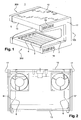
- the cooking appliance 1 of the figure 1 has a general shape in C with a rear portion 100 and two horizontal portions superimposed upper 200 and lower 300 defining a blank space. It is in this space that a glass container is slipped into which steam is formed which cooks food at less than 100 ° C.
- the cooking appliance 1 is part of a parallelepiped open on three sides.
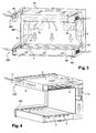
- the cooking appliance 1 as represented for example in Figure 3 and 4 , comprises two cooking cassettes 2, 3 arranged facing one another.
- Each cooking cassette 2, 3 has a plurality of infrared radiators 4 which emit infrared radiation directed to a cooking space 5 defined between the cooking cassettes 2,3.
- the infrared radiating elements 4 are preferably protected by a vitroceramic glass pane in the lower part or by a metal grid in the upper part.
- the cooking space 5 is delimited laterally by two reflectors 7 as can be seen at figure 1 which at least partially block the lateral faces
- the cooking apparatus comprises a carcass 9 in the general shape of C.
- This carcass 9 can be, as shown in FIG. figure 8 , made by folding from a single piece of sheet metal which is therefore of a cost of manufacture and reduced assembly.
- the carcass 9 which defines the cooking space may comprise a bottom wall 91 and two upper plates 92 and lower 93.
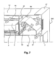
- the upper plate 92 (cf. figure 7 ) is provided with two side flaps 94; in a similar way, the lower plate 93 (cf. figure 6 ) which is also provided with two side flaps 95.
- the lower plate 93 further has a front flap 96.
- each of the upper plates 92 and lower 93 has a recess in which are inserted respectively an upper cooking cassette 3 and a lower cooking cassette 2.
- Each cooking cassette 2 and 3 is encapsulated in a sheet of insulation vertically and horizontally; this encapsulation is also effective laterally thanks on the one hand to the fittings 6 and on the other hand to the flaps 94 of the upper plate 92 and the flaps 95 of the bottom plate 93.
- each cooking cassette 2 and 3 and more particularly the radiating elements 4 which compose the cooking cassettes 2 and 3 is surrounded by a static air envelope which is conventionally shown with hatching on the figure 6 , 7 and 9 . It should be noted that this air envelope also extends on the lateral faces of the cooking cassettes.
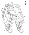
- the cooking apparatus further comprises two fittings 6, for example, generally C-shaped metal sheet which in this case are identical.
- Each of these brackets 6 has a vertical wing 61 and two horizontal branches 62. As shown in FIGS. figures 2 , 3 or 5 , the vertical wing 61 may have a double inflection to, in particular, improve the rigidity. This double inflection also has the function of allowing the reception of an upper cooking cassette 3 of different dimensions from those of the lower cooking cassette 2.
- the two fittings 6 form, with the carcass 9, the framework of the cooking appliance 1 and, as will be seen, they also provide an essential role in the insulation and cooling of the cooking apparatus.
- the main components of the cooking appliance that is to say the two cooking cassettes 2 and 3 and the insulation sheet and the different walls are fixed on the two brackets 6 which are themselves reinforced by the lateral cheeks;
- the carcass 9 is engaged in the fittings to form and define the cooking space.
- the carcass 9 completes the encapsulation of the cooking cassettes in particular at the ceramic side edges of the cooking cassettes (the infrared elements 4 have indeed ceramic terminations)
- Two fans 10 are arranged in the rear portion 100; it is preferably provided two fans 10 so as to position each of them facing a vertical wing of a fitting which allows as we shall see later to divide the flow that is blown inside the apparatus.
- an upper cover 12 and a lower cover 13 At the level of the upper and lower extensions of the carcass 9, are fixed an upper cover 12 and a lower cover 13.
- the upper cover 12 can be provided with a return which, on the front of the cooking appliance 1, closes the upper part 200.
- This return can be integrated, for example, by folding the upper cover 12.
- the carcass 9 may itself incoporate a return which ensures the closure of the front face.
- the cooking appliance 1 has two C-shaped cheeks 17 which close off the appliance laterally as can be seen in FIGS. figures 1 , 3 or 5 .
- the cheeks 17 also contribute to the overall rigidity of the apparatus. As shown in the figures, each of the cheeks 17 is provided with openings allowing an air passage; the openings 19 are arranged at the lateral ends of the cheeks 17.
- the cooking apparatus 1 is also provided with a power supply and a control panel by which the user can act on a timer controlling the duration of action of the cooking cassettes.
- the control panel may be positioned in particular at the upper return 15 or at the rear of the upper part 200.
- One of the original features of the cooking appliance 1 according to the invention lies in the fact that the fittings 6 have an important role which is expressed both at the level of the structure and during the assembly of the oven but also play an essential function in the cooling management of the device.
- each of the two brackets 6 by its wings and respective vertical uprights can segment the interior space of the rear portions 100, 200 upper and lower 300.
- the two brackets 6 make it possible to create a central channel 50 flanked by two lateral channels 60.
- the central channel 50 has an upper component which is delimited by the upper cover 12 and the insulating plate 16 which encapsulates the cassette. upper cooking and a lower component which is delimited by the lower cover 13 and the insulating plate 16 which encapsulates the lower cooking cassette. It is the same for the side channels 60 which each have two upper components and two lower components. In other words, there is continuity of each of the central and lateral channels 50 and 60 in the rear portions 100, 200 and 300.
- the lower side channels 60 (cf. figure 6 ) have a different section than that of the upper side channels 60 (cf. figure 7 ) because of the double-deflection profile of the rear wing of the fittings 6.
- the ambient air is pulsed in the cooking appliance.
- the air flow is then separated into two upper and lower central flows flowing in the upper and lower central channels 50 and four upper and lower side flows flowing respectively in the upper and lower side channels 60; the air flows at a higher speed in the side channels 60 due to less pressure loss than that which occurs in the central ducts as it appears in figures 5 , 6 or 7 .
- the fresh air that is pulsed directly by the fans 10 into the side channels 60 draws in and extracts the hot air that has skirted the central part - the hottest - and which is in the central channels 50 as shown in FIG. figure 5 .
- the arrows symbolizing the flow in the central channels are represented with crosses while the arrows symbolizing the flow in the lateral channels are represented with circles in order to distinguish them well.
- the lateral channels 60 behave in the manner of a nozzle and contribute, by the speed differential between the central and lateral flows 50 and 60, to the extraction of the upper and lower central flows 50 towards the openings 19 formed in the lateral cheeks.
- the apparatus according to the invention makes it possible to combine an insulation that is both static and dynamic.
- Each of the two cooking cassettes 2 and 3 is encapsulated (see figures 5 , 6 , 7 , 9 ) longitudinally by an insulating plate 16 and laterally by the fittings 6 and the side flaps 94 and 95 of the carcass 9 which creates a static envelope that preserves the energy required for cooking as it appears in the figure 9 .
- the dynamic flow of air circulates to extract calories from the cooking appliance which have passed the barrier of the static insulation and, in fine, makes it possible to maintain the external surfaces of the appliance at a minimum. acceptable temperature for the user.
- the side flows have a cooling effect on the central flows before the evacuation through the side openings.
- the lateral airflows that are not in direct contact with the cooking cassettes are isolated by the bulky side flaps 94 and 95 of the carcass 9 and the fittings 6) are therefore at a temperature substantially lower than the temperature of the central air flows which slide against the central insulating plates (hottest) of the cooking cassettes.
- the fittings 6 and side flaps 94 and 95 as shown by the figures 6 and 7 allow a better management of the cooling which can make it possible to use materials of less thickness and / or fans of less flow by the division of the cooling flow.
- the carcass, the side cheeks and the fittings 6 make it possible to construct the structure of an infrared cooking appliance in a simple and robust manner.
- the invention makes it possible to produce a cooking appliance which, while remaining compact, has external surfaces which remain at a low temperature. It should be noted further that the insulation is performed mainly by a dynamic air flow without resorting to bulky and expensive insulating materials. In this regard, it should be remembered that the main constraint on cooking equipment is to keep the outer casing at a low temperature.
- the invention therefore makes it possible to provide a cooking apparatus whose temperature gradient passes from 200 ° C. at the level of the heating elements) approximately 30 ° C. to 40 ° C. at the level of the outer casing which is distant from the heating elements from 20 to 30 mm.
Landscapes
- Engineering & Computer Science (AREA)
- Chemical & Material Sciences (AREA)
- Combustion & Propulsion (AREA)
- Mechanical Engineering (AREA)
- General Engineering & Computer Science (AREA)
- Food Science & Technology (AREA)
- Baking, Grill, Roasting (AREA)
- Electric Stoves And Ranges (AREA)
Claims (10)
- Gargerät (1), aufweisend- einen unteren Abschnitt (300), der eine Garkassette (2) umfasst, die mindestens ein in einer unteren Hülle eingesetztes strahlendes Element hat,- einen oberen Abschnitt (200), der eine Garkassette (3) umfasst, die mindestens ein in einer oberen Hülle eingesetztes strahlendes Element hat,- einen posterioren Abschnitt (100), der den parallelen und beabstandeten Halt des unteren Abschnitts und des oberen Abschnitts sichert, um einen Garraum (5) zu begrenzen, zu dem die untere und obere Garkassette zeigt,- einen hinteren Abschnitt, der zwei übereinanderstehende Garkassetten, die obere (3) und die untere (2), trägt, die jeweils mindestens ein strahlendes Infrarot-Element (4) aufweisen und die einen Garraum (5) begrenzen, zu dem die Strahlungen der strahlenden Elemente (4) gerichtet sind, und Abdeckungen, eine hintere, obere (12) und untere (13), die jeweils die hintere Wand, die obere Garkassette (3) und die untere Garkassette (2) bedecken und jeweils einen hinteren, oberen und unteren Raum begrenzen,
dadurch gekennzeichnet, dass das Gargerät umfasst- mindestens einen Lüfter (10), der einen Luftstrom in den posterioren, oberen und unteren Abschnitt bläst, und- zwei Begrenzungsbeschläge (6), die den Luftstrom in zwei zentrale Ströme, einen oberen und unteren, teilen, die in zwei zentrale Kanäle (50), einen oberen und unteren, strömen, und zwei obere und untere seitliche Ströme, die in jeweils zwei seitliche Kanäle (60), einen oberen und unteren, strömen, in denen die Luft mit höherer Geschwindigkeit als in den zentralen Kanälen strömt, wobei der Abzug der Wärme durch Öffnungen sichergestellt ist, die vor den oberen und unteren Abschnitten platziert sind, wobei jeder Beschlag (6) eine allgemeine C-Form aufweist mit einem vertikalen Flügel, der die hintere Wand stützt und zwei übereinanderstehenden horizontalen Schenkeln, die jeweils die obere und untere Kassette stützen, wobei eine Hülle statischer Luft gebildet wird. - Gargerät (1) nach Anspruch 1, dadurch gekennzeichnet, dass das Gerät zwei Lüfter (10) umfasst, die gegenüber dem vertikalen Flügel (61) jedes Beschlags (6) angeordnet sind.
- Gargerät (1) nach Anspruch 1 oder Anspruch 2, dadurch gekennzeichnet, dass der vertikale Flügle (61) mindestens einer Trennwand eine doppelte Biegung aufweist, so dass die oberen seitlichen Kanäle und die obere Garkassette einen Querschnitt aufweisen, der sich von dem der unteren seitlichen Kanäle und der unteren Garkassette unterscheidet.
- Gargerät nach einem der Ansprüche 1 bis 3, dadurch gekennzeichnet, dass es zwei Reflektoren (7) umfasst, die jede der Seitenflächen des Garraums (5) mindestens teilweise verschließen.
- Gargerät nach Anspruch 1 oder Anspruch 2, dadurch gekennzeichnet, dass es ein Gehäuse (9) umfasst, das einen allgemein C-förmigen Garraum begrenzt, das eine Rückwand und zwei Platten, eine obere (92) und untere (93), umfasst.
- Gargerät nach Anspruch 3, dadurch gekennzeichnet, dass die obere Platte (92) zwei seitliche Klappen (94) aufweist und dass die untere Platte (93) zwei seitliche Klappen (95) aufweist.
- Gargerät nach einem der Ansprüche 1 bis 4, dadurch gekennzeichnet, dass jede der Garkassetten durch ein Isolationsblech (16) eingekapselt ist.
- Gargerät nach einem der Ansprüche 5 bis 7, dadurch gekennzeichnet, dass die obere Platte (92) und die untere Platte (93) jeweils eine Aussparung aufweisen, in die eine Garkassette eingesetzt ist.
- Gargerät nach einem der Ansprüche 1 bis 8, dadurch gekennzeichnet, dass die untere Garkassette eine Fläche aufweist, die die der oberen Kassette überschreitet.
- Gargerät (1) nach einem der Ansprüche 1 bis 9, dadurch gekennzeichnet, dass das Gerät zwei seitliche Wangen (17) in C-Form aufweist, die an ihren zwei freien Enden Öffnungen (19) besitzen, durch die der Kühlstrom abgeleitet wird.
Applications Claiming Priority (1)
| Application Number | Priority Date | Filing Date | Title |
|---|---|---|---|
| FR1050792A FR2955762B1 (fr) | 2010-02-04 | 2010-02-04 | Appareil de cuisson a infrarouge |
Publications (2)
| Publication Number | Publication Date |
|---|---|
| EP2374385A1 EP2374385A1 (de) | 2011-10-12 |
| EP2374385B1 true EP2374385B1 (de) | 2013-05-22 |
Family
ID=42830191
Family Applications (1)
| Application Number | Title | Priority Date | Filing Date |
|---|---|---|---|
| EP11153436.8A Active EP2374385B1 (de) | 2010-02-04 | 2011-02-04 | Infrarot-Kochgerät |
Country Status (3)
| Country | Link |
|---|---|
| EP (1) | EP2374385B1 (de) |
| ES (1) | ES2423655T3 (de) |
| FR (1) | FR2955762B1 (de) |
Cited By (2)
| Publication number | Priority date | Publication date | Assignee | Title |
|---|---|---|---|---|
| US10203108B2 (en) | 2014-08-14 | 2019-02-12 | De Luca Oven Technologies, Llc | Vapor generator including wire mesh heating element |
| US10912306B2 (en) | 2013-12-16 | 2021-02-09 | De Luca Oven Technologies, Llc | Continuous renewal system for a wire mesh heating element and a woven angled wire mesh |
Families Citing this family (2)
| Publication number | Priority date | Publication date | Assignee | Title |
|---|---|---|---|---|
| FR3043534B1 (fr) | 2015-11-18 | 2017-12-15 | Jean Michel Senaux | Dispositif et procede de decongelation, rechauffage et/ou cuisson d'un produit alimentaire |
| FR3092389B1 (fr) | 2019-02-06 | 2021-03-12 | Meledo Herve | Cuisson homogene d’aliments par un dispositif permettant l’isolation statique, la focalisation, la canalisation et la modulation des energies |
Family Cites Families (9)
| Publication number | Priority date | Publication date | Assignee | Title |
|---|---|---|---|---|
| US3313917A (en) * | 1963-11-21 | 1967-04-11 | Litton Prec Products Inc | Doorless infrared oven |
| US3485229A (en) * | 1968-09-11 | 1969-12-23 | Tappan Co The | Built-in oven cooling system |
| US3828760A (en) * | 1973-05-23 | 1974-08-13 | Lca Corp | Oven |
| DE8509277U1 (de) * | 1985-03-28 | 1985-05-09 | Wamsler - Herd- und Ofen GmbH, 8000 München | Kühlsystem für Heißumluftgeräte |
| FR2827146B1 (fr) * | 2001-07-13 | 2003-12-19 | Mondial David Vitalite | Grill electrique |
| DE10259348A1 (de) * | 2002-12-18 | 2004-07-08 | BSH Bosch und Siemens Hausgeräte GmbH | Gehäuse für ein Gargerät |
| KR100613510B1 (ko) * | 2004-04-12 | 2006-08-17 | 엘지전자 주식회사 | 조리기구의 냉각구조 |
| KR100698204B1 (ko) * | 2005-12-12 | 2007-03-22 | 엘지전자 주식회사 | 전기 오븐 레인지 |
| KR20080024028A (ko) * | 2006-09-12 | 2008-03-17 | 엘지전자 주식회사 | 조리기기 |
-
2010
- 2010-02-04 FR FR1050792A patent/FR2955762B1/fr not_active Expired - Fee Related
-
2011
- 2011-02-04 EP EP11153436.8A patent/EP2374385B1/de active Active
- 2011-02-04 ES ES11153436T patent/ES2423655T3/es active Active
Cited By (2)
| Publication number | Priority date | Publication date | Assignee | Title |
|---|---|---|---|---|
| US10912306B2 (en) | 2013-12-16 | 2021-02-09 | De Luca Oven Technologies, Llc | Continuous renewal system for a wire mesh heating element and a woven angled wire mesh |
| US10203108B2 (en) | 2014-08-14 | 2019-02-12 | De Luca Oven Technologies, Llc | Vapor generator including wire mesh heating element |
Also Published As
| Publication number | Publication date |
|---|---|
| FR2955762A1 (fr) | 2011-08-05 |
| ES2423655T3 (es) | 2013-09-23 |
| FR2955762B1 (fr) | 2012-07-13 |
| EP2374385A1 (de) | 2011-10-12 |
Similar Documents
| Publication | Publication Date | Title |
|---|---|---|
| EP2374385B1 (de) | Infrarot-Kochgerät | |
| CA2746977A1 (fr) | Echangeur thermique a plaques soudees | |
| US20110174297A1 (en) | Vacuum solar thermal panel with radiative screen | |
| FR2701368A1 (fr) | Meubles réfrigérés démontables. | |
| FR2695814A1 (fr) | Dispositif modulaire pour l'exposition à la vente de denrées alimentaires. | |
| EP0012678B1 (de) | Solarenergiekollektor | |
| EP3158267B1 (de) | Zuleitungsrohr für ofen | |
| EP1783433B1 (de) | Tür für einen Garraum | |
| EP0095717A1 (de) | Heiztunnel | |
| EP1740898B1 (de) | Entwässerungsinstallation unter verwendung von zeolithen | |
| FR2746903A1 (fr) | Procede de refroidissement de la porte d'un appareil de cuisson et appareil de cuisson a porte froide | |
| FR2786999A1 (fr) | Meuble frigorifique de vente | |
| CH491341A (fr) | Appareil de chauffage d'un liquide utilisant l'énergie solaire | |
| FR3025451A1 (fr) | Moule pour machine de soufflage et machine de soufflage equipee d'un tel moule | |
| EP2405209A1 (de) | Lufteinlass- und Mischvorrichtung für Wärmepumpe | |
| EP3921578B1 (de) | Gleichmässiges kochen von nahrungsmitteln mittels einer vorrichtung zur statischen isolation, fokussierung, kanalisierung und modulation von energien | |
| EP2529415A2 (de) | Modul für gemischte photovoltaik- und wärmestromgewinnung aus sonnenstrahlung sowie mit solchen modulen ausgestattete anlage | |
| FR3071709B1 (fr) | Meuble d'exposition a froid ventile | |
| EP1176366B1 (de) | Elektrobackofen mit reflektierendem Schirm | |
| EP1726883A2 (de) | Lüftung einer Ofentür | |
| EP1722167B1 (de) | Ofen mit einem Garraum und einem Lüftungssystem, insbesondere Mikrowellenofen | |
| WO2010000872A1 (fr) | Dispositif d'assemblage d'un ventilateur pour groupe de réfrigération | |
| EP1987296A2 (de) | Befestigung von frontplatten an einem gehäuse | |
| FR2892183A1 (fr) | Porte pour enceinte de cuisson. | |
| FR2725014A1 (fr) | Dispositif pour ameliorer le fonctionnement d'un echangeur frigorifique d'une installation frigorifique |
Legal Events
| Date | Code | Title | Description |
|---|---|---|---|
| PUAI | Public reference made under article 153(3) epc to a published international application that has entered the european phase |
Free format text: ORIGINAL CODE: 0009012 |
|
| AK | Designated contracting states |
Kind code of ref document: A1 Designated state(s): AL AT BE BG CH CY CZ DE DK EE ES FI FR GB GR HR HU IE IS IT LI LT LU LV MC MK MT NL NO PL PT RO RS SE SI SK SM TR |
|
| AX | Request for extension of the european patent |
Extension state: BA ME |
|
| 17P | Request for examination filed |
Effective date: 20111109 |
|
| RIC1 | Information provided on ipc code assigned before grant |
Ipc: F24C 7/04 20060101ALI20121218BHEP Ipc: A47J 37/06 20060101AFI20121218BHEP Ipc: F24C 1/14 20060101ALI20121218BHEP |
|
| GRAP | Despatch of communication of intention to grant a patent |
Free format text: ORIGINAL CODE: EPIDOSNIGR1 |
|
| GRAS | Grant fee paid |
Free format text: ORIGINAL CODE: EPIDOSNIGR3 |
|
| GRAA | (expected) grant |
Free format text: ORIGINAL CODE: 0009210 |
|
| AK | Designated contracting states |
Kind code of ref document: B1 Designated state(s): AL AT BE BG CH CY CZ DE DK EE ES FI FR GB GR HR HU IE IS IT LI LT LU LV MC MK MT NL NO PL PT RO RS SE SI SK SM TR |
|
| REG | Reference to a national code |
Ref country code: GB Ref legal event code: FG4D Free format text: NOT ENGLISH |
|
| REG | Reference to a national code |
Ref country code: CH Ref legal event code: EP |
|
| REG | Reference to a national code |
Ref country code: AT Ref legal event code: REF Ref document number: 612726 Country of ref document: AT Kind code of ref document: T Effective date: 20130615 |
|
| REG | Reference to a national code |
Ref country code: IE Ref legal event code: FG4D Free format text: LANGUAGE OF EP DOCUMENT: FRENCH |
|
| REG | Reference to a national code |
Ref country code: DE Ref legal event code: R096 Ref document number: 602011001680 Country of ref document: DE Effective date: 20130718 |
|
| REG | Reference to a national code |
Ref country code: ES Ref legal event code: FG2A Ref document number: 2423655 Country of ref document: ES Kind code of ref document: T3 Effective date: 20130923 |
|
| REG | Reference to a national code |
Ref country code: AT Ref legal event code: MK05 Ref document number: 612726 Country of ref document: AT Kind code of ref document: T Effective date: 20130522 |
|
| REG | Reference to a national code |
Ref country code: LT Ref legal event code: MG4D |
|
| PG25 | Lapsed in a contracting state [announced via postgrant information from national office to epo] |
Ref country code: PT Free format text: LAPSE BECAUSE OF FAILURE TO SUBMIT A TRANSLATION OF THE DESCRIPTION OR TO PAY THE FEE WITHIN THE PRESCRIBED TIME-LIMIT Effective date: 20130923 Ref country code: FI Free format text: LAPSE BECAUSE OF FAILURE TO SUBMIT A TRANSLATION OF THE DESCRIPTION OR TO PAY THE FEE WITHIN THE PRESCRIBED TIME-LIMIT Effective date: 20130522 Ref country code: AT Free format text: LAPSE BECAUSE OF FAILURE TO SUBMIT A TRANSLATION OF THE DESCRIPTION OR TO PAY THE FEE WITHIN THE PRESCRIBED TIME-LIMIT Effective date: 20130522 Ref country code: SI Free format text: LAPSE BECAUSE OF FAILURE TO SUBMIT A TRANSLATION OF THE DESCRIPTION OR TO PAY THE FEE WITHIN THE PRESCRIBED TIME-LIMIT Effective date: 20130522 Ref country code: NO Free format text: LAPSE BECAUSE OF FAILURE TO SUBMIT A TRANSLATION OF THE DESCRIPTION OR TO PAY THE FEE WITHIN THE PRESCRIBED TIME-LIMIT Effective date: 20130822 Ref country code: SE Free format text: LAPSE BECAUSE OF FAILURE TO SUBMIT A TRANSLATION OF THE DESCRIPTION OR TO PAY THE FEE WITHIN THE PRESCRIBED TIME-LIMIT Effective date: 20130522 Ref country code: GR Free format text: LAPSE BECAUSE OF FAILURE TO SUBMIT A TRANSLATION OF THE DESCRIPTION OR TO PAY THE FEE WITHIN THE PRESCRIBED TIME-LIMIT Effective date: 20130823 Ref country code: LT Free format text: LAPSE BECAUSE OF FAILURE TO SUBMIT A TRANSLATION OF THE DESCRIPTION OR TO PAY THE FEE WITHIN THE PRESCRIBED TIME-LIMIT Effective date: 20130522 |
|
| REG | Reference to a national code |
Ref country code: NL Ref legal event code: VDEP Effective date: 20130522 |
|
| PG25 | Lapsed in a contracting state [announced via postgrant information from national office to epo] |
Ref country code: HR Free format text: LAPSE BECAUSE OF FAILURE TO SUBMIT A TRANSLATION OF THE DESCRIPTION OR TO PAY THE FEE WITHIN THE PRESCRIBED TIME-LIMIT Effective date: 20130522 Ref country code: RS Free format text: LAPSE BECAUSE OF FAILURE TO SUBMIT A TRANSLATION OF THE DESCRIPTION OR TO PAY THE FEE WITHIN THE PRESCRIBED TIME-LIMIT Effective date: 20130522 Ref country code: BG Free format text: LAPSE BECAUSE OF FAILURE TO SUBMIT A TRANSLATION OF THE DESCRIPTION OR TO PAY THE FEE WITHIN THE PRESCRIBED TIME-LIMIT Effective date: 20130822 Ref country code: PL Free format text: LAPSE BECAUSE OF FAILURE TO SUBMIT A TRANSLATION OF THE DESCRIPTION OR TO PAY THE FEE WITHIN THE PRESCRIBED TIME-LIMIT Effective date: 20130522 |
|
| PG25 | Lapsed in a contracting state [announced via postgrant information from national office to epo] |
Ref country code: LV Free format text: LAPSE BECAUSE OF FAILURE TO SUBMIT A TRANSLATION OF THE DESCRIPTION OR TO PAY THE FEE WITHIN THE PRESCRIBED TIME-LIMIT Effective date: 20130522 |
|
| PG25 | Lapsed in a contracting state [announced via postgrant information from national office to epo] |
Ref country code: CZ Free format text: LAPSE BECAUSE OF FAILURE TO SUBMIT A TRANSLATION OF THE DESCRIPTION OR TO PAY THE FEE WITHIN THE PRESCRIBED TIME-LIMIT Effective date: 20130522 Ref country code: SK Free format text: LAPSE BECAUSE OF FAILURE TO SUBMIT A TRANSLATION OF THE DESCRIPTION OR TO PAY THE FEE WITHIN THE PRESCRIBED TIME-LIMIT Effective date: 20130522 Ref country code: DK Free format text: LAPSE BECAUSE OF FAILURE TO SUBMIT A TRANSLATION OF THE DESCRIPTION OR TO PAY THE FEE WITHIN THE PRESCRIBED TIME-LIMIT Effective date: 20130522 Ref country code: EE Free format text: LAPSE BECAUSE OF FAILURE TO SUBMIT A TRANSLATION OF THE DESCRIPTION OR TO PAY THE FEE WITHIN THE PRESCRIBED TIME-LIMIT Effective date: 20130522 |
|
| PG25 | Lapsed in a contracting state [announced via postgrant information from national office to epo] |
Ref country code: RO Free format text: LAPSE BECAUSE OF FAILURE TO SUBMIT A TRANSLATION OF THE DESCRIPTION OR TO PAY THE FEE WITHIN THE PRESCRIBED TIME-LIMIT Effective date: 20130522 Ref country code: NL Free format text: LAPSE BECAUSE OF FAILURE TO SUBMIT A TRANSLATION OF THE DESCRIPTION OR TO PAY THE FEE WITHIN THE PRESCRIBED TIME-LIMIT Effective date: 20130522 |
|
| PLBE | No opposition filed within time limit |
Free format text: ORIGINAL CODE: 0009261 |
|
| STAA | Information on the status of an ep patent application or granted ep patent |
Free format text: STATUS: NO OPPOSITION FILED WITHIN TIME LIMIT |
|
| 26N | No opposition filed |
Effective date: 20140225 |
|
| REG | Reference to a national code |
Ref country code: DE Ref legal event code: R097 Ref document number: 602011001680 Country of ref document: DE Effective date: 20140225 |
|
| PG25 | Lapsed in a contracting state [announced via postgrant information from national office to epo] |
Ref country code: LU Free format text: LAPSE BECAUSE OF FAILURE TO SUBMIT A TRANSLATION OF THE DESCRIPTION OR TO PAY THE FEE WITHIN THE PRESCRIBED TIME-LIMIT Effective date: 20140204 Ref country code: MC Free format text: LAPSE BECAUSE OF FAILURE TO SUBMIT A TRANSLATION OF THE DESCRIPTION OR TO PAY THE FEE WITHIN THE PRESCRIBED TIME-LIMIT Effective date: 20130522 |
|
| REG | Reference to a national code |
Ref country code: IE Ref legal event code: MM4A |
|
| PG25 | Lapsed in a contracting state [announced via postgrant information from national office to epo] |
Ref country code: IE Free format text: LAPSE BECAUSE OF NON-PAYMENT OF DUE FEES Effective date: 20140204 |
|
| REG | Reference to a national code |
Ref country code: FR Ref legal event code: PLFP Year of fee payment: 6 |
|
| PG25 | Lapsed in a contracting state [announced via postgrant information from national office to epo] |
Ref country code: MT Free format text: LAPSE BECAUSE OF FAILURE TO SUBMIT A TRANSLATION OF THE DESCRIPTION OR TO PAY THE FEE WITHIN THE PRESCRIBED TIME-LIMIT Effective date: 20130522 |
|
| PG25 | Lapsed in a contracting state [announced via postgrant information from national office to epo] |
Ref country code: SM Free format text: LAPSE BECAUSE OF FAILURE TO SUBMIT A TRANSLATION OF THE DESCRIPTION OR TO PAY THE FEE WITHIN THE PRESCRIBED TIME-LIMIT Effective date: 20130522 |
|
| PG25 | Lapsed in a contracting state [announced via postgrant information from national office to epo] |
Ref country code: IS Free format text: LAPSE BECAUSE OF FAILURE TO SUBMIT A TRANSLATION OF THE DESCRIPTION OR TO PAY THE FEE WITHIN THE PRESCRIBED TIME-LIMIT Effective date: 20130522 Ref country code: CY Free format text: LAPSE BECAUSE OF FAILURE TO SUBMIT A TRANSLATION OF THE DESCRIPTION OR TO PAY THE FEE WITHIN THE PRESCRIBED TIME-LIMIT Effective date: 20130522 |
|
| PG25 | Lapsed in a contracting state [announced via postgrant information from national office to epo] |
Ref country code: HU Free format text: LAPSE BECAUSE OF FAILURE TO SUBMIT A TRANSLATION OF THE DESCRIPTION OR TO PAY THE FEE WITHIN THE PRESCRIBED TIME-LIMIT; INVALID AB INITIO Effective date: 20110204 |
|
| REG | Reference to a national code |
Ref country code: FR Ref legal event code: PLFP Year of fee payment: 7 |
|
| REG | Reference to a national code |
Ref country code: FR Ref legal event code: PLFP Year of fee payment: 8 |
|
| PG25 | Lapsed in a contracting state [announced via postgrant information from national office to epo] |
Ref country code: MK Free format text: LAPSE BECAUSE OF FAILURE TO SUBMIT A TRANSLATION OF THE DESCRIPTION OR TO PAY THE FEE WITHIN THE PRESCRIBED TIME-LIMIT Effective date: 20130522 |
|
| PG25 | Lapsed in a contracting state [announced via postgrant information from national office to epo] |
Ref country code: AL Free format text: LAPSE BECAUSE OF FAILURE TO SUBMIT A TRANSLATION OF THE DESCRIPTION OR TO PAY THE FEE WITHIN THE PRESCRIBED TIME-LIMIT Effective date: 20130522 |
|
| PGFP | Annual fee paid to national office [announced via postgrant information from national office to epo] |
Ref country code: CH Payment date: 20250301 Year of fee payment: 15 |
|
| PGFP | Annual fee paid to national office [announced via postgrant information from national office to epo] |
Ref country code: ES Payment date: 20250512 Year of fee payment: 15 |
|
| REG | Reference to a national code |
Ref country code: CH Ref legal event code: U11 Free format text: ST27 STATUS EVENT CODE: U-0-0-U10-U11 (AS PROVIDED BY THE NATIONAL OFFICE) Effective date: 20260301 |
|
| PGFP | Annual fee paid to national office [announced via postgrant information from national office to epo] |
Ref country code: GB Payment date: 20260130 Year of fee payment: 16 |
|
| PGFP | Annual fee paid to national office [announced via postgrant information from national office to epo] |
Ref country code: DE Payment date: 20260216 Year of fee payment: 16 |
|
| PGFP | Annual fee paid to national office [announced via postgrant information from national office to epo] |
Ref country code: BE Payment date: 20260219 Year of fee payment: 16 Ref country code: IT Payment date: 20260210 Year of fee payment: 16 |
|
| PGFP | Annual fee paid to national office [announced via postgrant information from national office to epo] |
Ref country code: FR Payment date: 20260130 Year of fee payment: 16 |
|
| PGFP | Annual fee paid to national office [announced via postgrant information from national office to epo] |
Ref country code: TR Payment date: 20260126 Year of fee payment: 16 |