EP2374551B1 - Procédé et dispositif de fabrication de ressorts cylindriques par enroulements de ressort - Google Patents
Procédé et dispositif de fabrication de ressorts cylindriques par enroulements de ressort Download PDFInfo
- Publication number
- EP2374551B1 EP2374551B1 EP11001528A EP11001528A EP2374551B1 EP 2374551 B1 EP2374551 B1 EP 2374551B1 EP 11001528 A EP11001528 A EP 11001528A EP 11001528 A EP11001528 A EP 11001528A EP 2374551 B1 EP2374551 B1 EP 2374551B1
- Authority
- EP
- European Patent Office
- Prior art keywords
- spring
- measurement
- distance
- camera
- helical spring
- Prior art date
- Legal status (The legal status is an assumption and is not a legal conclusion. Google has not performed a legal analysis and makes no representation as to the accuracy of the status listed.)
- Active
Links
Images


Classifications
-
- B—PERFORMING OPERATIONS; TRANSPORTING
- B21—MECHANICAL METAL-WORKING WITHOUT ESSENTIALLY REMOVING MATERIAL; PUNCHING METAL
- B21F—WORKING OR PROCESSING OF METAL WIRE
- B21F3/00—Coiling wire into particular forms
- B21F3/02—Coiling wire into particular forms helically
-
- B—PERFORMING OPERATIONS; TRANSPORTING
- B21—MECHANICAL METAL-WORKING WITHOUT ESSENTIALLY REMOVING MATERIAL; PUNCHING METAL
- B21C—MANUFACTURE OF METAL SHEETS, WIRE, RODS, TUBES, PROFILES OR LIKE SEMI-MANUFACTURED PRODUCTS OTHERWISE THAN BY ROLLING; AUXILIARY OPERATIONS USED IN CONNECTION WITH METAL-WORKING WITHOUT ESSENTIALLY REMOVING MATERIAL
- B21C51/00—Measuring, gauging, indicating, counting, or marking devices specially adapted for use in the production or manipulation of material in accordance with subclasses B21B - B21F
-
- B—PERFORMING OPERATIONS; TRANSPORTING
- B21—MECHANICAL METAL-WORKING WITHOUT ESSENTIALLY REMOVING MATERIAL; PUNCHING METAL
- B21F—WORKING OR PROCESSING OF METAL WIRE
- B21F35/00—Making springs from wire
Definitions
- the invention relates to a method for producing coil springs by spring winds by means of a numerically controlled spring coiling machine according to the preamble of claim 1 and to a suitable for performing the method spring coiling machine.
- Coil springs are machine elements that are required in numerous applications in large numbers and different designs. Coil springs, which are also referred to as twisted torsion springs, are usually made of spring wire and designed depending on the load in use as tension springs or compression springs. Compression springs, in particular suspension springs, are needed for example in large quantities in the automotive industry.
- the spring characteristic can be influenced by designing sections of different pitch or gradients. For example, there are compression springs often a more or less long central section with a constant pitch (constant section), at the end of both ends of the spring contact areas with decreasing slope to the ends.
- the spring diameter is constant with cylindrical coil springs over the length of the springs, but it can also vary over the length, such as conical or barrel-shaped coil springs. Also the total length of the (unloaded) spring can vary widely for different applications.
- Coil springs are nowadays commonly manufactured by spring winches using numerically controlled spring coiling machines.
- a wire (spring wire) is supplied under the control of an NC control program by means of a feeder a forming device of the spring coiling machine and formed by means of tools of the forming device to form a coil spring.
- the tools typically include one or more wind pins that are adjustable in position to define and, if necessary, alter the diameter of spring coils and one or more pitch tools that determine the local pitch of the spring coils at each stage of the manufacturing process.
- Spring wind machines are generally intended to produce many springs with a specific spring geometry (nominal geometry) within very narrow tolerances at high unit output.
- functionally important geometry parameters u.a. the total length of the finished coil spring in the unloaded state. Through the total length u.a. the installation dimensions of the spring and the spring force determined.
- the DE 103 45 445 B4 shows a spring coiling machine having an integrated measuring system with a video camera, which is directed to that area of the spring coiling machine in which the formation of the spring begins.
- a connected to the video camera image processing system with appropriate evaluation algorithms should allow to check the diameter, length and pitch of the spring during manufacture and it should be possible to change these spring geometry parameters by feedback to the motorized machining tools during manufacture.
- An evaluation algorithm for determining the current spring diameter is described in detail.
- long coil springs with low dispersion of the total length and low rejection rate should be produced.
- a desired desired geometry of the helical spring to be produced and a corresponding NC control program suitable for generating this desired geometry are defined.
- the sequence of coordinated working movements of the machine axes of the spring coiling machine is set, which are to go through in the manufacture of a spring.
- a measurement of an actual position of a selected structural element of the coil spring relative to a reference element is performed. By measuring a distance between the selected structural element and the reference element can be determined. The measurement takes place at a measuring time which is after the beginning and before the end of the production of the helical spring, ie during the course of the working movements of the spring coiling machine intended for spring production. So it is made at the time of measurement only part of the spring.
- the selected structural element lies in a measuring range which has a finite distance from the shaping device in the longitudinal direction of the helical spring. This distance is smaller than the total length of the finished coil spring, ie smaller than the total length resulting from the target geometry.
- a current position difference is determined, which represents the difference of the actual position to the target position at the measurement time.
- the position of at least one tool influencing the pitch of the helical spring is then controlled in order to achieve an approximation of the actual position to the desired position.
- a control intervention remains off when the actual value corresponds to the setpoint. If, on the other hand, a significant deviation (position difference) is detected, then the pitch of the spring produced at the moment of deformation is changed by changing the position of the pitch tool and / or another tool influencing the pitch (eg a controllably rotatable and / or tiltable wind pen), that a reduction of the position difference in the next measurement can be expected.
- the currently generated slope is thus regulated on the basis of the measurement.
- Preferably, only the position of a pitch tool is controlled or regulated for this purpose.
- the measuring range lies at a finite distance from the location of the forming process on the forming device, a cumulative length error in the spring section lying between the forming device and the measuring range can be determined by the measurement. Furthermore, since the distance of the measuring range from the forming device is smaller than the overall length of the finished coil spring, the measuring time with respect to the total duration of the production of a helical spring can be so early that a possibly performed due to the measurement control intervention in the forming process for correction any misadjustments can be used to obtain a total length of the coil spring within the tolerances after completion of the production.
- the distance of the measuring range from the forming device is preferably adapted to the total length of the finished coil spring such that this distance is between 5% and 70% of the total length, in particular between 10% and 50% of the total length. If these preferred minimum values for the distance are adhered to, a longitudinal fault can build up in the case of non-perfect forming conditions via the spring section, which is sufficiently large in comparison to the measuring accuracy of the measuring system to allow significant measurement results. If the preferred upper limits for the distance are met, there is usually enough time left to obtain a coil spring with the desired overall length by means of one or more control interventions at the end of production.
- the measuring range is e.g. two, three, four, five, six or more spring coils can be located away from the place of the transformation or from the forming device. Depending on the slope, meaningful results can often be achieved even from two to three turns apart.
- the measurement of the actual position relative to a machine-fixed reference element is performed.
- a machine-fixed reference element is an element whose coordinates are known or determinable with respect to a machine-fixed coordinate system. Since the reference element in this case has defined coordinates with respect to the machine coordinate system of the error winding machine, this measurement is an absolute measurement. As a result, a particularly high measurement accuracy is possible.
- the reference element may also be a structural element of the helical spring, in particular one closer to the shaping device lying Windungsabêt or the contour of a Windungsabiteses. In this case, a relative measurement is performed. In order to ensure that any accumulated length error between the structural element selected for the measurement and the reference element is large enough to be reliably measured, several windings should be present between the structural element and the reference element, for example two, three, four, five or two more turns.
- the measurement is preferably carried out without contact, in particular with optical measuring means.
- a laser measuring system could be used.
- a camera with a two-dimensional image field (field of view, detection area) is used for the measurement, and the measurement area is placed in the image field of the camera.
- Camera-based measurement systems with powerful image processing hardware and software are commercially available and can be used for this purpose.
- the camera should be as low vibration mounted on a support which is firmly connected in operation with the frame of the spring coiling machine.
- the camera is seated on or on a longitudinal guide, which allows a fixation of the camera at different distances from the forming device in order to set the optimum distance for different spring geometries.
- the position of the carrier may be vertically adjustable, e.g. to allow adaptation to springs of different diameters. If necessary, an adjusting device should also allow an arrangement of the carrier inclined at an angle to the spring axis.
- the reference point for the measurement lies at the edge of the eg rectangular image field of the camera, which has known coordinates with respect to the machine coordinate system.
- a virtual reference element is formed by the image field edge, preferably by that side edge of the image field, which faces the forming device. The measurement of the actual position of the structural elements can then be reduced to a simple distance measurement within the image field.
- a machine-resistant reference body which is positioned in the image field of the camera at a distance from the measuring area, wherein a structural element of the reference body, e.g. a straight edge, is used as a reference of the measurement. Any vibrations of the camera during the measurement can not affect the measurement accuracy of the measurement in this process variant, since these vibrations have no effect on the visible in the image field of the camera distance between the measurement element underlying the measurement of the coil spring and a reference point on the reference body.
- the selected structural element of the helical spring used for the measurement is a contour section of a spring coil appearing more or less rectilinear in the image field, which is transverse to the longitudinal direction of the spring, in particular in one Angle between about 45 ° and about 90 ° to the longitudinal direction of the coil spring runs.
- the measuring range on the outer edge of a spring coil, to determine the location of the maximum distance (maximum location) of this winding section to the longitudinal axis of the coil spring and to determine the distance of this maximum location to the reference element.
- the target position of the structural element at the time of measurement should be known as accurately as possible in order to enable targeted regulation of the manufacturing process.
- the desired position of the structural element for each time point during production is known, so that from a corresponding program time function, the target position at the measurement time can be derived directly.
- the measurement preferably begins only when a possibly existing spring section with variable pitch has passed the measuring range.
- the set position of a selected structural element remains constant over a longer period of time, resulting in relatively simple measured value detection and evaluation.
- temporally variable i. wandering setpoint positions, which are then used as a basis for the comparison step with the setpoint valid for the measuring time point.
- the coordinates of the nominal position of the structural element at the time of measurement are derived from a program time function, determined before the measurement, for the coordinates of the nominal position of the structural element.
- the correct setpoint can then be determined unambiguously for each measurement time.
- the program time function for the coordinates of the target position can be determined on the basis of a simulation on a computational basis. In general, however, an experimental determination within a relatively short time is possible and useful.
- the program time function for the coordinates of the nominal position of the structural element is determined on the basis of a reference production process of at least one reference helical spring, ie experimentally.
- program time function refers to a function that refers to specific locations within the NC control program.
- the achievement of a specific NC block corresponds to a specific program time or a point in time within the program sequence.
- a program time corresponds to a sequence position in the sequential sequence of program steps during program execution. If, for example, a trigger signal (trigger) is required to control image acquisition by a camera in a specific phase of the program execution, then this trigger signal can be triggered by a program line present at the corresponding position.
- trigger signal is directly linked in the program to certain positions of the machine axes, e.g. with the machine axis of the wire feed and / or with the machine axis for the position of the pitch tool.
- a time in a program time function thus corresponds to a location in the movement curve of one or more machine axes.
- the program time function results in times (program times) within an NC program that are synchronous with the progress of the spring production.
- the program time function is also a path function with respect to the movements of machine axes.
- a program time function also corresponds to a path function of the wire feed.
- a single measurement and a single thereafter possibly performed control intervention may be sufficient to produce a coil spring with sufficiently small length error.
- a plurality of measurements are carried out at intervals with successive measurement times during production of the coil spring, so that a temporal change in the spring geometry can be observed during the production process and optionally several control interventions can be carried out.
- the number of measurements per unit time is theoretically limited by the recording and evaluation capacity of the measuring system. However, it has been found that a high measuring frequency is usually neither necessary nor useful.
- the time interval between directly successive measurement times is adapted to the feed rate of the wire such that at least one turn is generated in a time interval between two immediately consecutive measurements, preferably between one and two turns being generated in the time interval. In this way it can be ensured that any accumulated length errors are then large enough to be reliably detected within the measuring accuracy of the measuring system. The significance of the measurement results is thereby improved and the control works more stable.
- a plurality of measurements are made during the generation of a constant portion of the coil spring.
- an observed structural element should not change its position over a period of time.
- the setpoint used for the comparison step remains constant during this time. If the structural element migrates in the direction of the forming device during the production of a constant section, this indicates a too low pitch during forming and can be corrected accordingly. Conversely, migration of the structural element away from the forming device can be compensated by reducing the slope.
- a running average value for the actual values is determined from the actual values of a plurality of successive measurements after a predefined number of measurements, in particular after each measurement. From this running average can be meaningful information about the effectiveness der der Georgeingriffs derived. Preferably, a temporal development of the running average value is displayed on a display unit of the spring coiling machine. This allows an operator to immediately recognize whether the settings made on the operating device for effective control sufficient to obtain a coil spring of desired overall length at the end of a manufacturing step.
- a weighted difference value is determined for each determined position difference, and the position of the tool is changed based on the weighted difference value.
- a weighted difference value proportional to the position difference can be determined, wherein preferably a proportionality factor can be set by the operator and changed if necessary. Any deviation from the setpoint determined during a measurement can lead to a control intervention in this variant, so that it is possible to respond quickly to deviations. It is also possible to correct the position of the tool only when the position difference or a weighted difference value derived therefrom exceeds a specific threshold value.
- a temporal integration of the control deviations is preferably carried out in the manner of an I-controller, so that overall the control characteristic of a PIL controller can be realized.
- a measurement of the position of a selected structural element can be triggered in different ways.
- a trigger signal (trigger) for triggering a measurement can be triggered by a program line present at the corresponding position of the NC control program.
- Typical accuracies in the determination of the measuring time then lie in the order of magnitude of the cycle time of the control, which may be on the order of one or a few milliseconds, for example. In particular, in measurements during the generation of a constant section such accuracies are quite sufficient, since the structural section to be measured practically does not move.
- a timer independent of the NC control program is used to determine the measuring time, which is synchronized with the NC control program at a reference time. Such a timer can be realized for example by an additional card in the control unit. As a result, regardless of the cycle time of the controller, high accuracies can be achieved when determining the measuring time.
- the measurement time relative to a reference time of the program time function is determined with an accuracy of 100 microseconds or less.
- a time varying, i. a wandering target position that is to be used as a basis for the comparison step. Therefore, it is important to be able to recognize the measurement time as accurately as possible in order to be able to determine with sufficient accuracy the setpoint position of the observed structural element associated with the measurement time.
- a first measurement is performed in a first measurement range that is at a first distance from the forming device is located, and in a chronologically subsequent second measuring point, a second measurement is performed in a second measuring range offset from the first measuring range, which lies at a second distance from the forming device, which is greater than the first distance.
- the invention also relates to a numerically controlled spring coiling machine, which is particularly configured for carrying out the method. It has a feed device for feeding wire to a forming device and a forming device with at least one wind tool, which essentially determines the diameter of the coil spring at a predeterminable position, and at least one pitch tool whose engagement with the developing helical spring determines the local pitch of the helical spring ,
- the spring winding machine preferably has a first camera which is arranged such that a measuring area in the field of view of the camera detects a part of a spring section with a finite distance from the tools of the shaping device.
- the distance of the measuring range from the forming device is preferably adapted to the total length of the finished coil spring such that the distance between 5% and 70%, in particular between 10% and 50% of the total length and / or that within the distance one or more spring coils , For example, at least two or three spring coils.
- a second camera may be provided which is positioned at a distance from the first camera such that a free spring end section in an end phase of the production of the coil spring in the Detection area of the second camera runs into it.
- a single camera may be sufficient to cover the measuring range at finite distance from the tooling tools and the measuring range for detecting the end portion.
- the invention can be implemented with existing structural requirements.
- the ability to carry out embodiments of the invention may be implemented in the form of additional program parts or program modules, or in the form of a program change in the control software of computerized control devices.
- another aspect of the present invention relates to a computer program product stored on a computer readable medium or implemented as a signal, wherein the computer program product, when loaded into the memory of a suitable computer and executed by a computer, causes the computer to perform a method according to the invention or a preferred embodiment thereof.
- FIG Fig. 1 shows essential elements of a CNC coil winding machine 100 according to a per se known construction.
- the spring coiling machine 100 has a feeding device 110 equipped with feeding rollers 112, which feeds successive wire sections of a wire feed wire 115, which is guided by a straightening unit, into the area of a forming device 120 with a numerically controlled feed rate profile.
- the wire is converted into a helical spring by means of numerically controlled tools of the forming device.
- the tools include two angularly offset wind pins 122, 124 that are radially aligned with the central axis 118 (corresponding to the location of the desired spring axis) and are designed to determine the diameter of the coil spring.
- the position of the wind pins can be changed to the basic setting for the spring diameter when setting along the lines shown in phantom and in the horizontal direction (parallel to the feed direction of the feeder 112) to set up the machine for different spring diameters. These movements can also be carried out with the aid of suitable electric drives under the control of the numerical control.
- a pitch tool 130 has a tip oriented substantially perpendicular to the spring axis which engages the turns of the developing spring.
- the pitch tool is moved by means of a numerically controlled adjustment of the corresponding machine axis parallel to the axis 118 of the developing spring (ie perpendicular to the plane of the drawing).
- the advanced in the manufacture of spring wire is from the pitch tool according to the Displaced position of the pitch tool in the direction parallel to the spring axis, wherein the position of the pitch tool, the local slope of the spring is determined in the corresponding section. Gradient changes are effected by axis-parallel process of the pitch tool during spring production.
- the forming device has another, vertically downwardly deliverable incline tool 140 with a wedge-shaped tool tip, which is introduced when using this pitch tool between adjacent turns.
- the adjustment movements of this pitch tool are perpendicular to the axis 118. This pitch tool is not engaged in the manufacturing process shown.
- a numerically controllable cutting tool 150 is mounted, which separates the manufactured coil spring with a vertical working movement of the supplied wire supply after completion of the forming operations.
- Fig. 1 the supplied wire is shown in a situation immediately after separation of the previously completed coil spring. In this position, the wire has already formed half a turn and the wire end forming the spring beginning is located 0.3 turns before the position of the pitch tool 130.
- the machine axes of the CNC machine belonging to the tools are controlled by a computer numerical control device 180, which has memory devices in which the control software resides, to which i.a. an NC control program for the working movements of the machine axes heard.
- the wire is advanced from the "spring-finished position" shown by means of the feeder 110 in the direction of the wind pins 122, 124 and through the wind pins deflected to the desired diameter to form a circular arc-shaped curvature until the free wire end reaches the pitch tool 130.
- the axial position of the pitch tool determines the current local pitch of the developing coil spring.
- the pitch tool is axially displaced under control of the NC control program when the slope is to be changed during spring development.
- the adjusting movements of the pitch tool essentially determine the gradient along the helical spring.
- the forming tools When setting up the spring coiling machine, the forming tools are brought into their respective basic positions.
- the NC control program is created or loaded, which controls the positioning movements of the tools during the manufacturing process.
- the geometry input is made in the spring coiling machine by an operator on the display and control unit 170, which is connected to the control device 180.
- FIG. 2 shows the spring coiling machine during the production of a relatively long, cylindrical coil spring 200, of which about twenty turns are already made to the time shown in the figure. It is a long spring with a ratio UD between total length L of the finished spring and diameter D of the spring of more than ten.
- a spring guide device 210 is provided.
- the spring guide device has a fastened with a horizontal longitudinal axis on the frame of the spring coiling machine Angle plate 212 with V-shaped profile.
- the downwardly converging, planar inclined surfaces of the angle plate support the spring downwardly and laterally so that the longitudinal axis (central axis) of the developing spring is coaxial with the central axis 118 of the developing spring.
- the angle plate is fastened by means of a holding device, not shown on the machine position and adjustable in height and in the lateral direction to allow for springs of different diameters the desired, to the central axis 118 of the spring coaxial guide.
- the angle plate can be pivoted after completion of the production of a spring automatically by means of a hydraulic rotary actuator down, so that the finished spring can slide into a sump.
- the forming device facing the end of the angle plate is located at a distance of a few inches from the forming, so that between the tools of the forming device and the machine-side beginning of the angle plate a free-floating spring portion 202 remains.
- the length of the angle plate is adapted to the total length of the finished coil spring, that the first manufactured Federendabterrorism protrudes freely beyond the machine-distal end of the angle plate in the final phase of production.
- the machine-near, free-floating spring section 202 and the machine-distal spring end section 204 are thereby accessible for an optical measurement with an observation direction perpendicular to the longitudinal axis of the helical spring.
- the spring coiling machine is equipped with a camera-based optical measuring system for the non-contact, real-time acquisition of data on the geometry of a currently manufactured spring.
- the measuring system has two identical CCD video cameras 250, 260, which in the exemplary case at a resolution of 1024 x 768 pixels (pixels) up to 100 frames per second via an interface to can deliver a connected image processing system.
- the image acquisition of the individual images is triggered in each case via trigger signals (trigger) of the controller. This determines the measurement times.
- the software for image processing is housed in a program module, which cooperates with the control device 180 of the spring coiling machine or is integrated in this.
- Both cameras are mounted on a torsion-resistant support rail 255, which is laterally mounted next to the spring guide device in the region of the guide rollers of the feeder on the machine frame of the spring coiling machine so that the longitudinal axis of the support rail is parallel to the machine axis 118.
- the measuring cameras are longitudinally displaceable on the carrier rail and can be fixed to arbitrarily selectable longitudinal positions.
- the machine-proximate first camera 250 is mounted so that its rectangular image field 252 (image capture area) captures a portion of the free-floating spring portion 202 away from the transforming tools (see FIG Fig. 3 ).
- the optical axis of the camera optics is in the example, approximately at the height of the central axis of the coil spring (ie at the height of the axis 118) arranged and perpendicular to this axis.
- a smaller rectangular measuring range 254 can be seen, through which a winding section of the spring facing the camera extends obliquely from top left to bottom right.
- the image of this (in the spring production in the longitudinal direction of the wire moving) Windungsabitess or its off-machine contour serves as a structural element for the length measurement.
- the second camera 260 is intended for the detection of the free spring end 204 and therefore positioned on the support rail that the free Spring end runs in the final phase of the production of the coil spring into the detection range of the second camera.
- a lighting device is mounted at the level of the axis 118, which flashes at the measurement times predetermined by the control in response to trigger signals (trigger) of the control and enables measurement in transmitted light.
- a reflected-light illumination device may be provided in order to improve the visibility of interesting details of the spring for the measurement.
- Fig. 3 shows the in Fig. 2 darg Congress situation from a line of sight parallel to the direction of the wire feed (C-axis of the spring coiling machine) or parallel to the optical axis of the camera optics of the first camera.
- On the left is a section through the wire 115 recognizable, which is advanced in the feed direction (perpendicular to the plane of the drawing) on a curved inclined surface of the lower wind tool 124.
- the wind tool By the wind tool, the wire is urged upward on a circular curved path in the direction of the upper wind tool and thereby reshaping permanently.
- the tip of the pitch tool 130 can be seen, which bears against the developing winding with a side working surface.
- the pitch tool can be displaced parallel to the spring axis 118 by means of the associated machine axis (in the direction of the arrow) so that the local pitch of the spring at the location of the forming is determined by the position of the pitch tool.
- Fig. 12 is a situation in the initial stage of manufacturing a cylindrical coil spring 200, which includes an already-formed end-side abutment portion 206 of continuously increasing pitch, a constant-pitch constant portion 208 thereafter, and an opposite unillustrated one at the time shown huiabites with decreasing slope has.
- the production has already progressed so far that the free spring end with the contact section passes the measuring range 254 and has already reached the angle plate of the spring guide device and thus the free-floating spring portion 202 with a constant pitch is stable coaxial with the axis 118.
- the first camera 250 is oriented so that the measuring area 254 viewed in the longitudinal direction of the coil spring has a relatively large distance 210 from the tools 122, 130 of the forming device. In the example, about four turns of the coil spring are at this distance.
- the distance in the example case is between about 10% and about 20% of the total length of the finished spring, in particular for short springs it can e.g. up to 30% or 40% or 50% of the total length.
- the desired desired geometry of the coil spring is input to the display and control unit 170 or, for example, by entering an identification number, corresponding existing geometric data is loaded from a memory of the spring coiling machine.
- a so-called NC generator calculates an NC control program whose individual NC blocks and their sequence during the subsequent production control the coordinated working movements of the devices and tools of the spring coiling machine.
- a first helical spring is manufactured in a first reference manufacturing process, without the control built up with the measuring system being activated.
- the first camera 250 captures with its measuring range 254 a selected structural element of the spring, in the example, the obliquely from top left to bottom right through the measuring range extending winding section. This appears dark in the camera image and clearly stands out from the bright background, forming a straightforward light / dark contour.
- the coil spring can be illuminated in the region of the measuring range from the side of the camera and / or inside. The machine-remote boundary appearing in the image field or the edge of this winding section is used to determine the actual position of the structural element.
- the coordinates of the upper intersection point 256-1 and the lower intersection point 256-2 of the light / dark transition with the upper or lower boundary of the measuring area can be determined by the image processing system and the coordinates of the intermediate linear area can be determined by interpolation.
- the axis-parallel distance to a machine-fixed reference point is then determined with the aid of a "distance tool" of the image processing software in order to obtain a first actual value for the position of the structural element.
- the machine-near (left) rectilinear boundary of the image field 252 serves as a virtual reference element or as a "fixed stop" for the measurement.
- the distance measured parallel to the axis (relative to the axis 118) between the measuring point 270 on the selected structural element and the reference element is then adopted by the control as the first setpoint value for the further production.
- the total length of the finished spring is measured independently. If this total length is within the specified tolerance, it is assumed that the measured first setpoint can be taken as the starting value for the following series production. On the other hand, if the total length is outside the tolerance, then settings for the production process are changed to a subsequent one Spring to be able to perform a corresponding further reference measurement. These individual reference measurements are repeated stepwise until a manufactured spring is well within the manufacturing tolerance for the overall length of the coil spring. The target value for the structural element determined in the production of this "good" spring is then adopted for series production.
- the determination of the desired value takes place at a time when the constant portion 208 of the spring is already in the measuring range 254.
- the absolute value of the nominal dimension is then constant over a longer time interval, so that ideally nothing changes in the appearance of the projection of the developing spring detected by the camera as long as turns of the constant portion are moved through the detection range of the camera.
- the control can be adjusted and activated for the production of subsequent springs of a series.
- a measurement expediently begins only when an optionally existing contact area with varying pitch has traveled through the measuring area and the measuring area is located in the constant part of the spring.
- the control cycle begins with a first measurement of the distance of the selected structural section to the defined reference element (edge of the image field).
- the determined actual position or the determined distance is then compared by an evaluation software with the previously determined desired position or the nominal distance of the structural element for the measurement time.
- This computational comparison generates a value for a current position difference, which represents the difference between the actual position and the setpoint position at the time of measurement.
- the figures are given for reasons of clarity without dimension, the dimension is eg millimeters.
- the result is a position difference of -0.2.
- a weighted difference value is determined.
- an operator-adjustable weighting parameter called "control step” is used, which is defined in percent and which is applied to the determined position difference. If, for example, a control step of 50% is set, the result for a position difference of -0.2 is a weighted difference value of -0.1. This value remaining after the weighting is then added to a correction value in order to obtain a new (modified) correction value.
- the NC control program is prepared for control at specified points in such a way that an immediate change of an NC block in accordance with the received correction value can be made by the programmable logic controller (PLC) in the NC program.
- PLC programmable logic controller
- This exemplary processing of the measured data corresponds to a PI controller with an adjustable proportional component and the integrating effect of an integral component.
- Fig. 4A, 4B and 5A, 5B show measurement results obtained in the manufacture of clutch springs with 47 turns of spring wire of 3.8 mm diameter.
- the feathers had a diameter of about 27 mm and a Total length of about 350 mm.
- the diagrams in the Fig. 4A, 4B each show the temporal evolution of the current average value for the actual values determined during the individual measurements during the production of a spring. On the abscissa each dimensionless counter for equidistant measuring times are given, so that the abscissa is a time axis.
- FIG. 4A shows a typical measurement diagram for a conventional production without control.
- At counter time 351 begins the production of a new coil spring. To the left of this is shown the final stage of the previous fabrication, which ends with a too small average value (about 10.48 mm), so that the overall length of this spring made is too short.
- the actual values are initially too high; the running average initially approaches the nominal value and then falls below this value as the distance increases, so that this coil spring too is clearly too short after completion.
- Fig. 4B shows the corresponding representation for a production with the control switched on.
- the fabrication of the previous spring ends at an average value that is very close to the set point so that the total length of the spring is very close to the setpoint for the total length.
- the actual values are initially well below the setpoint.
- the intervention of the control leads to an approximation of the running average from the third measurement to the target value (10.55 mm), which approximates the running average towards the end of production asymptotically, whereby at the end of production the running average value again almost exactly Setpoint is.
- the Fig. 5A, 5B show in another illustration the effect of the control, with the results without control in FIG. 5A and in FIG. 5B Results with closed-loop control are shown.
- the diagrams shown on the right show in their abscissa again the measuring times in arbitrary units of a counter and the ordinate the respectively measured position difference between the actual value and setpoint.
- the bold lines running parallel to the zero line above and below represent the limits of the tolerance range for the production.
- the measurement results in the form of histograms are shown in the left-hand sub-figures.
- the actual values scatter strongly around the setpoint in both directions, with all values still within the tolerances. Is the control activated ( Fig. 5B ), this results in significantly lower variations around the setpoint, so that it is ensured that all coil springs manufactured with the aid of the control have an overall length very close to the setpoint value for the total length.
- the first camera 250 is arranged relatively close to the forming tools on the carrier rail 255, so that any vibrations at the location of the first camera can only have small amplitudes, which hardly affect the measuring accuracy. Nevertheless, it may be that the measurement result is impaired by movements of the camera.
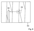
- Fig. 6 is explained a way to make the measurement independent of any camera vibrations and thereby increase the accuracy of measurement. Shown is a rectangular image field 652 of the first camera.
- a smaller rectangular measuring area 654 includes an almost vertically from top to bottom extending contour of a lying in the focus range of the camera, the camera facing winding section.
- the coordinates of the actual position of the observed structural element of the spring are determined by interpolation.
- the image of a reference element 680 can be seen, which is formed by a vertically oriented bolt, which with the help of a stable support is attached to the machine frame.
- the bolt protrudes from below into the image field and forms in the sharpness zone of the camera a sharp, vertical contour with a light / dark transition.
- the distance between the structural element and the edge of the reference element 680 facing the structural element is determined and the evaluation is taken as the basis. This measured distance is independent of any vibrations of the camera and any associated shifts of the image field relative to the observed spring. Any movements of the camera are therefore not included in the measurement errors.
- the measurements of the distance between the structural element of the helical spring (e.g., a winding section contour) and a virtual or physical reference element may be performed as described in the direction parallel to the axis 118 or in any other suitable directions obliquely thereto.
- a relative measurement with respect to a reference element which is formed by a part of the spring is also possible. If, for example, that in Fig. 3 shown image field 252 is sufficiently large to detect more windings in the longitudinal direction of the spring, the longitudinal distance between the measuring point 270 at the lying in the measuring range 254 winding contour and a closer to the forming tools, 3 or 4 turns remote, corresponding Windungskontur measured and based on the scheme.
- the first complete turn 214 or its machine-distant contour could serve as a reference element.
Landscapes
- Engineering & Computer Science (AREA)
- Mechanical Engineering (AREA)
- Wire Processing (AREA)
- Springs (AREA)
Claims (15)
- Procédé de fabrication de ressorts hélicoïdaux (200) par enroulement d'un ressort au moyen d'une machine (100) d'enroulement de ressorts à commande numérique, dans lequel un fil (115) est amené par un dispositif d'amenée (110) à un dispositif de façonnage (120) de la machine (100) d'enroulement de ressort sous la commande d'un programme de commande NC et est transformé en un ressort hélicoïdal (200) à l'aide d'outils (122; 124) du dispositif de façonnage (120), le procédé comportant les étapes suivantes :définition d'une géométrie de consigne souhaitée du ressort hélicoïdal (200) et d'un programme de commande NC qui convient pour former la géométrie de consigne,mesure d'une position effective d'un élément structurel sélectionné du ressort hélicoïdal par rapport à un élément de référence en au moins un instant de mesure situé après le début et avant la fin de la fabrication du ressort hélicoïdal, dans une plage de mesure (254) qui présente dans le sens de la longueur du ressort hélicoïdal une distance finie par rapport au dispositif de façonnage, la distance étant inférieure à la longueur totale du ressort hélicoïdal terminé,comparaison entre la position effective et une position de consigne de l'élément structurel à l'instant de mesure pour déterminer une différence effective de position qui représente la différence entre la position effective et la position de consigne à l'instant de mesure etcommande de l'ajustement d'au moins un outil (130), qui détermine le pas du ressort hélicoïdal, du dispositif de façonnage (120) en fonction de la différence de position.
- Procédé selon la revendication 1, dans lequel la distance de la plage de mesure par rapport au dispositif de façonnage est adaptée à la longueur totale du ressort hélicoïdal terminé, de telle sorte que la distance représente entre 5 % et 70 % et en particulier entre 10 % et 50 % de la longueur totale et/ou qu'un ou plusieurs enroulements du ressort soient situés à l'intérieur de la distance.
- Procédé selon les revendications 1 ou 2, dans lequel la mesure utilise une caméra (259) dotée d'un champ d'image bidimensionnel, la plage de mesure (254) étant située dans le champ d'image (252) de la caméra.
- Procédé selon l'une des revendications précédentes, dans lequel la mesure de la position effective est réalisée par rapport à un élément de référence fixe sur la machine.
- Procédé selon les revendications 3 et 4, qui utilise un élément de référence virtuel formé par un bord du champ d'image (252) de la caméra (259), de préférence par le bord latéral du champ d'image tourné vers le dispositif de façonnage, ou dans lequel un corps de référence fixé sur la machine et placé dans le champ d'image de la caméra à une distance de la plage de mesure est prévu, un élément du corps de référence et en particulier une arête rectiligne étant utilisé comme élément de référence pour la mesure.
- Procédé selon l'une des revendications précédentes, dans lequel l'élément structurel du ressort hélicoïdal sélectionné pour être utilisé dans la mesure est un contour, qui apparaît en ligne droite dans le champ d'image, d'une partie d'enroulement qui s'étend transversalement par rapport au sens de la longueur du ressort hélicoïdal et en particulier sous un angle compris entre environ 45° et environ 90° par rapport à ce sens de la longueur.
- Procédé selon l'une des revendications précédentes, dans lequel les coordonnées de la position de consigne de l'élément structurel à l'instant de mesure sont déduites d'une fonction temporelle de programmation, définie avant la mesure, des coordonnées de la position de consigne de l'élément structurel, la fonction temporelle de programmation prévue pour les coordonnées de la position de consigne de l'élément structurel étant déterminée de préférence expérimentellement sur la base d'au moins une opération de fabrication de référence d'un ressort hélicoïdal de référence.
- Procédé selon l'une des revendications précédentes, dans lequel pendant la fabrication du ressort hélicoïdal, plusieurs mesures sont exécutées à des instants de mesure successifs dans le temps, l'intervalle de temps étant adapté de préférence à la vitesse d'amenée du fil de telle sorte que dans un intervalle de temps qui s'écoule entre deux mesures immédiatement successives, au moins un enroulement soit formé et de préférence qu'entre un et deux enroulements soient formés pendant l'intervalle de temps.
- Procédé selon l'une des revendications précédentes, dans lequel plusieurs mesures sont exécutées pendant la formation d'une partie constante du ressort hélicoïdal et/ou dans lequel, à partir des valeurs effectives de plusieurs mesures successives, une valeur moyenne mobile est déterminée pour les valeurs effectives après un nombre prédéfini de mesures et en particulier après chaque mesure, l'évolution dans le temps de la valeur moyenne mobile étant de préférence affichée sur une unité d'affichage de la machine d'enroulement de ressort.
- Procédé selon l'une des revendications précédentes, dans lequel pour chaque différence de position déterminée, une valeur pondérée de différence, en particulier une valeur pondérée de différence proportionnelle à la différence de position, est déterminée, et la position de l'outil est modifiée sur la base de la valeur pondérée de différence.
- Procédé selon l'une des revendications précédentes, dans lequel, en particulier lors de la mesure d'une partie de ressorts présentant un pas variable, une première mesure est exécutée à un premier instant de mesure dans une première plage de mesure située à une première distance du dispositif de façonnage, une deuxième mesure est exécutée en un deuxième instant de mesure, différent du premier, dans une deuxième plage de mesure décalée par rapport à la première plage de mesure et située à une deuxième distance du dispositif de façonnage supérieure à la première distance, les résultats de la première mesure et de la deuxième mesure étant traités conjointement.
- Machine (100) d'enroulement de ressort destinée à fabriquer des ressorts hélicoïdaux (200) par enroulement d'un ressort sous la commande d'un programme de commande NC, la machine présentant un dispositif d'amenée (110) qui amène un fil (115) à un dispositif de façonnage (120), le dispositif de façonnage présentant au moins un outil d'enroulement (122, 124) qui définit essentiellement le diamètre du ressort hélicoïdal en une position prédéterminée, ainsi qu'au moins un outil (130) de formation d'un pas dont l'engagement sur le ressort hélicoïdal en formation définit le pas local du ressort hélicoïdal, caractérisée en ce que
la machine d'enroulement de ressort présente pour la mesure d'une position effective d'un élément structurel sélectionné du ressort hélicoïdal par rapport à un élément de référence une première caméra (259) disposée de telle sorte qu'une plage de mesure (254) située dans le champ d'image (252) de la première caméra saisisse une partie d'un tronçon de ressort à une distance finie (210) des outils du dispositif de façonnage (120) et qu'un dispositif de commande de la machine d'enroulement de ressort soit configuré en vue d'exécuter le procédé selon l'une des revendications précédentes. - Machine d'enroulement de ressort selon la revendication 12, dans laquelle la distance (210) est adaptée à la longueur totale du ressort hélicoïdal terminé de telle sorte que la distance représente entre 5 % et 70 % et en particulier entre 10 % et 50 % de la longueur totale et/ou qu'un ou plusieurs enroulements du ressort soient situés à l'intérieur de la distance.
- Machine d'enroulement de ressort selon les revendications 12 ou 13, dans laquelle la machine d'enroulement de ressort présente une deuxième caméra (260) disposée à distance de la première caméra (250) de telle sorte qu'une partie terminale libre (204) du ressort pénètre dans la plage de saisie de la deuxième caméra dans la phase finale de la fabrication du ressort hélicoïdal.
- Produit de programme informatique conservé en particulier sur un support lisible par ordinateur ou réalisé sous la forme de signaux, le produit de programme informatique ayant pour effet, lorsqu'il est chargé dans la mémoire d'un dispositif de commande assisté par ordinateur d'une machine d'enroulement de ressort à commande numérique selon l'une des revendications 12 à 14 et lorsqu'il est exécuté par le dispositif de commande, que la machine d'enroulement de ressort exécute un procédé selon l'une des revendications 1 à 11.
Priority Applications (4)
| Application Number | Priority Date | Filing Date | Title |
|---|---|---|---|
| JP2011058680A JP5666954B2 (ja) | 2010-04-06 | 2011-03-17 | ばね巻きによって螺旋ばねを製造するための方法および装置 |
| RU2011112497/02A RU2469811C1 (ru) | 2010-04-06 | 2011-04-04 | Способ изготовления винтовой пружины путем навивки и пружинонавивочная машина |
| CN201110085016.3A CN102233399B (zh) | 2010-04-06 | 2011-04-06 | 通过卷绕弹簧来生产螺旋弹簧的方法和装置 |
| BRPI1101836-4A BRPI1101836A2 (pt) | 2010-04-06 | 2011-04-06 | método e aparelho para a produção de molas helicoidais por meio de enrolamento de mola |
Applications Claiming Priority (1)
| Application Number | Priority Date | Filing Date | Title |
|---|---|---|---|
| DE102010014385A DE102010014385B4 (de) | 2010-04-06 | 2010-04-06 | Verfahren und Vorrichtung zur Herstellung von Schraubenfedern durch Federwinden, sowie Federwindemaschine |
Publications (2)
| Publication Number | Publication Date |
|---|---|
| EP2374551A1 EP2374551A1 (fr) | 2011-10-12 |
| EP2374551B1 true EP2374551B1 (fr) | 2012-11-28 |
Family
ID=44317626
Family Applications (1)
| Application Number | Title | Priority Date | Filing Date |
|---|---|---|---|
| EP11001528A Active EP2374551B1 (fr) | 2010-04-06 | 2011-02-24 | Procédé et dispositif de fabrication de ressorts cylindriques par enroulements de ressort |
Country Status (7)
| Country | Link |
|---|---|
| US (1) | US9566637B2 (fr) |
| EP (1) | EP2374551B1 (fr) |
| JP (1) | JP5666954B2 (fr) |
| CN (1) | CN102233399B (fr) |
| BR (1) | BRPI1101836A2 (fr) |
| DE (1) | DE102010014385B4 (fr) |
| RU (1) | RU2469811C1 (fr) |
Cited By (1)
| Publication number | Priority date | Publication date | Assignee | Title |
|---|---|---|---|---|
| WO2025146373A1 (fr) * | 2024-01-05 | 2025-07-10 | ThyssenKrupp Federn und Stabilisatoren GmbH | Procédé mis en œuvre par ordinateur pour régler le centre de force ou la force transversale d'un ressort hélicoïdal |
Families Citing this family (22)
| Publication number | Priority date | Publication date | Assignee | Title |
|---|---|---|---|---|
| JP2013176797A (ja) * | 2012-02-29 | 2013-09-09 | Asahi- Seiki Manufacturing Co Ltd | コイルばね成形装置及びばね長計測装置 |
| DE102012204344B4 (de) | 2012-03-19 | 2016-01-21 | Wafios Ag | Umformmaschine |
| DE102012204513B3 (de) | 2012-03-21 | 2013-09-19 | Wafios Ag | Verfahren und Vorrichtung zur Herstellung von Schraubenfedern durch Federwinden |
| DE102013207028B3 (de) * | 2013-04-18 | 2014-06-26 | Wafios Ag | Federwindemaschine mit einstellbarer Schnitteinrichtung |
| ITMI20131181A1 (it) | 2013-07-15 | 2015-01-16 | Simplex Rapid S R L | Dispositivo per la formazione di molle |
| GB201313101D0 (en) * | 2013-07-23 | 2013-09-04 | Dunlop Oil & Marine Ltd | Helical wire forming tool for hose construction |
| JP6420690B2 (ja) * | 2015-02-26 | 2018-11-07 | 日本発條株式会社 | コイリングマシンと、コイルばねの製造方法 |
| DE102015208346B4 (de) * | 2015-05-06 | 2017-02-23 | Wafios Aktiengesellschaft | Einzugseinrichtung für Umformmaschine |
| CN104976260B (zh) * | 2015-06-18 | 2017-12-29 | 东莞市佳铠精密金属制品有限公司 | 多螺旋弹簧及其制备装置和成型方法 |
| CN105195650B (zh) * | 2015-10-15 | 2017-05-31 | 山西北方机械制造有限责任公司 | 一种基于自动卷簧机的压缩弹簧卷簧方法 |
| GB201609642D0 (en) * | 2016-06-02 | 2016-07-20 | Harrison Spinks Components Ltd | Wire shaping apparatus and method |
| JP7121131B2 (ja) * | 2018-09-06 | 2022-08-17 | 日本発條株式会社 | アークスプリングの成形方法及び成形装置 |
| CN109500303B (zh) * | 2018-11-22 | 2020-04-07 | 安徽伟豪预应力设备有限公司 | 一种两用式预应力螺旋筋卷绕加工装置 |
| KR102196035B1 (ko) * | 2018-12-26 | 2020-12-29 | (주)미래컴퍼니 | 펄스 위상 이동을 이용한 3차원 거리측정 카메라의 비선형 거리 오차 보정 방법 |
| CN109822018B (zh) * | 2019-03-11 | 2024-03-22 | 佛山市昱纶机械有限公司 | 一种多线弹簧机头 |
| DE102020209068A1 (de) | 2020-07-20 | 2022-01-20 | Wafios Aktiengesellschaft | Verfahren und Federwindemaschine zur Herstellung von Schraubenfedern |
| CN113414326B (zh) * | 2021-06-24 | 2024-04-19 | 黄山立铖精密弹簧有限公司 | 一种圆柱弹簧生产用成型装置及其成型方法 |
| CN113617971A (zh) * | 2021-08-11 | 2021-11-09 | 中国电子科技集团公司第三十八研究所 | 一种大螺距大长径比螺旋天线的成型装置 |
| DE102021211526A1 (de) | 2021-10-13 | 2023-04-13 | Wafios Aktiengesellschaft | Verfahren und System zur Herstellung von Schraubenfedern |
| CN114632897A (zh) * | 2022-04-11 | 2022-06-17 | 惠州市侨鼎自动化设备有限公司 | 一种线材成型机的参数修正方法及线材成型方法 |
| JP7438648B1 (ja) | 2023-07-10 | 2024-02-27 | 旭精機工業株式会社 | 計測装置及び成形機 |
| TWI852714B (zh) * | 2023-08-04 | 2024-08-11 | 自如行自動化有限公司 | 彈簧機之即時補正設備 |
Family Cites Families (22)
| Publication number | Priority date | Publication date | Assignee | Title |
|---|---|---|---|---|
| SU421416A1 (fr) * | 1972-06-12 | 1974-03-30 | ||
| JPH02192839A (ja) | 1989-01-20 | 1990-07-30 | Kato Hatsujo Kaisha Ltd | 圧縮コイルばね及びその製造方法並びにその製造装置 |
| RU1818168C (ru) * | 1990-05-21 | 1993-05-30 | Научно-производственное объединение "Кибернетика" | Автомат дл навивки пружин |
| JP3172221B2 (ja) | 1991-11-18 | 2001-06-04 | 株式会社東京コイリングマシン製作所 | コイルばねの製造方法 |
| US5477715A (en) | 1992-04-08 | 1995-12-26 | Reell Precision Manufacturing Corporation | Adaptive spring winding device and method |
| DE4229294C1 (de) | 1992-09-02 | 1993-12-16 | Wafios Maschinen Wagner | Vorrichtung zum Formen von Draht |
| JP2978076B2 (ja) * | 1994-10-07 | 1999-11-15 | 旭精機工業株式会社 | Ncコイルばね製造機の自由長管理装置 |
| US6073056A (en) * | 1997-04-08 | 2000-06-06 | Larry J. Winget | Method and system for building a data model of a physical part in a data format useful for and reproduction of the part |
| US5875664A (en) * | 1997-12-23 | 1999-03-02 | L&P Property Management Company | Programmable servo-motor quality controlled continuous multiple coil spring forming method and apparatus |
| JP3810989B2 (ja) * | 2000-06-30 | 2006-08-16 | 旭精機工業株式会社 | コイルばねの成形方法 |
| DE10063786A1 (de) * | 2000-12-21 | 2002-07-04 | Tech Federn Gmbh Otto Joos | Vorrichtung und Verfahren zum Vermessen eines Gegenstandes |
| JP2003136171A (ja) | 2001-10-29 | 2003-05-14 | Yamani Hatsujo Kk | コイルバネにおけるコイル外径の検出装置 |
| US6909502B2 (en) * | 2001-12-27 | 2005-06-21 | General Electric | Method and apparatus for measuring ripple and distortion in a transparent material |
| ITMI20030341A1 (it) * | 2003-02-26 | 2004-08-27 | Easydur Italiana Di Renato Affri | Sistema per controllare la fabbricazione di una molla. |
| WO2004101193A1 (fr) * | 2003-05-13 | 2004-11-25 | Spühl AG St. Gallen | Machine a fabriquer des ressorts helicoidaux et procede de commande de ladite machine |
| ITMI20031769A1 (it) | 2003-09-16 | 2005-03-17 | Microstudio S A S Di Calafa Giamp Aolo & C | Metodo per misurare in produzione le dimensioni di molle metalliche |
| WO2006029214A2 (fr) * | 2004-09-08 | 2006-03-16 | Tru Tech Systems, Inc. | Systeme de comparateur/projecteur de profil d'inspection automatique |
| JP4612552B2 (ja) | 2006-02-10 | 2011-01-12 | 旭精機工業株式会社 | 画像処理装置及びばね成形機 |
| DE102006048642A1 (de) * | 2006-10-13 | 2008-04-17 | Huang, Jin-Tarng, Dongguan | Polyfunktionelle Federherstellungsvorrichtung |
| JP4317252B2 (ja) * | 2007-06-05 | 2009-08-19 | 株式会社板屋製作所 | らせん状部品の製造装置 |
| US8136379B2 (en) * | 2007-06-05 | 2012-03-20 | Kabushiki Kaisha Itaya Seisaku Sho | Helical part manufacturing apparatus and control method thereof |
| DE102010010895B3 (de) * | 2010-03-03 | 2011-10-06 | Wafios Ag | Verfahren zur Herstellung von Schraubenfedern durch Federwinden, sowie Federwindemaschine |
-
2010
- 2010-04-06 DE DE102010014385A patent/DE102010014385B4/de active Active
- 2010-10-08 US US12/900,793 patent/US9566637B2/en active Active
-
2011
- 2011-02-24 EP EP11001528A patent/EP2374551B1/fr active Active
- 2011-03-17 JP JP2011058680A patent/JP5666954B2/ja active Active
- 2011-04-04 RU RU2011112497/02A patent/RU2469811C1/ru active
- 2011-04-06 CN CN201110085016.3A patent/CN102233399B/zh not_active Expired - Fee Related
- 2011-04-06 BR BRPI1101836-4A patent/BRPI1101836A2/pt active Search and Examination
Cited By (1)
| Publication number | Priority date | Publication date | Assignee | Title |
|---|---|---|---|---|
| WO2025146373A1 (fr) * | 2024-01-05 | 2025-07-10 | ThyssenKrupp Federn und Stabilisatoren GmbH | Procédé mis en œuvre par ordinateur pour régler le centre de force ou la force transversale d'un ressort hélicoïdal |
Also Published As
| Publication number | Publication date |
|---|---|
| RU2469811C1 (ru) | 2012-12-20 |
| JP5666954B2 (ja) | 2015-02-12 |
| JP2011218446A (ja) | 2011-11-04 |
| CN102233399A (zh) | 2011-11-09 |
| US20110239718A1 (en) | 2011-10-06 |
| US9566637B2 (en) | 2017-02-14 |
| BRPI1101836A2 (pt) | 2012-08-21 |
| DE102010014385A1 (de) | 2011-10-06 |
| CN102233399B (zh) | 2014-03-19 |
| EP2374551A1 (fr) | 2011-10-12 |
| RU2011112497A (ru) | 2012-10-10 |
| DE102010014385B4 (de) | 2011-12-08 |
Similar Documents
| Publication | Publication Date | Title |
|---|---|---|
| EP2374551B1 (fr) | Procédé et dispositif de fabrication de ressorts cylindriques par enroulements de ressort | |
| DE102010014386B4 (de) | Verfahren zur Herstellung von Schraubenfedern durch Federwinden, sowie Federwindemaschine | |
| DE102012204513B3 (de) | Verfahren und Vorrichtung zur Herstellung von Schraubenfedern durch Federwinden | |
| DE102010010895B3 (de) | Verfahren zur Herstellung von Schraubenfedern durch Federwinden, sowie Federwindemaschine | |
| EP2353748B1 (fr) | Procédé et dispositif de fabrication d'une pièce pliée | |
| EP3126073B1 (fr) | Procédé et machine à enrouler les ressorts pour la production de ressorts hélicoïdaux par enroulement | |
| EP2826572B1 (fr) | Enrouleuse de ressorts avec dispositif de coupe réglable | |
| EP0796158B1 (fr) | Procede et dispositif de production optimisee de ressorts helicoidaux sur des machines automatiques a enrouler les ressorts | |
| EP4182101B1 (fr) | Procédé et machine d'enroulement de ressorts pour produire des ressorts hélicoïdaux | |
| DE102015002040B4 (de) | Numerische Steuerung für eine Laserbearbeitungsmaschine | |
| DE102014108956A1 (de) | Vorrichtung zum Entgraten mit visuellem Sensor und Kraftsensor | |
| WO2016177582A1 (fr) | Procédé de fabrication de pièces formées et machine de formage pour la mise en œuvre dudit procédé | |
| DE102013011307A1 (de) | Verfahren und Vorrichtung zur Werkzeugmessung oder Werkstückmessung | |
| DE3804913C2 (fr) | ||
| DE102019131992B4 (de) | Werkzeugmaschine | |
| EP3720623B1 (fr) | Système d'étirement, de courbure et de redressement et son procédé d'actionnement | |
| DE102019111940A1 (de) | Umformmaschine zum Herstellen von Biegeteilen aus isoliertem länglichem Material | |
| DE102017200365B4 (de) | Verfahren und Vorrichtung zum Richten eines Metallbandes | |
| EP3537102A1 (fr) | Procédé et dispositif d'augmentation du rendement pour une précision suffisante lors de la mesure de pièces à usiner | |
| EP3970913A1 (fr) | Procédé de production par enlèvement de copeaux de structures sur des surfaces de pièce ainsi que machine d'usinage | |
| EP2937753B1 (fr) | Procédé de mesure d'outils et machine-outil et/ou de production fonctionnant selon le procédé | |
| DE102017106559B4 (de) | Auslegung oder Durchführung einer Bewegungsaufgabe einer bewegten Masse in einer mechanischen Anlage entlang zumindest einer Bewegungsachse | |
| DE3931066A1 (de) | Kantensteuerungsvorrichtung | |
| EP2683503B1 (fr) | Procédé et dispositif de pliage de tôles à précision angulaire | |
| EP2169098A1 (fr) | Procédé destiné au fonctionnement d'une machine de coupe conique et machine de coupe conique |
Legal Events
| Date | Code | Title | Description |
|---|---|---|---|
| PUAI | Public reference made under article 153(3) epc to a published international application that has entered the european phase |
Free format text: ORIGINAL CODE: 0009012 |
|
| AK | Designated contracting states |
Kind code of ref document: A1 Designated state(s): AL AT BE BG CH CY CZ DE DK EE ES FI FR GB GR HR HU IE IS IT LI LT LU LV MC MK MT NL NO PL PT RO RS SE SI SK SM TR |
|
| AX | Request for extension of the european patent |
Extension state: BA ME |
|
| 17P | Request for examination filed |
Effective date: 20120112 |
|
| GRAP | Despatch of communication of intention to grant a patent |
Free format text: ORIGINAL CODE: EPIDOSNIGR1 |
|
| RIC1 | Information provided on ipc code assigned before grant |
Ipc: B21C 51/00 20060101AFI20120515BHEP Ipc: B21F 35/00 20060101ALI20120515BHEP Ipc: B21F 3/02 20060101ALI20120515BHEP |
|
| GRAS | Grant fee paid |
Free format text: ORIGINAL CODE: EPIDOSNIGR3 |
|
| GRAA | (expected) grant |
Free format text: ORIGINAL CODE: 0009210 |
|
| AK | Designated contracting states |
Kind code of ref document: B1 Designated state(s): AL AT BE BG CH CY CZ DE DK EE ES FI FR GB GR HR HU IE IS IT LI LT LU LV MC MK MT NL NO PL PT RO RS SE SI SK SM TR |
|
| REG | Reference to a national code |
Ref country code: GB Ref legal event code: FG4D Free format text: NOT ENGLISH |
|
| REG | Reference to a national code |
Ref country code: CH Ref legal event code: EP |
|
| REG | Reference to a national code |
Ref country code: AT Ref legal event code: REF Ref document number: 585860 Country of ref document: AT Kind code of ref document: T Effective date: 20121215 |
|
| REG | Reference to a national code |
Ref country code: IE Ref legal event code: FG4D Free format text: LANGUAGE OF EP DOCUMENT: GERMAN |
|
| REG | Reference to a national code |
Ref country code: DE Ref legal event code: R096 Ref document number: 502011000223 Country of ref document: DE Effective date: 20130124 |
|
| REG | Reference to a national code |
Ref country code: NL Ref legal event code: VDEP Effective date: 20121128 |
|
| REG | Reference to a national code |
Ref country code: LT Ref legal event code: MG4D |
|
| PG25 | Lapsed in a contracting state [announced via postgrant information from national office to epo] |
Ref country code: ES Free format text: LAPSE BECAUSE OF FAILURE TO SUBMIT A TRANSLATION OF THE DESCRIPTION OR TO PAY THE FEE WITHIN THE PRESCRIBED TIME-LIMIT Effective date: 20130311 Ref country code: LT Free format text: LAPSE BECAUSE OF FAILURE TO SUBMIT A TRANSLATION OF THE DESCRIPTION OR TO PAY THE FEE WITHIN THE PRESCRIBED TIME-LIMIT Effective date: 20121128 Ref country code: FI Free format text: LAPSE BECAUSE OF FAILURE TO SUBMIT A TRANSLATION OF THE DESCRIPTION OR TO PAY THE FEE WITHIN THE PRESCRIBED TIME-LIMIT Effective date: 20121128 Ref country code: NO Free format text: LAPSE BECAUSE OF FAILURE TO SUBMIT A TRANSLATION OF THE DESCRIPTION OR TO PAY THE FEE WITHIN THE PRESCRIBED TIME-LIMIT Effective date: 20130228 Ref country code: SE Free format text: LAPSE BECAUSE OF FAILURE TO SUBMIT A TRANSLATION OF THE DESCRIPTION OR TO PAY THE FEE WITHIN THE PRESCRIBED TIME-LIMIT Effective date: 20121128 |
|
| PG25 | Lapsed in a contracting state [announced via postgrant information from national office to epo] |
Ref country code: PT Free format text: LAPSE BECAUSE OF FAILURE TO SUBMIT A TRANSLATION OF THE DESCRIPTION OR TO PAY THE FEE WITHIN THE PRESCRIBED TIME-LIMIT Effective date: 20130328 Ref country code: SI Free format text: LAPSE BECAUSE OF FAILURE TO SUBMIT A TRANSLATION OF THE DESCRIPTION OR TO PAY THE FEE WITHIN THE PRESCRIBED TIME-LIMIT Effective date: 20121128 Ref country code: GR Free format text: LAPSE BECAUSE OF FAILURE TO SUBMIT A TRANSLATION OF THE DESCRIPTION OR TO PAY THE FEE WITHIN THE PRESCRIBED TIME-LIMIT Effective date: 20130301 Ref country code: LV Free format text: LAPSE BECAUSE OF FAILURE TO SUBMIT A TRANSLATION OF THE DESCRIPTION OR TO PAY THE FEE WITHIN THE PRESCRIBED TIME-LIMIT Effective date: 20121128 Ref country code: PL Free format text: LAPSE BECAUSE OF FAILURE TO SUBMIT A TRANSLATION OF THE DESCRIPTION OR TO PAY THE FEE WITHIN THE PRESCRIBED TIME-LIMIT Effective date: 20121128 |
|
| PG25 | Lapsed in a contracting state [announced via postgrant information from national office to epo] |
Ref country code: RS Free format text: LAPSE BECAUSE OF FAILURE TO SUBMIT A TRANSLATION OF THE DESCRIPTION OR TO PAY THE FEE WITHIN THE PRESCRIBED TIME-LIMIT Effective date: 20121128 Ref country code: SK Free format text: LAPSE BECAUSE OF FAILURE TO SUBMIT A TRANSLATION OF THE DESCRIPTION OR TO PAY THE FEE WITHIN THE PRESCRIBED TIME-LIMIT Effective date: 20121128 Ref country code: EE Free format text: LAPSE BECAUSE OF FAILURE TO SUBMIT A TRANSLATION OF THE DESCRIPTION OR TO PAY THE FEE WITHIN THE PRESCRIBED TIME-LIMIT Effective date: 20121128 Ref country code: DK Free format text: LAPSE BECAUSE OF FAILURE TO SUBMIT A TRANSLATION OF THE DESCRIPTION OR TO PAY THE FEE WITHIN THE PRESCRIBED TIME-LIMIT Effective date: 20121128 Ref country code: BG Free format text: LAPSE BECAUSE OF FAILURE TO SUBMIT A TRANSLATION OF THE DESCRIPTION OR TO PAY THE FEE WITHIN THE PRESCRIBED TIME-LIMIT Effective date: 20130228 Ref country code: CZ Free format text: LAPSE BECAUSE OF FAILURE TO SUBMIT A TRANSLATION OF THE DESCRIPTION OR TO PAY THE FEE WITHIN THE PRESCRIBED TIME-LIMIT Effective date: 20121128 |
|
| PG25 | Lapsed in a contracting state [announced via postgrant information from national office to epo] |
Ref country code: RO Free format text: LAPSE BECAUSE OF FAILURE TO SUBMIT A TRANSLATION OF THE DESCRIPTION OR TO PAY THE FEE WITHIN THE PRESCRIBED TIME-LIMIT Effective date: 20121128 Ref country code: NL Free format text: LAPSE BECAUSE OF FAILURE TO SUBMIT A TRANSLATION OF THE DESCRIPTION OR TO PAY THE FEE WITHIN THE PRESCRIBED TIME-LIMIT Effective date: 20121128 |
|
| BERE | Be: lapsed |
Owner name: WAFIOS A.G. Effective date: 20130228 |
|
| PG25 | Lapsed in a contracting state [announced via postgrant information from national office to epo] |
Ref country code: MC Free format text: LAPSE BECAUSE OF NON-PAYMENT OF DUE FEES Effective date: 20130228 |
|
| PLBE | No opposition filed within time limit |
Free format text: ORIGINAL CODE: 0009261 |
|
| STAA | Information on the status of an ep patent application or granted ep patent |
Free format text: STATUS: NO OPPOSITION FILED WITHIN TIME LIMIT |
|
| 26N | No opposition filed |
Effective date: 20130829 |
|
| REG | Reference to a national code |
Ref country code: FR Ref legal event code: ST Effective date: 20131031 |
|
| PG25 | Lapsed in a contracting state [announced via postgrant information from national office to epo] |
Ref country code: HR Free format text: LAPSE BECAUSE OF FAILURE TO SUBMIT A TRANSLATION OF THE DESCRIPTION OR TO PAY THE FEE WITHIN THE PRESCRIBED TIME-LIMIT Effective date: 20121128 Ref country code: CY Free format text: LAPSE BECAUSE OF FAILURE TO SUBMIT A TRANSLATION OF THE DESCRIPTION OR TO PAY THE FEE WITHIN THE PRESCRIBED TIME-LIMIT Effective date: 20121128 |
|
| REG | Reference to a national code |
Ref country code: IE Ref legal event code: MM4A |
|
| REG | Reference to a national code |
Ref country code: DE Ref legal event code: R097 Ref document number: 502011000223 Country of ref document: DE Effective date: 20130829 |
|
| PG25 | Lapsed in a contracting state [announced via postgrant information from national office to epo] |
Ref country code: AL Free format text: LAPSE BECAUSE OF FAILURE TO SUBMIT A TRANSLATION OF THE DESCRIPTION OR TO PAY THE FEE WITHIN THE PRESCRIBED TIME-LIMIT Effective date: 20121128 Ref country code: IE Free format text: LAPSE BECAUSE OF NON-PAYMENT OF DUE FEES Effective date: 20130224 Ref country code: FR Free format text: LAPSE BECAUSE OF NON-PAYMENT OF DUE FEES Effective date: 20130228 Ref country code: BE Free format text: LAPSE BECAUSE OF NON-PAYMENT OF DUE FEES Effective date: 20130228 |
|
| PG25 | Lapsed in a contracting state [announced via postgrant information from national office to epo] |
Ref country code: MT Free format text: LAPSE BECAUSE OF FAILURE TO SUBMIT A TRANSLATION OF THE DESCRIPTION OR TO PAY THE FEE WITHIN THE PRESCRIBED TIME-LIMIT Effective date: 20121128 |
|
| REG | Reference to a national code |
Ref country code: CH Ref legal event code: PL |
|
| PG25 | Lapsed in a contracting state [announced via postgrant information from national office to epo] |
Ref country code: CH Free format text: LAPSE BECAUSE OF NON-PAYMENT OF DUE FEES Effective date: 20140228 Ref country code: LI Free format text: LAPSE BECAUSE OF NON-PAYMENT OF DUE FEES Effective date: 20140228 |
|
| PG25 | Lapsed in a contracting state [announced via postgrant information from national office to epo] |
Ref country code: SM Free format text: LAPSE BECAUSE OF FAILURE TO SUBMIT A TRANSLATION OF THE DESCRIPTION OR TO PAY THE FEE WITHIN THE PRESCRIBED TIME-LIMIT Effective date: 20121128 |
|
| PG25 | Lapsed in a contracting state [announced via postgrant information from national office to epo] |
Ref country code: TR Free format text: LAPSE BECAUSE OF FAILURE TO SUBMIT A TRANSLATION OF THE DESCRIPTION OR TO PAY THE FEE WITHIN THE PRESCRIBED TIME-LIMIT Effective date: 20121128 |
|
| PG25 | Lapsed in a contracting state [announced via postgrant information from national office to epo] |
Ref country code: HU Free format text: LAPSE BECAUSE OF FAILURE TO SUBMIT A TRANSLATION OF THE DESCRIPTION OR TO PAY THE FEE WITHIN THE PRESCRIBED TIME-LIMIT; INVALID AB INITIO Effective date: 20110224 Ref country code: LU Free format text: LAPSE BECAUSE OF NON-PAYMENT OF DUE FEES Effective date: 20130224 Ref country code: MK Free format text: LAPSE BECAUSE OF FAILURE TO SUBMIT A TRANSLATION OF THE DESCRIPTION OR TO PAY THE FEE WITHIN THE PRESCRIBED TIME-LIMIT Effective date: 20121128 |
|
| GBPC | Gb: european patent ceased through non-payment of renewal fee |
Effective date: 20150224 |
|
| PG25 | Lapsed in a contracting state [announced via postgrant information from national office to epo] |
Ref country code: GB Free format text: LAPSE BECAUSE OF NON-PAYMENT OF DUE FEES Effective date: 20150224 |
|
| PG25 | Lapsed in a contracting state [announced via postgrant information from national office to epo] |
Ref country code: IS Free format text: LAPSE BECAUSE OF FAILURE TO SUBMIT A TRANSLATION OF THE DESCRIPTION OR TO PAY THE FEE WITHIN THE PRESCRIBED TIME-LIMIT Effective date: 20121128 |
|
| REG | Reference to a national code |
Ref country code: AT Ref legal event code: MM01 Ref document number: 585860 Country of ref document: AT Kind code of ref document: T Effective date: 20160224 |
|
| PG25 | Lapsed in a contracting state [announced via postgrant information from national office to epo] |
Ref country code: AT Free format text: LAPSE BECAUSE OF NON-PAYMENT OF DUE FEES Effective date: 20160224 |
|
| PGFP | Annual fee paid to national office [announced via postgrant information from national office to epo] |
Ref country code: DE Payment date: 20260217 Year of fee payment: 16 |
|
| PGFP | Annual fee paid to national office [announced via postgrant information from national office to epo] |
Ref country code: IT Payment date: 20260227 Year of fee payment: 16 |