EP2374563A1 - Anzeigestruktur einer Bohrmaschine - Google Patents
Anzeigestruktur einer Bohrmaschine Download PDFInfo
- Publication number
- EP2374563A1 EP2374563A1 EP10161773A EP10161773A EP2374563A1 EP 2374563 A1 EP2374563 A1 EP 2374563A1 EP 10161773 A EP10161773 A EP 10161773A EP 10161773 A EP10161773 A EP 10161773A EP 2374563 A1 EP2374563 A1 EP 2374563A1
- Authority
- EP
- European Patent Office
- Prior art keywords
- displacement
- control
- circuit board
- drilling machine
- guide body
- Prior art date
- Legal status (The legal status is an assumption and is not a legal conclusion. Google has not performed a legal analysis and makes no representation as to the accuracy of the status listed.)
- Withdrawn
Links
- 238000005553 drilling Methods 0.000 title claims abstract description 39
- 238000006073 displacement reaction Methods 0.000 claims abstract description 46
- 230000006698 induction Effects 0.000 claims abstract description 29
- 239000004973 liquid crystal related substance Substances 0.000 claims abstract description 15
- 238000003780 insertion Methods 0.000 claims description 4
- 230000037431 insertion Effects 0.000 claims description 4
- 238000012986 modification Methods 0.000 description 1
- 230000004048 modification Effects 0.000 description 1
Images



Classifications
-
- B—PERFORMING OPERATIONS; TRANSPORTING
- B23—MACHINE TOOLS; METAL-WORKING NOT OTHERWISE PROVIDED FOR
- B23B—TURNING; BORING
- B23B49/00—Measuring or gauging equipment on boring machines for positioning or guiding the drill; Devices for indicating failure of drills during boring; Centering devices for holes to be bored
-
- B—PERFORMING OPERATIONS; TRANSPORTING
- B23—MACHINE TOOLS; METAL-WORKING NOT OTHERWISE PROVIDED FOR
- B23B—TURNING; BORING
- B23B39/00—General-purpose boring or drilling machines or devices; Sets of boring and/or drilling machines
-
- B—PERFORMING OPERATIONS; TRANSPORTING
- B23—MACHINE TOOLS; METAL-WORKING NOT OTHERWISE PROVIDED FOR
- B23Q—DETAILS, COMPONENTS, OR ACCESSORIES FOR MACHINE TOOLS, e.g. ARRANGEMENTS FOR COPYING OR CONTROLLING; MACHINE TOOLS IN GENERAL CHARACTERISED BY THE CONSTRUCTION OF PARTICULAR DETAILS OR COMPONENTS; COMBINATIONS OR ASSOCIATIONS OF METAL-WORKING MACHINES, NOT DIRECTED TO A PARTICULAR RESULT
- B23Q1/00—Members which are comprised in the general build-up of a form of machine, particularly relatively large fixed members
- B23Q1/0009—Energy-transferring means or control lines for movable machine parts; Control panels or boxes; Control parts
- B23Q1/0045—Control panels or boxes
-
- B—PERFORMING OPERATIONS; TRANSPORTING
- B23—MACHINE TOOLS; METAL-WORKING NOT OTHERWISE PROVIDED FOR
- B23B—TURNING; BORING
- B23B2260/00—Details of constructional elements
- B23B2260/048—Devices to regulate the depth of cut
- B23B2260/0487—Depth indicators
-
- B—PERFORMING OPERATIONS; TRANSPORTING
- B23—MACHINE TOOLS; METAL-WORKING NOT OTHERWISE PROVIDED FOR
- B23B—TURNING; BORING
- B23B2260/00—Details of constructional elements
- B23B2260/128—Sensors
-
- Y—GENERAL TAGGING OF NEW TECHNOLOGICAL DEVELOPMENTS; GENERAL TAGGING OF CROSS-SECTIONAL TECHNOLOGIES SPANNING OVER SEVERAL SECTIONS OF THE IPC; TECHNICAL SUBJECTS COVERED BY FORMER USPC CROSS-REFERENCE ART COLLECTIONS [XRACs] AND DIGESTS
- Y10—TECHNICAL SUBJECTS COVERED BY FORMER USPC
- Y10T—TECHNICAL SUBJECTS COVERED BY FORMER US CLASSIFICATION
- Y10T408/00—Cutting by use of rotating axially moving tool
- Y10T408/21—Cutting by use of rotating axially moving tool with signal, indicator, illuminator or optical means
Definitions
- the present invention relates to a display structure of a drilling machine.
- Fig. 8 shows a conventional drilling machine comprising a feed device 30, a driving control unit 40 and a main base 50.
- the feed device 30 comprises a drilling head 31.
- the main base 50 comprises a support rod 51 which is slideably connected with a stand 510.
- the stand 510 can be adjusted upward or downward relative to the support rod 51.
- the driving control unit 40 and the feed device 30 are disposed on top of the support rod 51 of the main base 50.
- the driving control unit 40 drives the driving head 31 of the feed device 30 to feed and drill.
- the conventional drilling machine has some shortcomings:
- the inventor of the present invention has devoted himself based on his many years of practical experiences to improve the aforesaid problems of the conventional drilling machine.
- the primary object of the present invention is to improve a display structure of a drilling machine with rgeard to controllability and uniformity.
- the invention provides a display structure of a drilling machine which comprises a digital display control assembly.
- the digital display control assembly comprises a liquid crystal control panel, a control circuit board, a displacement induction controller and a battery seat.
- the liquid crystal control panel is electrically connected with the control circuit board.
- the control circuit board is electrically connected with the displacement induction controller.
- the control circuit board is further electrically connected with the battery seat.
- the displacement induction controller includes an engaging protrusion to engage with a displacement control linking seat of a feed guide body.
- the liquid crystal control panel of the digital display control assembly is adapted to input control signals, such as an initial point, a terminal point and a feed unit, and the control signals are sent to the displacement induction controller via the control circuit board.
- the displacement induction controller receives the signals and returns the signals to the control circuit board for controlling the upward/downward movement of the feed guide body.
- the feed guide body can carry out the same feed many times, controlling the feed depth and providing uniformity of drilling.
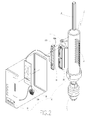
- a display structure of a drilling machine comprises a feed guide body 10 and a digital display control assembly 20.
- the feed guide body 10 comprises a displacement control linking seat 11 at a front side thereof.
- the displacement control linking seat 11 in a semi-cylinder shape has a first connecting hole 110 for insertion of a connecting member 110A.
- a guide spindle 12 is provided on top of feed guide body 10.
- the feed guide body 10 has a plurality of engaging portions 13 which are transversely disposed on a rear side of the feed guide body 10.
- the feed guide body 10 comprises a drilling head locking portion 14 at a lower end thereof.
- the digital display control assembly 20 comprises a liquid crystal control panel 21, a control circuit board 22, a displacement induction controller 23, and a battery seat 24.
- the control circuit board 22 is electrically connected with a buzzer 220.
- the displacement induction controller 23 comprises an engaging protrusion 230 which has a second connecting hole 230A.
- the liquid crystal control panel 21 is electrically connected with the control circuit board 22.
- the control circuit board 22 is electrically connected with the displacement induction controller 23.
- the control circuit board 22 is also electrically connected with the battery seat 24.
- the engaging protrusion 230 of the displacement induction controller 23 is engaged with the displacement control linking seat 11 of the feed guide body 10.
- the second connecting hole 230A of the engaging protrusion 230 is aligned with the first connecting hole 110 of the displacement control linking seat 11 of the feed guide body 10 and locked by the connecting member 110A. Accordingly, the display structure of the drilling machine of the present invention is assembled.
- Fig. 3 is a partially exploded view of the display structure of the drilling machine of the present invention.
- Fig. 4 is a schematic view showing the drilling machine in an advancing operation.
- Fig. 5 is a schematic view showing the drilling machine in a retracting operation.
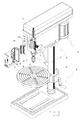
- the feed guide body 10 and the digital display control assembly 20 are coupled to a feed device 30.
- the feed device 30 is connected with a driving control unit 40 and a main base 50.
- the main body 50 comprises a support rod 51 which is provided with a movable stand 510.
- the driving control unit 40 drives the guide spindle 12 of the feed guide body 10.
- the liquid crystal control panel 21 is electrically connected with the control circuit board 22.
- the control circuit board 22 is electrically connected with the displacement induction controller 23.
- the control circuit board 22 is also electrically connected with the battery seat 24.
- the engaging protrusion 230 of the displacement induction controller 23 is engaged with the displacement control linking seat 11 of the feed guide body 10.
- the liquid crystal control panel 21 of the digital display control assembly 20 is adapted to input control signals, such as an initial point, a terminal point and a feed unit, and the control signals are sent to the displacement induction controller 23 via the control circuit board 22.
- the displacement induction controller 23 receives the signals and returns the signals to the control circuit board 22 for controlling the upward/downward movement of the feed guide body 10.
- the feed guide body 10 can carry out the same feed many times, controlling the feed depth well and providing uniformity of drilling.
- Fig. 6 is a front view showing the display structure of the drilling machine of the present invention coupled with the digital display control assembly 20.
- the liquid crystal control panel 21 of the digital display control assembly 20 further comprises a start switch 210, a feed unit control switch 211, an initial point switch 212 and a terminal point switch 213.
- the start switch 210 is pressed to turn on/off the machine.
- the start switch 210 is pressed for three seconds to delete the memory.
- the feed unit control switch 211 is pressed to select the feed unit in millimeter of inch.
- the initial point switch 212 and the terminal point switch 213 are adapted to set the feed depth of the feed guide body 10.
- Fig. 7 shows the display structure of the drilling machine according to a second embodiment of the present invention, which is substantially similar to the first embodiment as shown in Fig. 1 to Fig. 6 with the exceptions described hereinafter.
- the displacement control linking seat 11 of the feed guide body 10 is in a U shape and has a pair of first connecting holes 110 at two sides thereof for insertion of the connecting member 110A.
- the U-shaped displacement control linking seat 11 is adapted to engage with the engaging protrusion 230 of the displacement induction controller 23.
- the pair of first connecting holes 110 of the displacement control linking seat 11 of the feed guide body 10 is aligned with the second connecting hole 230A of the engaging protrusion 230 and locked by the connecting member 110A.
Landscapes
- Engineering & Computer Science (AREA)
- Mechanical Engineering (AREA)
- Drilling And Boring (AREA)
- Perforating, Stamping-Out Or Severing By Means Other Than Cutting (AREA)
- Liquid Crystal (AREA)
Applications Claiming Priority (1)
| Application Number | Priority Date | Filing Date | Title |
|---|---|---|---|
| TW099206298U TWM386950U (en) | 2010-04-09 | 2010-04-09 | Digital display structure for a drilling machine |
Publications (1)
| Publication Number | Publication Date |
|---|---|
| EP2374563A1 true EP2374563A1 (de) | 2011-10-12 |
Family
ID=44070593
Family Applications (1)
| Application Number | Title | Priority Date | Filing Date |
|---|---|---|---|
| EP10161773A Withdrawn EP2374563A1 (de) | 2010-04-09 | 2010-05-03 | Anzeigestruktur einer Bohrmaschine |
Country Status (3)
| Country | Link |
|---|---|
| US (1) | US20110250026A1 (de) |
| EP (1) | EP2374563A1 (de) |
| TW (1) | TWM386950U (de) |
Cited By (1)
| Publication number | Priority date | Publication date | Assignee | Title |
|---|---|---|---|---|
| CN105195772A (zh) * | 2015-10-20 | 2015-12-30 | 无锡格莱德科技有限公司 | 一种配件打孔装置 |
Families Citing this family (4)
| Publication number | Priority date | Publication date | Assignee | Title |
|---|---|---|---|---|
| JP5948280B2 (ja) * | 2013-05-30 | 2016-07-06 | 日東工器株式会社 | バッテリ式穿孔機 |
| US9889508B2 (en) | 2014-08-28 | 2018-02-13 | Hougen Manufacturing, Inc. | Magnetically mountable portable drill assembly |
| USD774570S1 (en) * | 2014-08-28 | 2016-12-20 | Hougen Manufacturing, Inc. | Magnetic base with illuminator for magnetically mountable portable drill |
| CN105397135A (zh) * | 2015-11-13 | 2016-03-16 | 太仓井林机械科技有限公司 | 一种自动化多工件钻孔装置 |
Citations (7)
| Publication number | Priority date | Publication date | Assignee | Title |
|---|---|---|---|---|
| US4317176A (en) * | 1980-03-24 | 1982-02-23 | Black & Decker Inc. | Microcomputer controlled power tool |
| DE3221709A1 (de) * | 1982-06-09 | 1983-12-15 | Robert 5446 Engeln Wolff | Bohrstaender mit bohrhubanzeige |
| DE3324428A1 (de) * | 1982-07-09 | 1984-01-12 | Black & Decker, Inc. (eine Gesellschaft n.d.Ges.d. Staates Delaware), 19711 Newark, Del. | Saeulenbohrmaschine |
| JPS62103517A (ja) * | 1985-10-31 | 1987-05-14 | Pentel Kk | 位置検出装置 |
| EP0254768A2 (de) * | 1986-07-28 | 1988-02-03 | Dieter Kühne | Gewindebohrmaschine |
| US6002250A (en) * | 1996-05-13 | 1999-12-14 | Mitutoyo Corporation | Electronic linear scale using a self-contained, low-power inductive position transducer |
| US20080166193A1 (en) * | 2007-01-10 | 2008-07-10 | Rudolf Fuchs | Stationary power drill |
Family Cites Families (9)
| Publication number | Priority date | Publication date | Assignee | Title |
|---|---|---|---|---|
| JPH077082Y2 (ja) * | 1989-03-10 | 1995-02-22 | ブラザー工業株式会社 | 往復移動体のストローク制御装置 |
| GB9320181D0 (en) * | 1993-09-30 | 1993-11-17 | Black & Decker Inc | Improvements in and relating to power tools |
| US5941663A (en) * | 1998-04-08 | 1999-08-24 | Elrod; Dwayne S. | Automated quill drive assembly for a milling machine |
| JP3741248B2 (ja) * | 1998-06-02 | 2006-02-01 | 日立ビアメカニクス株式会社 | プリント基板の穴明け装置及び保守方法 |
| JP2002018680A (ja) * | 2000-07-10 | 2002-01-22 | Mitsubishi Electric Corp | 工作機械 |
| DE102005049130A1 (de) * | 2005-10-14 | 2007-04-19 | Robert Bosch Gmbh | Handwerkzeugmaschine |
| CN101346204B (zh) * | 2005-12-26 | 2010-12-29 | 日东工器株式会社 | 移动式钻床 |
| US8310533B2 (en) * | 2006-03-27 | 2012-11-13 | GE Sensing & Inspection Technologies, LP | Inspection apparatus for inspecting articles |
| US20110088921A1 (en) * | 2008-07-25 | 2011-04-21 | Sylvain Forgues | Pneumatic hand tool rotational speed control method and portable apparatus |
-
2010
- 2010-04-09 TW TW099206298U patent/TWM386950U/zh not_active IP Right Cessation
- 2010-04-23 US US12/766,020 patent/US20110250026A1/en not_active Abandoned
- 2010-05-03 EP EP10161773A patent/EP2374563A1/de not_active Withdrawn
Patent Citations (7)
| Publication number | Priority date | Publication date | Assignee | Title |
|---|---|---|---|---|
| US4317176A (en) * | 1980-03-24 | 1982-02-23 | Black & Decker Inc. | Microcomputer controlled power tool |
| DE3221709A1 (de) * | 1982-06-09 | 1983-12-15 | Robert 5446 Engeln Wolff | Bohrstaender mit bohrhubanzeige |
| DE3324428A1 (de) * | 1982-07-09 | 1984-01-12 | Black & Decker, Inc. (eine Gesellschaft n.d.Ges.d. Staates Delaware), 19711 Newark, Del. | Saeulenbohrmaschine |
| JPS62103517A (ja) * | 1985-10-31 | 1987-05-14 | Pentel Kk | 位置検出装置 |
| EP0254768A2 (de) * | 1986-07-28 | 1988-02-03 | Dieter Kühne | Gewindebohrmaschine |
| US6002250A (en) * | 1996-05-13 | 1999-12-14 | Mitutoyo Corporation | Electronic linear scale using a self-contained, low-power inductive position transducer |
| US20080166193A1 (en) * | 2007-01-10 | 2008-07-10 | Rudolf Fuchs | Stationary power drill |
Cited By (1)
| Publication number | Priority date | Publication date | Assignee | Title |
|---|---|---|---|---|
| CN105195772A (zh) * | 2015-10-20 | 2015-12-30 | 无锡格莱德科技有限公司 | 一种配件打孔装置 |
Also Published As
| Publication number | Publication date |
|---|---|
| US20110250026A1 (en) | 2011-10-13 |
| TWM386950U (en) | 2010-08-21 |
Similar Documents
| Publication | Publication Date | Title |
|---|---|---|
| US20110250026A1 (en) | Display structure of a drilling machine | |
| US8913376B2 (en) | Expandable keyboard device | |
| US20080300615A1 (en) | Wireless tattoo applicator | |
| DE102013112677B4 (de) | Handbedienteil, Handbediensystem, Möbelsteuerungssystem, Bett und Sessel | |
| CN108990425B (zh) | 电源适配器 | |
| US20020085338A1 (en) | Portable computer with a detachable keyboard device | |
| JP6635962B2 (ja) | カーテン開閉装置及びカーテン開閉システム | |
| WO2010107799A3 (en) | Portable electronic devices with adjustable display orientation | |
| EP1243997A3 (de) | Steuereinheit eines in einem Fahrzeug eingebautem Gerätes | |
| JP2007073411A (ja) | 可撓性導体用コネクタ | |
| KR102151010B1 (ko) | 멀티니들모듈 및 그것의 사용을 위한 자동시술장치 | |
| US9677859B1 (en) | Lighted arrow nock | |
| KR200454809Y1 (ko) | 휴대 단말기 결합이 가능한 디스플레이 장치 | |
| US11281311B2 (en) | Switch module and wireless mouse including the same | |
| EP3136380B1 (de) | Elektronisches musikinstrument | |
| KR20190118460A (ko) | 피부시술용 멀티니들모듈을 위한 자동시술장치 | |
| JP3109633U (ja) | 検出電気コネクタ | |
| US20200039050A1 (en) | Device for Installing Expansion Bolts | |
| KR101860672B1 (ko) | 시각장애인용 점자표시장치의 제어방법 | |
| CN208111822U (zh) | 插头锁紧组件及超声设备 | |
| CN116129783B (zh) | Led显示驱动芯片 | |
| CN107168504B (zh) | 台式电脑主机开关电源辅助按压装置 | |
| CN220695671U (zh) | 微针经皮给药装置 | |
| CN214757265U (zh) | 一种控制柜发泡箱辅助拼装自动调节装置 | |
| KR20110123058A (ko) | 입출식 입력장치 및 이를 구비한 디스플레이 장치 |
Legal Events
| Date | Code | Title | Description |
|---|---|---|---|
| PUAI | Public reference made under article 153(3) epc to a published international application that has entered the european phase |
Free format text: ORIGINAL CODE: 0009012 |
|
| AK | Designated contracting states |
Kind code of ref document: A1 Designated state(s): AL AT BE BG CH CY CZ DE DK EE ES FI FR GB GR HR HU IE IS IT LI LT LU LV MC MK MT NL NO PL PT RO SE SI SK SM TR |
|
| AX | Request for extension of the european patent |
Extension state: BA ME RS |
|
| 17P | Request for examination filed |
Effective date: 20120326 |
|
| 17Q | First examination report despatched |
Effective date: 20130523 |
|
| STAA | Information on the status of an ep patent application or granted ep patent |
Free format text: STATUS: THE APPLICATION IS DEEMED TO BE WITHDRAWN |
|
| 18D | Application deemed to be withdrawn |
Effective date: 20131003 |