EP2374569A2 - Dispositif de traitement au laser et procédé de fabrication d'un outil à rotation symétrique - Google Patents
Dispositif de traitement au laser et procédé de fabrication d'un outil à rotation symétrique Download PDFInfo
- Publication number
- EP2374569A2 EP2374569A2 EP20110158090 EP11158090A EP2374569A2 EP 2374569 A2 EP2374569 A2 EP 2374569A2 EP 20110158090 EP20110158090 EP 20110158090 EP 11158090 A EP11158090 A EP 11158090A EP 2374569 A2 EP2374569 A2 EP 2374569A2
- Authority
- EP
- European Patent Office
- Prior art keywords
- blank
- laser
- laser beam
- pulse
- process gas
- Prior art date
- Legal status (The legal status is an assumption and is not a legal conclusion. Google has not performed a legal analysis and makes no representation as to the accuracy of the status listed.)
- Granted
Links
Images




Classifications
-
- B—PERFORMING OPERATIONS; TRANSPORTING
- B23—MACHINE TOOLS; METAL-WORKING NOT OTHERWISE PROVIDED FOR
- B23K—SOLDERING OR UNSOLDERING; WELDING; CLADDING OR PLATING BY SOLDERING OR WELDING; CUTTING BY APPLYING HEAT LOCALLY, e.g. FLAME CUTTING; WORKING BY LASER BEAM
- B23K26/00—Working by laser beam, e.g. welding, cutting or boring
- B23K26/08—Devices involving relative movement between laser beam and workpiece
- B23K26/082—Scanning systems, i.e. devices involving movement of the laser beam relative to the laser head
-
- B—PERFORMING OPERATIONS; TRANSPORTING
- B23—MACHINE TOOLS; METAL-WORKING NOT OTHERWISE PROVIDED FOR
- B23K—SOLDERING OR UNSOLDERING; WELDING; CLADDING OR PLATING BY SOLDERING OR WELDING; CUTTING BY APPLYING HEAT LOCALLY, e.g. FLAME CUTTING; WORKING BY LASER BEAM
- B23K26/00—Working by laser beam, e.g. welding, cutting or boring
- B23K26/02—Positioning or observing the workpiece, e.g. with respect to the point of impact; Aligning, aiming or focusing the laser beam
- B23K26/06—Shaping the laser beam, e.g. by masks or multi-focusing
- B23K26/062—Shaping the laser beam, e.g. by masks or multi-focusing by direct control of the laser beam
- B23K26/0622—Shaping the laser beam, e.g. by masks or multi-focusing by direct control of the laser beam by shaping pulses
-
- B—PERFORMING OPERATIONS; TRANSPORTING
- B23—MACHINE TOOLS; METAL-WORKING NOT OTHERWISE PROVIDED FOR
- B23K—SOLDERING OR UNSOLDERING; WELDING; CLADDING OR PLATING BY SOLDERING OR WELDING; CUTTING BY APPLYING HEAT LOCALLY, e.g. FLAME CUTTING; WORKING BY LASER BEAM
- B23K26/00—Working by laser beam, e.g. welding, cutting or boring
- B23K26/08—Devices involving relative movement between laser beam and workpiece
- B23K26/0823—Devices involving rotation of the workpiece
-
- B—PERFORMING OPERATIONS; TRANSPORTING
- B23—MACHINE TOOLS; METAL-WORKING NOT OTHERWISE PROVIDED FOR
- B23K—SOLDERING OR UNSOLDERING; WELDING; CLADDING OR PLATING BY SOLDERING OR WELDING; CUTTING BY APPLYING HEAT LOCALLY, e.g. FLAME CUTTING; WORKING BY LASER BEAM
- B23K26/00—Working by laser beam, e.g. welding, cutting or boring
- B23K26/36—Removing material
-
- B—PERFORMING OPERATIONS; TRANSPORTING
- B23—MACHINE TOOLS; METAL-WORKING NOT OTHERWISE PROVIDED FOR
- B23K—SOLDERING OR UNSOLDERING; WELDING; CLADDING OR PLATING BY SOLDERING OR WELDING; CUTTING BY APPLYING HEAT LOCALLY, e.g. FLAME CUTTING; WORKING BY LASER BEAM
- B23K2101/00—Articles made by soldering, welding or cutting
- B23K2101/002—Drill-bits
Definitions
- the invention relates to a laser processing apparatus and a method for producing a tool, in particular a rotationally symmetrical tool from a blank.
- a tool in particular a rotationally symmetrical tool from a blank.
- On the blank one or more flutes, cutting edges, rake surfaces and open spaces are to be formed.
- the blank may also be composed of several layers of material or of several elements joined together, for example a hard metal shaft and a diamond tool insert.
- laser processing machines are known in which the laser is moved via machine axes relative to the blank. Although in this case a higher accuracy and a higher quality of the surfaces and edges produced on the blank can be achieved, but the achievable removal rates are low. This is because the dynamics and speed of the machine axes are limited. To increase the dynamics of the machine axes a very large effort must be operated, which makes the laser processing machine very expensive.
- the device has a laser for generating laser beam pulses. Via a drive unit, the laser and / or the workpiece holder is moved in the direction and transverse to the optical axis of the laser. The laser beam is thereby moved over the entire width of the surface to be removed in order to remove individual layers of material in a plurality of lines running alongside or overlapping one another. The material is therefore removed punctiform at the impact of the laser beam pulse. In order to obtain a continuous material removal, the impact points overlap between 5 and 25 percent. For pulsed lasers with very high frequencies are this correspondingly high feed rates necessary. As already described, the removal rate in this procedure is low and the processing times are correspondingly long.
- WO 2006/038017 A2 Two different embodiments of a laser processing device are described.
- a pulse area is formed from a plurality of impingement points of the laser beam pulses arranged next to one another. The removal of material takes place at the points of impact of the laser beam pulses in the pulse area.
- no surface material removal is effected, but the blank is severed.
- the blank is pierced. After drilling begins a feed movement for cutting the blank in one go. This corresponds to the two already described at the beginning variants of the laser processing.
- a pulsed laser which generates laser beam pulses at a predetermined pulse frequency.
- the laser beam pulses are directed in particular in a fixed predetermined order to a plurality of impact points on the surface of the blank. These predetermined impact sites form a two-dimensional pulse area on the surface of the blank. It is thus generated a sequence of laser beam pulses, which are directed to different predetermined impact points in the pulse area. This sequence is repeated over and over in a given order.
- a positioning device moves the blank and / or the deflection device optionally together with the laser in a direction of relative movement along the edge or surface to be produced.
- the pulse surface moves along the surface of the blank with the speed predetermined by the position device for the relative movement.
- there is a material removal in the region of the pulse area which is moved relative to the blank like a tool.
- a high removal rate is achieved, and on the other hand, very exact edge or area courses with little deviation or inaccuracies from the desired course line can be produced in this way.
- the blank at least one flute and at least one cutting edge is generated, preferably first the flute is generated. This can be on additional shaping and especially material-removing Procedures are waived.
- the tool can only be produced by laser ablation from the blank. In particular, small rotary tools with a diameter of less than 2 millimeters or even less than 0.5 millimeters can be produced.
- the invention combines the two previously used laser processing methods.
- the fast scanner optics are used to form the pulse area.
- the scanner optics does not position the laser beam pulses along the desired contour of the surface or edge to be produced, but rather directs the laser beam impulses onto the impact points of the pulse area.
- the simultaneous relative movement of the pulse area relative to the blank via machine axes ensures the desired accuracy in order to obtain area and edge courses with small deviations from the given course.
- a direction reversal of the relative movement between the pulse surface and blank During the removal of the material for the production of the flute takes place on the shank end of the flute a direction reversal of the relative movement between the pulse surface and blank.
- the laser beam pulses are turned off during the direction reversal, or the number and / or position of the points of impact of laser beam pulses in the pulse area is changed to obtain the desired groove shape at the groove end.
- the intensity of the laser beam pulses may be less for generating the cutting edge than for generating the flute.
- the laser beam pulses are beam homogenized.
- the energy distribution in the load beam pulse is therefore very uniform over the entire cross-sectional area of the laser beam pulse and thus over the entire point of impact.
- the heating of the blank during tool production can be further reduced and thermal damage and in particular deformation can be avoided. This is particularly important in the production of very filigree tools, such as micro-tools.
- the inclination angle to be set may depend, for example, on the material of the blank to be processed.
- the angle of inclination may be in the range between 0 degrees and 45 degrees, preferably in the range of 5 degrees to 25 degrees.
- About the positioning of the inclination angle can also be changed during the processing of the blank and set to a desired value.
- the predetermined angle of inclination between different values can be adapted to the respective material.
- the pulse area may have a substantially rectangular contour.
- the impact points forming the pulse area are arranged side by side within a rectangular contour, so that several of the craters formed at the points of impact by the laser beam pulses touch the rectangular contour.
- the outer impact sites of the pulse area are arranged on a rectangular line.
- other polygon surfaces, elliptical or circular surfaces or ring-segment-shaped surfaces can also be predetermined.
- the shape of the pulse area can be adapted to the material removal to be achieved and the desired contour profile of the workpiece to be produced from the blank to be achieved.
- the size of the pulse area can vary during the creation of the flute. For example, the pulse area can become smaller with increasing depth of the flute. In this way, it is very easy to produce different geometries of the flute.
- the pulse area can be reduced down to one pulse line or a single point of impact.
- the deflection device preferably directs the laser beam pulses to impact locations which are arranged along a predetermined pulse path.
- the pulse path depends on the shape of the pulse area and preferably has a meandering or spiral course.
- the pulse path can have a point of impact as the starting point and an impact point as the end point, wherein the end point is arranged on the edge of the pulse area which is assigned to the contour to be produced.
- the tail end section of the pulse path having the end point is preferably aligned parallel or tangentially to the direction of relative movement. During the return movement from the end point to the starting point a relatively large displacement traveled, which is significantly greater than the other adjustment paths between two successive impact points along the pulse path.
- the distance between two successive impact points along the pulse path can be specified as desired, in particular by selecting or setting the pulse frequency of the laser and the adjustment of the deflection.
- Two successive laser beam pulses may be directed to different impact locations in the pulse area.
- the energy of the single pulse or impulse sequence directed to a point of impact is predetermined and distributed according to the number of pulses used. The greater the number of laser beam pulses contained in a pulse train, the lower the energy contained in a single laser beam pulse.
- the removal of the part of the blank to be coated covering the surface to be produced is advantageously carried out in layers in a plurality of removal layers running essentially parallel to the pulse surface.
- the thickness of the Abtrags slaughter - in the emission direction of the laser beam pulses Seen - depends on the pulse frequency of the laser and the relative speed of the pulse area relative to the blank. It can be achieved layer thicknesses of several hundredths of a millimeter.
- the removal layers extend transversely in front of the surface to be produced.
- an adaptation or adjustment of the focal position of the laser beam pulses takes place via a focusing lens or the positioning device.
- a process gas stream directed onto the blank can be produced.
- the process gas flow is in particular aligned obliquely to the pulse area.
- the plasma produced during sublimation is removed from the processing area of the laser via the process gas flow.
- the process gas supply to a plurality of spaced process gas nozzles, each of which direct a partial flow from different directions to the processing area in the vicinity of the pulse area.
- FIG. 1 schematically a laser processing device 20 is shown.
- the laser processing device 20 has a pulsed laser 21 which generates a pulsed laser beam 22 and supplies it to a laser head 19 with a deflection device 23.
- the deflector 23 may alter the alignment of emitted laser beam pulses 24 and thereby direct the laser beam pulse 24 to a predetermined impact location 25 on a surface 26 of a blank 27.
- the deflector 23 may also be referred to as a scanner device. It also includes a focusing optics 28. On a workpiece holder 18 of the blank 27 is held in a receiving area 47.
- first pivot assembly 36 On the second carriage 35 is seated a first pivot assembly 36, the pivot axis 37 extends in a third direction y, both to first direction x, as well as the second direction z is aligned at right angles.
- the first pivot assembly 36 carries a second pivot assembly 38.
- the second pivot axis 39 of the second pivot assembly 38 is oriented perpendicular to the first pivot axis 37.
- the workpiece holder 18 for clamping the blank 27 is aligned coaxially with the second pivot axis 39 in the embodiment. A clamped in the workpiece holder 18 cylindrical blank 27 is therefore held coaxially with the second pivot axis 39.
- the blank 27 rotates about its longitudinal axis L.
- the carriages 33, 35 41 are linearly displaceable according to the example.
- the laser beam emitted by the pulsed laser 21 extends from the laser 21 to the laser head 19 in a tubular laser beam line 43.
- a first line section 43a extends in the base element 31 in the third direction y.
- the first line section 43a is designed as a telescopic tube in order to be able to adapt the length of the first line section 43a to the movement of the third slide 41 in the third direction y.
- a second line section 43b is connected to the first line section 43a via a first deflection mirror 44a.
- the second line section 43b extends out of the base member 31 in the There, it is connected via a second deflection mirror 44b with a third line section 43c, at the end of the laser head 19 is arranged.
- the positioning device 30 has drive devices which serve for moving and positioning the carriages 33, 35, 41 as well as the pivoting arrangements 36, 38. In this way, the relative position and the relative movement between the laser beam pulses 24 and the blank 27 can be adjusted by the positioning device 30 according to the specifications of the control device 29.
- a rotary actuators for example, torque motors can be used and as drives for the movement of the carriage 33, 35, 41 are preferably linear drives, for example, linear motor axes and preferably direct drives used.
- the positioning device 30 effects the relative movement between the laser head 19 and the workpiece holder 18 and thus the blank 27 clamped there. This relative movement can describe any desired path in the space defined by the three directions x, y, z.
- the laser head 19 could also be arranged immovably relative to the base member 31.
- the relative movement between the laser head 19 and the workpiece holder 18 in the third direction y could be effected by a further slide between the base element 31 and the first slide guide 32 or between the first slide guide 32 and the first slide 33.
- the laser processing machine 20 also has a process gas supply 45 and a process gas exhaust 46 to produce a process gas flow P in the receiving region 47.
- the process gas flow P serves to remove the plasma which is formed during the laser ablation by sublimation of the material.
- a plasma cloud in the area of the workpiece to be machined on the blank 27 can reduce the efficiency of material removal, since a part of the energy contained in the laser beam pulses 24 is already absorbed by the plasma. By removing the plasma from the blank 27, the unimpeded material removal by the laser beam pulse 24 is ensured.
- the process gas extraction 46 is located in the second direction z approximately at the level of the blank 27 to be machined, which in FIG. 2 is shown in dashed lines in a possible processing position.
- the process gas flow P extends from the blank 27 to the process gas suction 46 approximately in the third direction y.
- the process gas supply 45 is preferably arranged adjacent to the laser head 19. As in FIG. 2 shown, the laser head 19 and the process gas supply 45 are mounted side by side on the upper part 42 of the third carriage 41. The process gas discharged from the process gas supply 45 is therefore directed obliquely onto the blank 27 to be processed.
- a vacuum chamber 48 is alternatively provided for generating the process gas flow P, wherein the workpiece holder 18 and the receiving portion 47 for the blank 27 are located within the vacuum chamber 48. Via a suction line 49, the vacuum chamber 48 is connected to a vacuum pump 50, so that in the receiving area 47, a vacuum can be produced.
- the deflection device 23 can be arranged either within the vacuum chamber 48 ( FIG. 14 ) or alternatively are outside the vacuum chamber 48, as for example in the Figures 2 and 15 is shown. In this case, the vacuum chamber 48 must be transparent in the region of the entry point 51 of the laser beam pulse 24 for the laser wavelength used.
- the laser beam pulses 24 aligned in the region of a pulse surface 55 on the surface 26 of the blank 27.
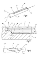
- a laser beam pulse 24 impinges on the surface 26 at the point of impact 25, where it causes a material removal, whereby a funnel-shaped crater 56 is formed, as shown in FIG. 6 is illustrated schematically.
- the point of impact 25 the center or center axis of the crater 56 is designated here.
- a plurality of predetermined, spaced impact locations 25 forms the pulse area 55.
- the control device 29 predefines the deflection device 23 with a pulse path B for arranging successive impact points 25.
- the deflection device 23 directs the laser beam pulses 24 one after the other onto the impact points 25 of the pulse path B.
- the progression of the pulse path B depends on the shape of the pulse surface 55 and follows in the case of the rectangular pulse surface 55 FIG. 3 a meandering course, which is composed of rectilinear sub-courses.
- An impact point 25 in one of the corner points of the pulse surface 55 forms a starting point S, which is spaced from the edge 60 or surface 62 to be produced. Starting from the starting point S, the load steel pulses 24 are placed along the pulse path B up to the impact point 25 in the diagonally opposite corner of the pulse area, which marks the end point E of the pulse path B.
- the tail end section 57 of the pulse path B having the end point E runs parallel to the edge 60 to be produced or parallel to the chip or flank surface 62 adjacent to the edge 60. This tail end section 57 directly adjoins the surface 62 or edge 60 to be produced at.
- a return movement takes place in the deflection device 23 and the laser beam pulses 24 are then again starting at the starting point S on the Pulse train B placed. The return movement is directed away from the contour 60, 62 to be produced. She is in the FIGS. 3 to 5 each illustrated by a dashed arrow.
- the distance A between two successive impact points 25 along the pulse path B is determined by the pulse frequency f of the laser 21 and the adjustment speed of the deflection device 23. When changing direction in the pulse path B, the distance A can also vary.
- the tail end section 57 having the end point E may also run tangentially to the contour 60, 62 to be produced ( FIG. 4 ).
- the pulse path B is spiral.
- the pulse surface 55 may also have the shape of a ring segment ( FIG. 5 ).
- other pulse paths predetermined in the control device 29 can be selected, in which all impact points 25 defining the pulse surface 55 are successively traversed from the starting point S to the end point E.
- the starting point S and the end point E in the direction of the process gas stream P are spaced as far as possible from each other, wherein the process gas flows from the end point E to the starting point S.
- only one laser beam pulse 24 is directed to each impact location 25, while the next laser beam pulse 24 is directed to another impact location 25 of the pulse area 55.
- Such a method is in FIG. 14 in the upper diagram shown.
- the time interval between two successive laser beam pulses 24 results from the reciprocal of the current pulse frequency f of the laser 21.
- the pulsed laser 21 may be designed as a nano-, pico- or Femptose Humanlaser.
- successive laser beam pulses 24 are directed to different points of incidence 25, these laser beam pulses 24 have the intensity I1.
- two or more laser beam pulses 24 can be directed to an impact location 25 before the next impact location 25 is triggered.
- the deflecting device 23 initially directs a pulse train 65 of a plurality of laser beam pulses 24 to an impact point 25 before the subsequent pulse train 65 is directed to another impact point 25.
- the energy which is present in a pulse train 65 and acts on an impact point 25 should correspond to a single laser beam pulse 24 having the intensity I1. Therefore, the intensity I of a single laser beam pulse 24 of a pulse train 65 is reduced.
- the total intensity I of a pulse train 65 is constant. Therefore, the intensity I of a single laser beam pulse 24 in a pulse train 65 corresponds to the quotient of the intensity I1 divided by the number of laser beam pulses 24 contained in the pulse train 65.
- the diameter D of the craters 56 depends on the effective diameter of the laser beam pulses 24 at the point of impingement 25, which can be predetermined via the focusing optics 28 and preferably adjusted and in particular can also be changed during processing.
- a device 66 for Beam homogenization of the pulsed laser beam 22 may be provided.
- the means 66 for steel homogenization causes a more homogeneous energy distribution within the cross-sectional area of the laser beam pulse.
- refractive or diffractive beam homogenizers can be used. It is possible to achieve rectangular intensity profiles with inhomogeneities of less than 2%.
- the pulse edges of the individual laser beam pulses 24 are very steep, as in FIG. 14 is illustrated schematically. At the point of impact 25, a uniform sublimation of the material to be removed is achieved in the area of the laser spot. As a result, the heating of the machined blank 27 during processing can be further reduced.
- FIG. 3 illustrates three process steps for converting a cylindrical blank 27 into a rotary tool having one or more cutting edges 60 and one or more flutes 61.
- a flute 61 is introduced into the blank 27.
- the material is removed in several Abtrags slaughter 59 by the displacement of the pulse surface 55 over the surface of the blank 27 layers, so that the desired Flute 61 forms.
- the size of the pulse area 55 can be varied. This makes it possible to adapt the size of the pulse surface 55 to the desired shape of the chip flute 61 to be produced. For example, in the case of a flute tapering to the groove base 61, the size of the pulse surface 55 can be reduced from one removal layer 59 to the next removal layer 59. By moving along the blank 27 plaster surface 55, the flutes 61 can form almost any. Edges with obtuse or acute angles may be formed in the flute 61.
- FIG. 10 various shapes of flutes 61 are shown schematically.
- the flute 61 can extend parallel to the longitudinal axis L ( FIG. 10 ).
- the flute 61 can also be aligned obliquely to the longitudinal axis L of the cylindrical blank 27.
- the flute 61 extends in a straight line, wherein the edges of the groove with an axis parallel to the longitudinal axis L of the cylindrical blank 27 form an acute angle.
- the flutes 61 can run spirally in the direction of the longitudinal axis L.
- FIG. 13 shown schematically.
- the tool to be produced from the blank 27 has a shaft 62, to which the working area 63 having the flute 61 and the cutting edge 60 adjoins.
- the shaft 62 and the work area 63 may be two different parts connected together.
- the blank 27 may represent a pin that is inserted into a carbide shaft 62.
- the stylus may be a polycrystalline diamond (PCD) or CVD diamond (Chemical Vapor Deposition) diamond tool insert.
- the shank 62 and the working area 63 may also be made of a one-piece piece of material without seams and joints consist.
- the depth of the flute 61 decreases radially measured from the longitudinal axis L.
- the flute 61 may leak towards the flute end 64, for example, ramped.
- the pulse surface 55 is moved several times along the flute 61 to be generated on the blank 27, as in FIG. 12 is shown schematically. With each movement of the pulse surface 55 in a relative direction of movement V, a removal layer 59 is removed. The Abtrags slaughteren 59 are seen radially to the longitudinal axis L above the other.
- the removal of material from the free end 67 of the blank 27 takes place in the direction of the shaft-side flute end 64.
- the direction of movement of the relative movement between the impulse surface 55 and the blank 27 must be reversed.
- the laser beam pulses 24 are turned off.
- the laser beam pulses 24 are first switched on again when the relative direction of movement V has been reversed and between the end 68 of the removed removal layer and the beginning 69 of the current removal layer 59 a displacement dS has been achieved in the direction of the flute profile.
- the amount of displacement dS depends on the desired slope of the outgoing groove bottom in the region of the shaft-side groove end 64.
- the shift dS between the end 68 of a removal layer and the beginning 69 of the subsequent removal layer may depend on the depth of the groove be different in size, if a changing slope of the groove bottom in the region of the shaft side Spannutendes 64 is to be achieved.
- a segment is removed from the original lateral surface of the cylindrical blank 27 radially inward, which constitutes an exemption recess 71. Measured in the radial direction to the longitudinal axis L, the removal depth is constant. The pulse surface 55 is thereby moved several times along the longitudinal axis L of the blank 27. The Abtrags slaughteren are thus one above the other in the radial direction.
- this relief recess 71 may be necessary or expedient to reduce the material removal required in the subsequent manufacture of the cutting edge 60. This can for example be the case with large clearance angle. If the flutes 61 are very large in the circumferential direction or if a sufficient number of flutes 61 are present, the formation of the cut-out recess 71 on the outside 70 can be dispensed with according to the second method step provided here.
- chip guiding steps 75 can be produced in the rake face 73 along the cutting edge 60 in order to improve the chip breakage during machining ( FIG. 18 ).
- a Stützfase 76 is maintained, which is located on the same radius about the longitudinal axis L, as the cutting edge 60 or slightly below.
- the Stauerfase 76 is provided with a microstructure.
- the support bevel on its radial outer surface on a plurality of concave recesses 77, in which can collect cooling lubricant during use of the tool. As a result, frictional forces can be reduced and the service life of the tool can be extended.
- these recesses 77 are oversized schematically illustrated.
- the removal rate per removal layer 62 can be varied over the intensity I of the laser beam pulses 24 during the production of the tool.
- the intensity I during the production of the flute 61 and / or during the generation of the cutout recess 71 can be greater than in the production of the cutting edge 60 and the flank 72.
- the layer thickness of the removal layer 59 changes accordingly.
- Other parameters, such as the relative speed between the pulse surface 55 and the blank 27, may also be differently predetermined in the various method steps, since the requirements for the flatness of an edge profile or a surface are different. In the flute 61 larger bumps can be tolerated, as in the cutting edge 60th
- the positioning device 30 and / or the focusing optics 28 ensure that the focus position for the next removal layer 59 is adjusted again. Because the removal of a material layer, the distance between the surface 26 of the blank 27 and the laser head 19 by the layer thickness of the removed Abtrags Mrs 59 changes. This is compensated at the end of each Abtrags Mrs 59.
- the invention relates to a method and an apparatus for producing a tool from a blank 27, which is in particular a rotary tool which rotates about its longitudinal axis L.
- the rotary tool has at least one cutting edge 60 and a flute 61.
- the rotary tool in its working area 63 is designed to be point-symmetrical with respect to the longitudinal axis L.
- Its working region 63 is produced exclusively by laser ablation with a laser processing machine 20 from a cylindrical blank 27.
- the laser processing machine 20 generates a pulse area 55 with, for example, a rectangular contour via a laser scanner. Within the pulse area 55, the laser beam pulses 24 pass through a predetermined pulse path B having a multiplicity of impact points 25.
Landscapes
- Physics & Mathematics (AREA)
- Optics & Photonics (AREA)
- Engineering & Computer Science (AREA)
- Plasma & Fusion (AREA)
- Mechanical Engineering (AREA)
- Laser Beam Processing (AREA)
Priority Applications (1)
| Application Number | Priority Date | Filing Date | Title |
|---|---|---|---|
| SI201131618T SI2374569T1 (sl) | 2010-03-15 | 2011-03-14 | Laserska obdelovalna naprava in postopek za izdelavo rotacijsko simetričnega orodja |
Applications Claiming Priority (1)
| Application Number | Priority Date | Filing Date | Title |
|---|---|---|---|
| DE102010011508.8A DE102010011508B4 (de) | 2010-03-15 | 2010-03-15 | Verfahren zur Herstellung zumindest einer Spannut und zumindest einer Schneidkante und Laserbearbeitungsvorrichtung |
Publications (3)
| Publication Number | Publication Date |
|---|---|
| EP2374569A2 true EP2374569A2 (fr) | 2011-10-12 |
| EP2374569A3 EP2374569A3 (fr) | 2015-06-03 |
| EP2374569B1 EP2374569B1 (fr) | 2018-11-07 |
Family
ID=44462000
Family Applications (1)
| Application Number | Title | Priority Date | Filing Date |
|---|---|---|---|
| EP11158090.8A Active EP2374569B1 (fr) | 2010-03-15 | 2011-03-14 | Dispositif de traitement au laser et procédé de fabrication d'un outil à rotation symétrique |
Country Status (7)
| Country | Link |
|---|---|
| US (1) | US8872065B2 (fr) |
| EP (1) | EP2374569B1 (fr) |
| JP (1) | JP6087493B2 (fr) |
| CN (1) | CN102189335B (fr) |
| DE (1) | DE102010011508B4 (fr) |
| ES (1) | ES2704907T3 (fr) |
| SI (1) | SI2374569T1 (fr) |
Cited By (5)
| Publication number | Priority date | Publication date | Assignee | Title |
|---|---|---|---|---|
| EP2682219A1 (fr) * | 2012-07-06 | 2014-01-08 | Rollomatic S.A. | Procédé d'usinage d'une pièce |
| WO2019052858A1 (fr) * | 2017-09-15 | 2019-03-21 | Rollomatic S.A. | Dispositif pour l'orientation et le positionnement d'une pièce par rapport à un faisceau laser d'une machine d'usinage au laser |
| EP3677373A4 (fr) * | 2017-08-30 | 2021-05-12 | Roland DG Corporation | Dispositif d'usinage au laser et système d'usinage au laser |
| WO2021205030A1 (fr) | 2020-04-10 | 2021-10-14 | Rolex Sa | Système de tournage laser, procédé de tournage laser utilisant une tel système, et composant obtenu par un tel procédé |
| WO2021205031A1 (fr) | 2020-04-10 | 2021-10-14 | Alphanov | Système de tournage laser, procédé de tournage laser et composant obtenu par l'utilisation d'un tel système |
Families Citing this family (39)
| Publication number | Priority date | Publication date | Assignee | Title |
|---|---|---|---|---|
| US20100126320A1 (en) * | 2008-11-21 | 2010-05-27 | Trumpf, Inc. | Vacuum based part separation |
| DE102011116974A1 (de) | 2011-10-26 | 2013-05-02 | Vollmer Werke Maschinenfabrik Gmbh | Vorrichtung und Verfahren zum Herstellen einer Führungsfase an einem Werkstück, insbesondere an einem schneidenden Werkzeug |
| CN104114316B (zh) * | 2012-02-14 | 2015-11-25 | 村田机械株式会社 | 激光加工机 |
| JP5890739B2 (ja) * | 2012-04-19 | 2016-03-22 | 住友電工ハードメタル株式会社 | 切削工具およびその製造方法 |
| DE102012109245B3 (de) | 2012-09-28 | 2013-11-21 | Jenoptik Automatisierungstechnik Gmbh | Verfahren und Vorrichtung zur Bearbeitung von nicht-rotationssymmetrischen Werkstücken mittels Laserstrahlung |
| RU2494533C1 (ru) * | 2012-11-08 | 2013-09-27 | Открытое акционерное общество "Научно-исследовательский институт "Полюс" им. М.Ф. Стельмаха" | Способ оптической накачки лазера |
| RU2494532C1 (ru) * | 2012-11-08 | 2013-09-27 | Открытое акционерное общество "Научно-исследовательский институт "Полюс" им. М.Ф. Стельмаха" | Генератор импульсов тока |
| DE102012111771B4 (de) | 2012-12-04 | 2020-12-03 | Ewag Ag | Verfahren zur Bearbeitung eines Werkstücks unter Verwendung einer Laserbearbeitungsvorrichtung zur Herstellung eines Schneidwerkzeugs |
| US10252333B2 (en) | 2013-06-11 | 2019-04-09 | Renishaw Plc | Additive manufacturing apparatus and method |
| DE102013217783A1 (de) | 2013-09-05 | 2015-03-05 | Sauer Gmbh Lasertec | Verfahren zur Bearbeitung eines Werkstücks mittels eines Laserstrahls, Laserwerkzeug, Lasermaschine, Maschinensteuerung |
| DE102014109613A1 (de) | 2014-07-09 | 2014-09-04 | Ewag Ag | Verfahren zur Herstellung einer Werkstückfläche an einem stabförmigen Werkstück |
| NO341890B1 (no) * | 2014-08-05 | 2018-02-12 | Aker Solutions As | Posisjonskontrollverktøy for produksjonsrørhenger og en fremgangsmåte |
| CN104526157B (zh) * | 2014-12-25 | 2016-04-20 | 浙江嘉泰激光科技有限公司 | 一种旋转光束预热的激光冲击波微造型加工装置及方法 |
| US11358241B2 (en) | 2015-04-23 | 2022-06-14 | Kennametal Inc. | Cutting tools having microstructured and nanostructured refractory surfaces |
| DE102015212444B4 (de) * | 2015-06-12 | 2025-01-30 | Schuler Pressen Gmbh | Verfahren zur Herstellung einer Blechplatine |
| US10118249B2 (en) * | 2015-10-15 | 2018-11-06 | GM Global Technology Operations LLC | Laser beam welding with a spiral weld path having a first order of continuity |
| DE102016225602B3 (de) | 2016-12-20 | 2018-05-09 | Sauer Gmbh | Verfahren zur Bearbeitung einer Schneidplatte sowie entsprechende Vorrichtung zur Bearbeitung einer Schneidplatte |
| DE102017001785A1 (de) | 2017-02-24 | 2018-08-30 | Stabilus Gmbh | Verfahren zur Fertigung eines Düsenkolbens, Produktionsverfahren für einen Dämpfer, Düsenkolben, Dämpfer, Produktionsanlage zur Produktion eines Dämpfers |
| CN107142372B (zh) * | 2017-04-06 | 2019-01-22 | 广东工业大学 | 针式激光喷丸装置 |
| WO2019093194A1 (fr) * | 2017-11-07 | 2019-05-16 | 住友電工焼結合金株式会社 | Compact fritté à base de fer, son procédé de marquage au laser et son procédé de production |
| US10835990B2 (en) * | 2018-01-26 | 2020-11-17 | Kennametal Inc. | Cutting tools comprising ultrahard materials and methods of making the same |
| DE102018001570A1 (de) * | 2018-02-28 | 2019-08-29 | Vollmer Werke Maschinenfabrik Gmbh | Vorrichtung und Verfahren zum Bearbeiten eines Werkstücks mittels eines Laserstrahls |
| DE102018205585A1 (de) * | 2018-04-12 | 2019-10-17 | Fraunhofer-Gesellschaft zur Förderung der angewandten Forschung e.V. | Verfahren zur Herstellung eines wendelförmigen Gießmodells |
| US11986905B2 (en) | 2018-08-01 | 2024-05-21 | Kyushu University, National University Corporation | Diamond smoothing method |
| DE102018125436A1 (de) * | 2018-10-15 | 2020-04-16 | Ewag Ag | Verfahren zur materialabtragenden Laserbearbeitung eines Werkstücks |
| JP7023214B2 (ja) * | 2018-11-05 | 2022-02-21 | 京セラ株式会社 | 切削工具の製造方法 |
| CN117943695A (zh) | 2019-12-26 | 2024-04-30 | 株式会社尼康 | 加工装置以及加工方法 |
| CN111360415B (zh) * | 2020-03-20 | 2021-03-30 | 吉林大学 | 一种利用化学处理辅助激光加工制备金刚石涡旋光束发生器的方法及其应用 |
| US20230286080A1 (en) * | 2020-05-22 | 2023-09-14 | Bold Laser Automation, Inc. | High velocity vacuum system for laser ablation |
| CN112355543B (zh) * | 2020-10-21 | 2022-04-19 | 中联重科股份有限公司 | 工件的定位装置及加工方法 |
| CN115041816B (zh) * | 2022-05-09 | 2025-11-14 | 中国科学院沈阳自动化研究所 | 一种基于脉冲编码控制的微结构加工装置及方法 |
| TWI831352B (zh) * | 2022-08-31 | 2024-02-01 | 財團法人工業技術研究院 | 雷射微加工裝置 |
| DE102022123237A1 (de) | 2022-09-12 | 2024-03-14 | Rollomatic S.A. | Verfahren zur laserbasierten Bearbeitung eines länglichen Werkstücks und Laserbearbeitungsvorrichtung zur Durchführung des Verfahrens |
| EP4512567A1 (fr) * | 2023-08-24 | 2025-02-26 | Valstybinis Moksliniu Tyrimu Institutas Fiziniu Ir Technologijos Mokslu Centras | Système de formation d'une cavité tridimensionnelle et procédé de formation d'une cavité tridimensionnelle |
| CN117161477B (zh) * | 2023-10-31 | 2024-07-02 | 临沂友诚制锯技术服务有限公司 | 圆弧光路锯齿加工工艺 |
| EP4588602A1 (fr) * | 2024-01-22 | 2025-07-23 | SPT Roth AG | Procédé et appareil pour usiner une ébauche, et capillaire de soudage de fils |
| DE102024110083B4 (de) * | 2024-04-11 | 2025-11-13 | Fraunhofer-Gesellschaft zur Förderung der angewandten Forschung eingetragener Verein | Verfahren und Vorrichtung zur Formkorrektur eines optischen Bauelements mittels Laserstrahlung |
| CN118616894B (zh) * | 2024-08-09 | 2024-12-06 | 长春工程学院 | 一种22MnB5热冲压成形钢激光焊接装置 |
| EP4706866A1 (fr) * | 2024-09-09 | 2026-03-11 | Agathon AG, Maschinenfabrik | Méthode de traitement au laser d'une surface de traitement d'une pièce à usiner |
Citations (3)
| Publication number | Priority date | Publication date | Assignee | Title |
|---|---|---|---|---|
| DE29908585U1 (de) | 1998-12-29 | 1999-09-02 | Laserpluss AG, 55743 Idar-Oberstein | Vorrichtung zur Bearbeitung von Werkstücken aus diamanthaltigen Werkstoffen |
| WO2006038017A2 (fr) | 2004-10-07 | 2006-04-13 | Powerlase Limited | Dispositif de traitement de materiau dur |
| DE102007012815A1 (de) | 2007-03-16 | 2008-09-18 | Sauer Gmbh Lasertec | Verfahren und Vorrichtung zur Werkstückbearbeitung |
Family Cites Families (39)
| Publication number | Priority date | Publication date | Assignee | Title |
|---|---|---|---|---|
| DE2241850C3 (de) | 1972-08-25 | 1978-06-29 | European Rotogravure Association, 8000 Muenchen | Verfahren zur Herstellung von Druckformen mittels eines Energiestrahles |
| LU84687A1 (fr) * | 1983-03-11 | 1984-11-14 | Centre Rech Metallurgique | Procede pour ameliorer l'etat de surface d'un cylindre |
| JPS62218010A (ja) * | 1986-03-19 | 1987-09-25 | Mitsubishi Metal Corp | 超硬ドリル |
| DE8906578U1 (de) | 1989-05-29 | 1990-09-27 | Siemens AG, 1000 Berlin und 8000 München | Laserbearbeitungsvorrichtung |
| DE59002985D1 (de) * | 1989-07-14 | 1993-11-11 | Maho Ag | Verfahren und Vorrichtung zum Herstellen von Hohlräumen in Werkstücken mittels Laserstrahls. |
| DE3923356C1 (fr) * | 1989-07-14 | 1991-02-07 | Maho Ag | |
| EP0577833A4 (en) * | 1991-01-11 | 1994-06-29 | Nippon Steel Corp | Cooling drum for casting thin cast piece; device for and method of forming dimples on peripheral surface of said drum |
| JP3096943B2 (ja) * | 1992-12-07 | 2000-10-10 | 鋼鈑工業株式会社 | ダイヤモンドのレーザ研磨方法および装置ならびにそれを利用したダイヤモンド製品 |
| JPH06304820A (ja) * | 1993-04-23 | 1994-11-01 | Matsushita Electric Works Ltd | 刃物およびその製造方法 |
| DE19544502C1 (de) * | 1995-11-29 | 1997-05-15 | Baasel Scheel Lasergraphics Gm | Lasergravuranlage |
| US5709587A (en) * | 1996-03-25 | 1998-01-20 | Kennametal Inc. | Method and apparatus for honing an elongate rotary tool |
| US6555449B1 (en) * | 1996-05-28 | 2003-04-29 | Trustees Of Columbia University In The City Of New York | Methods for producing uniform large-grained and grain boundary location manipulated polycrystalline thin film semiconductors using sequential lateral solidfication |
| JPH1128900A (ja) * | 1997-05-12 | 1999-02-02 | Sumitomo Heavy Ind Ltd | レーザ光を用いた塗装除去方法及びレーザ処理装置 |
| US7128737B1 (en) * | 1997-10-22 | 2006-10-31 | Carl Zeiss Meditec Ag | Object figuring device |
| DE19900910A1 (de) * | 1999-01-13 | 2000-07-27 | Clean Lasersysteme Gmbh | Vorrichtung und Verfahren zum Behandeln von Oberflächen mittels Laserstrahlung |
| JP2001259869A (ja) * | 2000-03-17 | 2001-09-25 | Toppan Forms Co Ltd | ミシン目形成装置および形成方法 |
| DE10138866B4 (de) * | 2001-08-08 | 2007-05-16 | Bosch Gmbh Robert | Verfahren zum Bohren eines Lochs in ein Werkstück mittels Laserstrahls |
| US6627844B2 (en) * | 2001-11-30 | 2003-09-30 | Matsushita Electric Industrial Co., Ltd. | Method of laser milling |
| US7357486B2 (en) * | 2001-12-20 | 2008-04-15 | Hewlett-Packard Development Company, L.P. | Method of laser machining a fluid slot |
| DE10204993B4 (de) * | 2002-02-05 | 2005-06-09 | Jenoptik Automatisierungstechnik Gmbh | Vorrichtung zum Bearbeiten von dreidimensional ausgedehnten Werkstückoberflächen mittels Laser |
| JP2004009096A (ja) * | 2002-06-06 | 2004-01-15 | Babcock Hitachi Kk | レーザ溶接装置 |
| JP2004223542A (ja) * | 2003-01-21 | 2004-08-12 | Disco Abrasive Syst Ltd | レーザー加工方法およびレーザー加工装置 |
| DE10321123A1 (de) | 2003-05-09 | 2004-11-25 | Lpkf Laser & Electronics Ag | Vorrichtung und Arbeitsverfahren zur Laserbearbeitung |
| JP2004344957A (ja) * | 2003-05-23 | 2004-12-09 | Allied Material Corp | レーザー複合加工機および精密加工製品の製造方法 |
| US7351241B2 (en) | 2003-06-02 | 2008-04-01 | Carl Zeiss Meditec Ag | Method and apparatus for precision working of material |
| DE10352402B4 (de) * | 2003-11-10 | 2015-12-17 | Lasertec Gmbh | Laserbearbeitungsmaschine und Laserbearbeitungsverfahren |
| US7259354B2 (en) | 2004-08-04 | 2007-08-21 | Electro Scientific Industries, Inc. | Methods for processing holes by moving precisely timed laser pulses in circular and spiral trajectories |
| DE102006005401A1 (de) * | 2006-02-03 | 2007-08-09 | Gesau-Werkzeuge Fabrikations- Und Service Gmbh | Verfahren zur Herstellung eines Schaftfräsers |
| JP2007216327A (ja) * | 2006-02-15 | 2007-08-30 | Aisin Seiki Co Ltd | チップブレーカの形成方法 |
| DE102006017629A1 (de) | 2006-02-22 | 2007-08-30 | Lpkf Laser & Electronics Ag | Verfahren und Vorrichtung zur Laserbearbeitung |
| US20070231541A1 (en) * | 2006-03-31 | 2007-10-04 | 3M Innovative Properties Company | Microstructured tool and method of making same using laser ablation |
| US8168917B2 (en) * | 2006-05-30 | 2012-05-01 | Caterpillar Inc. | System and method for laser-encoding information on hydraulic rods |
| WO2008110613A1 (fr) * | 2007-03-13 | 2008-09-18 | Laser- Und Medizin-Technologie Gmbh Berlin | Dispositif et procédé pour guider un rayon lumineux |
| DE102007014933A1 (de) | 2007-03-22 | 2008-09-25 | Laser- Und Medizin-Technologie Gmbh, Berlin | Verfahren und Vorrichtung zur schnellen Ablenkung eines Lichtstrahles auf eine einstellbare Längsbahn |
| DE102007012816B4 (de) * | 2007-03-16 | 2009-12-03 | Sauer Gmbh Lasertec | Verfahren und Vorrichtung zur Werkstückbearbeitung |
| WO2009137494A1 (fr) * | 2008-05-05 | 2009-11-12 | Applied Spectra, Inc. | Appareil et procédé d’ablation au laser |
| JP2009297745A (ja) * | 2008-06-13 | 2009-12-24 | Panasonic Corp | 金型の加工方法 |
| CN201405164Y (zh) * | 2009-04-30 | 2010-02-17 | 苏州德龙激光有限公司 | 新型双光路绿光微孔加工装置 |
| DE102009044316B4 (de) * | 2009-10-22 | 2015-04-30 | Ewag Ag | Verfahren zur Herstellung einer Fläche und/oder einer Kante an einem Rohling sowie Laserbearbeitungsvorrichtung zur Durchführung des Verfahrens |
-
2010
- 2010-03-15 DE DE102010011508.8A patent/DE102010011508B4/de not_active Expired - Fee Related
-
2011
- 2011-03-11 US US13/065,041 patent/US8872065B2/en active Active
- 2011-03-14 SI SI201131618T patent/SI2374569T1/sl unknown
- 2011-03-14 CN CN201110108541.2A patent/CN102189335B/zh active Active
- 2011-03-14 JP JP2011055564A patent/JP6087493B2/ja active Active
- 2011-03-14 ES ES11158090T patent/ES2704907T3/es active Active
- 2011-03-14 EP EP11158090.8A patent/EP2374569B1/fr active Active
Patent Citations (3)
| Publication number | Priority date | Publication date | Assignee | Title |
|---|---|---|---|---|
| DE29908585U1 (de) | 1998-12-29 | 1999-09-02 | Laserpluss AG, 55743 Idar-Oberstein | Vorrichtung zur Bearbeitung von Werkstücken aus diamanthaltigen Werkstoffen |
| WO2006038017A2 (fr) | 2004-10-07 | 2006-04-13 | Powerlase Limited | Dispositif de traitement de materiau dur |
| DE102007012815A1 (de) | 2007-03-16 | 2008-09-18 | Sauer Gmbh Lasertec | Verfahren und Vorrichtung zur Werkstückbearbeitung |
Cited By (9)
| Publication number | Priority date | Publication date | Assignee | Title |
|---|---|---|---|---|
| EP2682219A1 (fr) * | 2012-07-06 | 2014-01-08 | Rollomatic S.A. | Procédé d'usinage d'une pièce |
| EP2700471A1 (fr) * | 2012-07-06 | 2014-02-26 | Rollomatic S.A. | Procédé d'usinage d'une pièce |
| EP3677373A4 (fr) * | 2017-08-30 | 2021-05-12 | Roland DG Corporation | Dispositif d'usinage au laser et système d'usinage au laser |
| WO2019052858A1 (fr) * | 2017-09-15 | 2019-03-21 | Rollomatic S.A. | Dispositif pour l'orientation et le positionnement d'une pièce par rapport à un faisceau laser d'une machine d'usinage au laser |
| CN111032279A (zh) * | 2017-09-15 | 2020-04-17 | 瑞士路劳曼迪有限公司 | 用于相对于激光加工机的激光束定向和定位工件的装置 |
| CN111032279B (zh) * | 2017-09-15 | 2021-09-17 | 瑞士路劳曼迪有限公司 | 用于相对于激光加工机的激光束定向和定位工件的装置 |
| US11872653B2 (en) | 2017-09-15 | 2024-01-16 | Rollomatic S.A. | Device for aligning and positioning a workpiece relative to a laser beam of a laser processing machine |
| WO2021205030A1 (fr) | 2020-04-10 | 2021-10-14 | Rolex Sa | Système de tournage laser, procédé de tournage laser utilisant une tel système, et composant obtenu par un tel procédé |
| WO2021205031A1 (fr) | 2020-04-10 | 2021-10-14 | Alphanov | Système de tournage laser, procédé de tournage laser et composant obtenu par l'utilisation d'un tel système |
Also Published As
| Publication number | Publication date |
|---|---|
| CN102189335A (zh) | 2011-09-21 |
| EP2374569B1 (fr) | 2018-11-07 |
| CN102189335B (zh) | 2016-03-16 |
| DE102010011508A1 (de) | 2011-09-15 |
| DE102010011508B4 (de) | 2015-12-10 |
| JP6087493B2 (ja) | 2017-03-01 |
| ES2704907T3 (es) | 2019-03-20 |
| JP2011200935A (ja) | 2011-10-13 |
| US20110220625A1 (en) | 2011-09-15 |
| SI2374569T1 (sl) | 2019-01-31 |
| EP2374569A3 (fr) | 2015-06-03 |
| US8872065B2 (en) | 2014-10-28 |
Similar Documents
| Publication | Publication Date | Title |
|---|---|---|
| EP2374569B1 (fr) | Dispositif de traitement au laser et procédé de fabrication d'un outil à rotation symétrique | |
| DE102009044316B4 (de) | Verfahren zur Herstellung einer Fläche und/oder einer Kante an einem Rohling sowie Laserbearbeitungsvorrichtung zur Durchführung des Verfahrens | |
| EP0407969B1 (fr) | Procédé et dispositif pour réaliser des espaces creux dans les pièces à usiner au moyen d'un faisceau laser | |
| EP3166747B1 (fr) | Procédé de production d'une surface sur une pièce en forme de barre | |
| EP1516068B1 (fr) | Procede pour lisser et polir des surfaces par traitement avec un rayonnement energetique | |
| EP2489458B1 (fr) | Dispositif de traitement laser doté d'un agencement laser commutable et procédé de traitement laser | |
| EP2691206B1 (fr) | Procédé d'usinage par faisceau laser d'une pièce | |
| EP4035823B1 (fr) | Procédé d'usinage par faisceau d'une pièce tabulaire ou tubulaire | |
| EP3256285A1 (fr) | Dispositif d'irradiation, machine de traitement et procédé de fabrication d'une couche ou d'une sous-zone d'une couche d'une pièce tridimensionnelle | |
| EP4238687B1 (fr) | Procédé d'usinage d'une pièce à usiner en forme de plaque ou de tube | |
| DE102012003202A1 (de) | Vorrichtung und Verfahren zum Bearbeiten von Werkstücken, insbesondere von Schneiden oder mit Schneiden versehenen Werkstücken, mit einem Nasslaser | |
| DE102005027800A1 (de) | Vorrichtung zum mehrfachen Trennen eines flachen Werkstückes aus einem spröden Material mittels Laser | |
| EP3414044B1 (fr) | Procédé de production d'une partie d'une couche d'un composant tridimensionnel | |
| EP4238690B1 (fr) | Procédé d'usinage d'une pièce en forme de plaque ou de tube | |
| DE102012217766B4 (de) | Verfahren und Vorrichtung zum Dampfdruck-Abtragschneiden eines metallischen Werkstücks | |
| DE102012017130B4 (de) | Laser-Rohreinschweißen | |
| WO2023072568A1 (fr) | Procédé de fabrication de parties de pièces présentant des arêtes de coupe chanfreinées | |
| DE102009047995B3 (de) | Verfahren zur gratfreien trennenden Bearbeitung von Werkstücken | |
| DE29908585U1 (de) | Vorrichtung zur Bearbeitung von Werkstücken aus diamanthaltigen Werkstoffen | |
| EP4251091A1 (fr) | Outil d'enlèvement de copeaux pour traitement dentaire, en particulier lime endodontique, et procédé de fabrication d'un outil d'enlèvement de copeaux | |
| EP2841230B1 (fr) | Procédé et dispositif pour usiner une pièce cylindrique | |
| DE102022123237A1 (de) | Verfahren zur laserbasierten Bearbeitung eines länglichen Werkstücks und Laserbearbeitungsvorrichtung zur Durchführung des Verfahrens | |
| DE102024120693A1 (de) | Laserschneiddüse sowie Verfahren zum Laserschneiden unter Verwendung einer Laserschneiddüse |
Legal Events
| Date | Code | Title | Description |
|---|---|---|---|
| PUAI | Public reference made under article 153(3) epc to a published international application that has entered the european phase |
Free format text: ORIGINAL CODE: 0009012 |
|
| AK | Designated contracting states |
Kind code of ref document: A2 Designated state(s): AL AT BE BG CH CY CZ DE DK EE ES FI FR GB GR HR HU IE IS IT LI LT LU LV MC MK MT NL NO PL PT RO RS SE SI SK SM TR |
|
| AX | Request for extension of the european patent |
Extension state: BA ME |
|
| PUAL | Search report despatched |
Free format text: ORIGINAL CODE: 0009013 |
|
| AK | Designated contracting states |
Kind code of ref document: A3 Designated state(s): AL AT BE BG CH CY CZ DE DK EE ES FI FR GB GR HR HU IE IS IT LI LT LU LV MC MK MT NL NO PL PT RO RS SE SI SK SM TR |
|
| AX | Request for extension of the european patent |
Extension state: BA ME |
|
| RIC1 | Information provided on ipc code assigned before grant |
Ipc: B23K 26/36 20140101ALI20150428BHEP Ipc: B23K 26/06 20140101ALI20150428BHEP Ipc: B23K 26/08 20140101AFI20150428BHEP |
|
| 17P | Request for examination filed |
Effective date: 20151110 |
|
| RBV | Designated contracting states (corrected) |
Designated state(s): AL AT BE BG CH CY CZ DE DK EE ES FI FR GB GR HR HU IE IS IT LI LT LU LV MC MK MT NL NO PL PT RO RS SE SI SK SM TR |
|
| RIC1 | Information provided on ipc code assigned before grant |
Ipc: B23K 26/08 20060101AFI20180607BHEP Ipc: B23K 26/06 20060101ALI20180607BHEP Ipc: B23K 26/36 20060101ALI20180607BHEP |
|
| GRAP | Despatch of communication of intention to grant a patent |
Free format text: ORIGINAL CODE: EPIDOSNIGR1 |
|
| STAA | Information on the status of an ep patent application or granted ep patent |
Free format text: STATUS: GRANT OF PATENT IS INTENDED |
|
| INTG | Intention to grant announced |
Effective date: 20180724 |
|
| GRAS | Grant fee paid |
Free format text: ORIGINAL CODE: EPIDOSNIGR3 |
|
| GRAA | (expected) grant |
Free format text: ORIGINAL CODE: 0009210 |
|
| STAA | Information on the status of an ep patent application or granted ep patent |
Free format text: STATUS: THE PATENT HAS BEEN GRANTED |
|
| AK | Designated contracting states |
Kind code of ref document: B1 Designated state(s): AL AT BE BG CH CY CZ DE DK EE ES FI FR GB GR HR HU IE IS IT LI LT LU LV MC MK MT NL NO PL PT RO RS SE SI SK SM TR |
|
| REG | Reference to a national code |
Ref country code: GB Ref legal event code: FG4D Free format text: NOT ENGLISH |
|
| REG | Reference to a national code |
Ref country code: CH Ref legal event code: EP Ref country code: AT Ref legal event code: REF Ref document number: 1061489 Country of ref document: AT Kind code of ref document: T Effective date: 20181115 |
|
| REG | Reference to a national code |
Ref country code: DE Ref legal event code: R096 Ref document number: 502011014955 Country of ref document: DE |
|
| REG | Reference to a national code |
Ref country code: IE Ref legal event code: FG4D Free format text: LANGUAGE OF EP DOCUMENT: GERMAN |
|
| REG | Reference to a national code |
Ref country code: CH Ref legal event code: NV Representative=s name: VALIPAT S.A. GEVERS SA, CH |
|
| REG | Reference to a national code |
Ref country code: NL Ref legal event code: FP |
|
| REG | Reference to a national code |
Ref country code: SE Ref legal event code: TRGR |
|
| REG | Reference to a national code |
Ref country code: ES Ref legal event code: FG2A Ref document number: 2704907 Country of ref document: ES Kind code of ref document: T3 Effective date: 20190320 |
|
| REG | Reference to a national code |
Ref country code: LT Ref legal event code: MG4D |
|
| REG | Reference to a national code |
Ref country code: CH Ref legal event code: PCAR Free format text: NEW ADDRESS: RUE DES NOYERS 11, 2000 NEUCHATEL (CH) |
|
| PG25 | Lapsed in a contracting state [announced via postgrant information from national office to epo] |
Ref country code: FI Free format text: LAPSE BECAUSE OF FAILURE TO SUBMIT A TRANSLATION OF THE DESCRIPTION OR TO PAY THE FEE WITHIN THE PRESCRIBED TIME-LIMIT Effective date: 20181107 Ref country code: LV Free format text: LAPSE BECAUSE OF FAILURE TO SUBMIT A TRANSLATION OF THE DESCRIPTION OR TO PAY THE FEE WITHIN THE PRESCRIBED TIME-LIMIT Effective date: 20181107 Ref country code: HR Free format text: LAPSE BECAUSE OF FAILURE TO SUBMIT A TRANSLATION OF THE DESCRIPTION OR TO PAY THE FEE WITHIN THE PRESCRIBED TIME-LIMIT Effective date: 20181107 Ref country code: LT Free format text: LAPSE BECAUSE OF FAILURE TO SUBMIT A TRANSLATION OF THE DESCRIPTION OR TO PAY THE FEE WITHIN THE PRESCRIBED TIME-LIMIT Effective date: 20181107 Ref country code: BG Free format text: LAPSE BECAUSE OF FAILURE TO SUBMIT A TRANSLATION OF THE DESCRIPTION OR TO PAY THE FEE WITHIN THE PRESCRIBED TIME-LIMIT Effective date: 20190207 Ref country code: NO Free format text: LAPSE BECAUSE OF FAILURE TO SUBMIT A TRANSLATION OF THE DESCRIPTION OR TO PAY THE FEE WITHIN THE PRESCRIBED TIME-LIMIT Effective date: 20190207 Ref country code: IS Free format text: LAPSE BECAUSE OF FAILURE TO SUBMIT A TRANSLATION OF THE DESCRIPTION OR TO PAY THE FEE WITHIN THE PRESCRIBED TIME-LIMIT Effective date: 20190307 |
|
| PG25 | Lapsed in a contracting state [announced via postgrant information from national office to epo] |
Ref country code: PT Free format text: LAPSE BECAUSE OF FAILURE TO SUBMIT A TRANSLATION OF THE DESCRIPTION OR TO PAY THE FEE WITHIN THE PRESCRIBED TIME-LIMIT Effective date: 20190307 Ref country code: GR Free format text: LAPSE BECAUSE OF FAILURE TO SUBMIT A TRANSLATION OF THE DESCRIPTION OR TO PAY THE FEE WITHIN THE PRESCRIBED TIME-LIMIT Effective date: 20190208 Ref country code: RS Free format text: LAPSE BECAUSE OF FAILURE TO SUBMIT A TRANSLATION OF THE DESCRIPTION OR TO PAY THE FEE WITHIN THE PRESCRIBED TIME-LIMIT Effective date: 20181107 Ref country code: AL Free format text: LAPSE BECAUSE OF FAILURE TO SUBMIT A TRANSLATION OF THE DESCRIPTION OR TO PAY THE FEE WITHIN THE PRESCRIBED TIME-LIMIT Effective date: 20181107 |
|
| PG25 | Lapsed in a contracting state [announced via postgrant information from national office to epo] |
Ref country code: PL Free format text: LAPSE BECAUSE OF FAILURE TO SUBMIT A TRANSLATION OF THE DESCRIPTION OR TO PAY THE FEE WITHIN THE PRESCRIBED TIME-LIMIT Effective date: 20181107 Ref country code: DK Free format text: LAPSE BECAUSE OF FAILURE TO SUBMIT A TRANSLATION OF THE DESCRIPTION OR TO PAY THE FEE WITHIN THE PRESCRIBED TIME-LIMIT Effective date: 20181107 |
|
| REG | Reference to a national code |
Ref country code: DE Ref legal event code: R026 Ref document number: 502011014955 Country of ref document: DE |
|
| PLBI | Opposition filed |
Free format text: ORIGINAL CODE: 0009260 |
|
| PLAX | Notice of opposition and request to file observation + time limit sent |
Free format text: ORIGINAL CODE: EPIDOSNOBS2 |
|
| PG25 | Lapsed in a contracting state [announced via postgrant information from national office to epo] |
Ref country code: EE Free format text: LAPSE BECAUSE OF FAILURE TO SUBMIT A TRANSLATION OF THE DESCRIPTION OR TO PAY THE FEE WITHIN THE PRESCRIBED TIME-LIMIT Effective date: 20181107 Ref country code: SM Free format text: LAPSE BECAUSE OF FAILURE TO SUBMIT A TRANSLATION OF THE DESCRIPTION OR TO PAY THE FEE WITHIN THE PRESCRIBED TIME-LIMIT Effective date: 20181107 Ref country code: SK Free format text: LAPSE BECAUSE OF FAILURE TO SUBMIT A TRANSLATION OF THE DESCRIPTION OR TO PAY THE FEE WITHIN THE PRESCRIBED TIME-LIMIT Effective date: 20181107 Ref country code: RO Free format text: LAPSE BECAUSE OF FAILURE TO SUBMIT A TRANSLATION OF THE DESCRIPTION OR TO PAY THE FEE WITHIN THE PRESCRIBED TIME-LIMIT Effective date: 20181107 |
|
| 26 | Opposition filed |
Opponent name: VOLLMER WERKE MASCHINENFABRIK GMBH Effective date: 20190807 |
|
| PG25 | Lapsed in a contracting state [announced via postgrant information from national office to epo] |
Ref country code: MC Free format text: LAPSE BECAUSE OF FAILURE TO SUBMIT A TRANSLATION OF THE DESCRIPTION OR TO PAY THE FEE WITHIN THE PRESCRIBED TIME-LIMIT Effective date: 20181107 |
|
| PG25 | Lapsed in a contracting state [announced via postgrant information from national office to epo] |
Ref country code: LU Free format text: LAPSE BECAUSE OF NON-PAYMENT OF DUE FEES Effective date: 20190314 |
|
| REG | Reference to a national code |
Ref country code: BE Ref legal event code: MM Effective date: 20190331 |
|
| PLBB | Reply of patent proprietor to notice(s) of opposition received |
Free format text: ORIGINAL CODE: EPIDOSNOBS3 |
|
| PG25 | Lapsed in a contracting state [announced via postgrant information from national office to epo] |
Ref country code: IE Free format text: LAPSE BECAUSE OF NON-PAYMENT OF DUE FEES Effective date: 20190314 |
|
| PG25 | Lapsed in a contracting state [announced via postgrant information from national office to epo] |
Ref country code: BE Free format text: LAPSE BECAUSE OF NON-PAYMENT OF DUE FEES Effective date: 20190331 |
|
| PG25 | Lapsed in a contracting state [announced via postgrant information from national office to epo] |
Ref country code: TR Free format text: LAPSE BECAUSE OF FAILURE TO SUBMIT A TRANSLATION OF THE DESCRIPTION OR TO PAY THE FEE WITHIN THE PRESCRIBED TIME-LIMIT Effective date: 20181107 |
|
| PG25 | Lapsed in a contracting state [announced via postgrant information from national office to epo] |
Ref country code: MT Free format text: LAPSE BECAUSE OF FAILURE TO SUBMIT A TRANSLATION OF THE DESCRIPTION OR TO PAY THE FEE WITHIN THE PRESCRIBED TIME-LIMIT Effective date: 20181107 |
|
| RAP2 | Party data changed (patent owner data changed or rights of a patent transferred) |
Owner name: FRITZ STUDER AG |
|
| PG25 | Lapsed in a contracting state [announced via postgrant information from national office to epo] |
Ref country code: CY Free format text: LAPSE BECAUSE OF FAILURE TO SUBMIT A TRANSLATION OF THE DESCRIPTION OR TO PAY THE FEE WITHIN THE PRESCRIBED TIME-LIMIT Effective date: 20181107 |
|
| PG25 | Lapsed in a contracting state [announced via postgrant information from national office to epo] |
Ref country code: HU Free format text: LAPSE BECAUSE OF FAILURE TO SUBMIT A TRANSLATION OF THE DESCRIPTION OR TO PAY THE FEE WITHIN THE PRESCRIBED TIME-LIMIT; INVALID AB INITIO Effective date: 20110314 |
|
| PLAB | Opposition data, opponent's data or that of the opponent's representative modified |
Free format text: ORIGINAL CODE: 0009299OPPO |
|
| R26 | Opposition filed (corrected) |
Opponent name: VOLLMER WERKE MASCHINENFABRIK GMBH Effective date: 20190807 |
|
| PLCK | Communication despatched that opposition was rejected |
Free format text: ORIGINAL CODE: EPIDOSNREJ1 |
|
| APBM | Appeal reference recorded |
Free format text: ORIGINAL CODE: EPIDOSNREFNO |
|
| APBP | Date of receipt of notice of appeal recorded |
Free format text: ORIGINAL CODE: EPIDOSNNOA2O |
|
| APAH | Appeal reference modified |
Free format text: ORIGINAL CODE: EPIDOSCREFNO |
|
| REG | Reference to a national code |
Ref country code: DE Ref legal event code: R100 Ref document number: 502011014955 Country of ref document: DE |
|
| APBU | Appeal procedure closed |
Free format text: ORIGINAL CODE: EPIDOSNNOA9O |
|
| PLBN | Opposition rejected |
Free format text: ORIGINAL CODE: 0009273 |
|
| STAA | Information on the status of an ep patent application or granted ep patent |
Free format text: STATUS: OPPOSITION REJECTED |
|
| 27O | Opposition rejected |
Effective date: 20220428 |
|
| PG25 | Lapsed in a contracting state [announced via postgrant information from national office to epo] |
Ref country code: MK Free format text: LAPSE BECAUSE OF FAILURE TO SUBMIT A TRANSLATION OF THE DESCRIPTION OR TO PAY THE FEE WITHIN THE PRESCRIBED TIME-LIMIT Effective date: 20181107 |
|
| REG | Reference to a national code |
Ref country code: DE Ref legal event code: R081 Ref document number: 502011014955 Country of ref document: DE Owner name: FRITZ STUDER AG, CH Free format text: FORMER OWNER: EWAG AG, ETZIKEN, CH Ref country code: DE Ref legal event code: R081 Ref document number: 502011014955 Country of ref document: DE Owner name: WALTER MASCHINENBAU GMBH, DE Free format text: FORMER OWNER: EWAG AG, ETZIKEN, CH |
|
| PGFP | Annual fee paid to national office [announced via postgrant information from national office to epo] |
Ref country code: FR Payment date: 20230322 Year of fee payment: 13 Ref country code: AT Payment date: 20230322 Year of fee payment: 13 |
|
| PGFP | Annual fee paid to national office [announced via postgrant information from national office to epo] |
Ref country code: SI Payment date: 20230302 Year of fee payment: 13 Ref country code: GB Payment date: 20230321 Year of fee payment: 13 |
|
| PGFP | Annual fee paid to national office [announced via postgrant information from national office to epo] |
Ref country code: NL Payment date: 20230321 Year of fee payment: 13 |
|
| PGFP | Annual fee paid to national office [announced via postgrant information from national office to epo] |
Ref country code: ES Payment date: 20230529 Year of fee payment: 13 |
|
| REG | Reference to a national code |
Ref country code: DE Ref legal event code: R081 Ref document number: 502011014955 Country of ref document: DE Owner name: WALTER MASCHINENBAU GMBH, DE Free format text: FORMER OWNER: FRITZ STUDER AG, STEFFISBURG, CH |
|
| REG | Reference to a national code |
Ref country code: NL Ref legal event code: MM Effective date: 20240401 |
|
| REG | Reference to a national code |
Ref country code: AT Ref legal event code: MM01 Ref document number: 1061489 Country of ref document: AT Kind code of ref document: T Effective date: 20240314 |
|
| GBPC | Gb: european patent ceased through non-payment of renewal fee |
Effective date: 20240314 |
|
| PG25 | Lapsed in a contracting state [announced via postgrant information from national office to epo] |
Ref country code: NL Free format text: LAPSE BECAUSE OF NON-PAYMENT OF DUE FEES Effective date: 20240401 |
|
| PG25 | Lapsed in a contracting state [announced via postgrant information from national office to epo] |
Ref country code: NL Free format text: LAPSE BECAUSE OF NON-PAYMENT OF DUE FEES Effective date: 20240401 |
|
| PG25 | Lapsed in a contracting state [announced via postgrant information from national office to epo] |
Ref country code: GB Free format text: LAPSE BECAUSE OF NON-PAYMENT OF DUE FEES Effective date: 20240314 |
|
| PG25 | Lapsed in a contracting state [announced via postgrant information from national office to epo] |
Ref country code: FR Free format text: LAPSE BECAUSE OF NON-PAYMENT OF DUE FEES Effective date: 20240331 |
|
| PG25 | Lapsed in a contracting state [announced via postgrant information from national office to epo] |
Ref country code: AT Free format text: LAPSE BECAUSE OF NON-PAYMENT OF DUE FEES Effective date: 20240314 |
|
| PG25 | Lapsed in a contracting state [announced via postgrant information from national office to epo] |
Ref country code: GB Free format text: LAPSE BECAUSE OF NON-PAYMENT OF DUE FEES Effective date: 20240314 Ref country code: FR Free format text: LAPSE BECAUSE OF NON-PAYMENT OF DUE FEES Effective date: 20240331 Ref country code: AT Free format text: LAPSE BECAUSE OF NON-PAYMENT OF DUE FEES Effective date: 20240314 |
|
| PGFP | Annual fee paid to national office [announced via postgrant information from national office to epo] |
Ref country code: DE Payment date: 20250226 Year of fee payment: 15 |
|
| PG25 | Lapsed in a contracting state [announced via postgrant information from national office to epo] |
Ref country code: ES Free format text: LAPSE BECAUSE OF NON-PAYMENT OF DUE FEES Effective date: 20240315 |
|
| PGFP | Annual fee paid to national office [announced via postgrant information from national office to epo] |
Ref country code: CH Payment date: 20250401 Year of fee payment: 15 |
|
| REG | Reference to a national code |
Ref country code: SI Ref legal event code: KO00 Effective date: 20240315 |
|
| PGFP | Annual fee paid to national office [announced via postgrant information from national office to epo] |
Ref country code: SE Payment date: 20260319 Year of fee payment: 16 |
|
| PGFP | Annual fee paid to national office [announced via postgrant information from national office to epo] |
Ref country code: IT Payment date: 20260324 Year of fee payment: 16 |
|
| REG | Reference to a national code |
Ref country code: CH Ref legal event code: U11 Free format text: ST27 STATUS EVENT CODE: U-0-0-U10-U11 (AS PROVIDED BY THE NATIONAL OFFICE) Effective date: 20260421 |
|
| PGFP | Annual fee paid to national office [announced via postgrant information from national office to epo] |
Ref country code: CZ Payment date: 20260310 Year of fee payment: 16 |