EP2374724A1 - Clip de fermeture et moule pour fermer ce clip - Google Patents
Clip de fermeture et moule pour fermer ce clip Download PDFInfo
- Publication number
- EP2374724A1 EP2374724A1 EP10003830A EP10003830A EP2374724A1 EP 2374724 A1 EP2374724 A1 EP 2374724A1 EP 10003830 A EP10003830 A EP 10003830A EP 10003830 A EP10003830 A EP 10003830A EP 2374724 A1 EP2374724 A1 EP 2374724A1
- Authority
- EP
- European Patent Office
- Prior art keywords
- closure clip
- arms
- arbor
- die
- closure
- Prior art date
- Legal status (The legal status is an assumption and is not a legal conclusion. Google has not performed a legal analysis and makes no representation as to the accuracy of the status listed.)
- Granted
Links
Images



Classifications
-
- B—PERFORMING OPERATIONS; TRANSPORTING
- B65—CONVEYING; PACKING; STORING; HANDLING THIN OR FILAMENTARY MATERIAL
- B65B—MACHINES, APPARATUS OR DEVICES FOR, OR METHODS OF, PACKAGING ARTICLES OR MATERIALS; UNPACKING
- B65B67/00—Apparatus or devices facilitating manual packaging operations; Sack holders
- B65B67/02—Packaging of articles or materials in containers
- B65B67/06—Manually-operable devices for closing bag necks, by applying and securing lengths of string, wire or tape
-
- B—PERFORMING OPERATIONS; TRANSPORTING
- B65—CONVEYING; PACKING; STORING; HANDLING THIN OR FILAMENTARY MATERIAL
- B65B—MACHINES, APPARATUS OR DEVICES FOR, OR METHODS OF, PACKAGING ARTICLES OR MATERIALS; UNPACKING
- B65B51/00—Devices for, or methods of, sealing or securing package folds or closures; Devices for gathering or twisting wrappers, or necks of bags
- B65B51/04—Applying separate sealing or securing members, e.g. clips
- B65B51/043—Applying springy clips around bag necks
-
- B—PERFORMING OPERATIONS; TRANSPORTING
- B65—CONVEYING; PACKING; STORING; HANDLING THIN OR FILAMENTARY MATERIAL
- B65D—CONTAINERS FOR STORAGE OR TRANSPORT OF ARTICLES OR MATERIALS, e.g. BAGS, BARRELS, BOTTLES, BOXES, CANS, CARTONS, CRATES, DRUMS, JARS, TANKS, HOPPERS, FORWARDING CONTAINERS; ACCESSORIES, CLOSURES, OR FITTINGS THEREFOR; PACKAGING ELEMENTS; PACKAGES
- B65D33/00—Details of, or accessories for, sacks or bags
- B65D33/16—End- or aperture-closing arrangements or devices
- B65D33/1616—Elements constricting the neck of the bag
- B65D33/1641—Staples, clips or clamps made of metal
-
- Y—GENERAL TAGGING OF NEW TECHNOLOGICAL DEVELOPMENTS; GENERAL TAGGING OF CROSS-SECTIONAL TECHNOLOGIES SPANNING OVER SEVERAL SECTIONS OF THE IPC; TECHNICAL SUBJECTS COVERED BY FORMER USPC CROSS-REFERENCE ART COLLECTIONS [XRACs] AND DIGESTS
- Y10—TECHNICAL SUBJECTS COVERED BY FORMER USPC
- Y10T—TECHNICAL SUBJECTS COVERED BY FORMER US CLASSIFICATION
- Y10T24/00—Buckles, buttons, clasps, etc.
- Y10T24/15—Bag fasteners
- Y10T24/158—Slides to lock bag end within housing
Definitions
- the present invention relates to a closure clip and a die for closing said closure clip according to the preamble of independent claims 1 and 12.
- the present invention relates to a closure clip for closing tubular or bag-shaped packing casing for packing loosely goods or foodstuff, like fruit or vegetables.
- the closure clip comprises two arms extending at least substantially in a plane and at least substantially parallel to each other, having first and second ends and inner and outer surfaces facing from the arms and a bottom portion arranged in the plane defined by the two arms, having an inner and an outer surface and connecting the two arms by their first ends, thereby forming a substantially U-shaped closure clip.
- the present invention further relates to a die closing a closure clip.
- the die has an approximately cuboid die body including a first, horizontal top surface, a second, vertical front surface and a third, vertical side surface, and an approximately semicircular recess extending from the center of the horizontal top surface into the die body.
- the die further comprises two guide channels for guiding the second ends of the closure clip, the guide channels are arranged in the surface of the semicircular recess parallel to each.
- said goods For storing and/or transporting loosely goods or foodstuff, like fruit or vegetables, said goods may be packed in a tubular or bag-shaped packing casing.
- Said tubular or bag-shaped casing may be made of e.g. web-like material. While packing, a predetermined portion or number of said goods is filled into the bag-shaped casing or a tubular casing portion closed at one end.
- Clipping machines are used for packing said goods into respective packing casings, in particular, for applying closure means, like substantially U-shaped closure clips, to said packing casing for closing the packing casing. Additionally, loops for pendulous storing said packed goods, wrist straps and/or labels may be attached to the packing casing by means of the closure clip.
- a generally known clipping machine for closing said packing casing and for attaching a loop or the like to the packing casing comprises, amongst others, displacer elements for gathering the filled tubular or bag-shaped packing casing and for providing a plait-like portion, and a punch and die assembly for attaching the closure clip to the plait-like portion and for closing said clip around said plait-like portion.
- a clip is conveyed to the plait-like portion, positioned around the plait-like portion and closed by bending the arms of the U-shaped closure clip around the plait-like portion.
- said clip is pressed by the punch pushing the clip toward the die, with the tips of its arms against the die.
- the die comprises guide channels for guiding the arms of the clip along each other while being bent around the plait-like portion.
- a substantially U-shaped closure clip for closing bags or film tubes having a bottom portion and two arms coupled to said bottom portion. At the free ends of each of the two arms, latch elements are arranged for fixedly connecting the free ends of the arms, when the closure clip is in the closed configuration, thereby the closure clip forms a closed ring. At the inner surface of the bottom portion and the arms, teeth project inwards the closure clip. In the closed configuration, said teeth engaging the bag or film tube material to prevent the closure clip from slipping off the bag or film tube material.
- the closure clips may be coupled to each other for forming a chain which may be stored on a clip supply, like a reel.
- the device for closing said closure clip comprises a die and punch assembly.
- the die is formed by a solid body including a recess. Said recess has tapering side surfaces for guiding the free ends of the closure clip towards each other and for coupling the free ends of the arms by the latch elements.
- the punch for pushing the closure clip toward the die has a lower surface directed towards the bottom portion of the closure clip. Said lower surface matches the outer surface of the bottom portion of the closure clip.
- a closure clip for closing tubular or bag-shaped packing casing for packing loosely goods or foodstuff, like fruit or vegetables.
- the closure clip comprises two arms extending at least substantially in a plane and at least substantially parallel to each other, having first and second ends and inner and outer surfaces facing from the arms and a bottom portion arranged in the plane defined by the two arms, having an inner and an outer surface and connecting the two arms by their first ends, thereby forming a substantially U-shaped closure clip.
- the closure clip has at least one arbor having a first end and a second end, extending from the inner surface of the bottom portion, to which the arbor is coupled by its first end, between the two arms and parallel thereto.
- the arbor has a length that is at least equal to the diameter of at least one of the two arms.
- An arbor provided at the inside of a closure clip, in particular an arbor of this length may prevent the clip from slipping off the packing material by penetrating and extending through the packing material.
- said arbor may very easy penetrate and extend through the packing material.
- the arbor advantageously prevents the closure clip from slipping off the neck of plastic packing material, in particular web-like packing material.
- the length of the arbor may amount to a multiple of the diameter of at least one of the two arms.
- the arbor has a length to reach at least into a gap between the two arms when the closure clip is in the closed configuration.
- the two arms are bent around the tubular or bag-shaped packing casing to be closed such that the two arms are parallel to each other and with a gap there between, with the second end of the first arm close to the first end of the second arm and the second end of the second arm close to the first end of the first arm.
- the arbor extending into the gap between the two arms of the closed clip, may not be bent in a direction vertical to the plane defined by the clip, and thus, the clip may not slip off the packing casing.
- the bottom portion is coupled to the first ends of the two arms by a curved section compassing an approximately right angle.
- a curved section prevents the packing casing from being damaged while closing the clip.
- the length of the arbor amounts to at least the sum of the smaller radius of the curved section and the diameter of at least one of the two arms to surely reach into the gap between the two arms of the closed clip.
- the arbor is of a cross section tapering towards the second end to facilitate the engagement of the packing material.
- the arbor may be of a cone or a pyramidal shape.
- the arbor terminates at the second end in a spike.
- the closure clip comprises guide means for guiding the tubular or bag-shaped packing casing toward the arbor.
- the guide means support the packing casing neck while guided towards the arbor.
- Said guide means may be of different shapes.
- the guide means are fins attached at the inner surfaces of the two arms, forming a tapering guide channel.
- Said guide channel may compress the packing casing while being surrounded by the closure clip. Thereby the arbor pierces additionally packing casing layers.
- the at least two arms are of a substantially rectangular cross section with one side parallel to the plane formed by the two arms.
- a substantially rectangular cross section may easily be adapted to a required closing force by varying the width and/or the height of said cross section.
- closure clip may comprise a cam attached to the outer surface of the bottom portion.
- the punch should be provided with a respective recess mating with said cam to act as an additional guide means to improve the accuracy of the clip guidance.
- a die for closing a closure clip comprises an approximately cuboid die body including a first, horizontal top surface, a second, vertical front surface and a third, vertical side surface and an approximately semicircular recess extending from the center of the horizontal top surface into the die body.
- Two guide channels for guiding the second ends of the closure clip are arranged in the surface of the semicircular recess parallel to each other, whereby.
- a land separates the two guide channels from each other.
- the land comprises a recess in its central region and in said recess, a bore is arranged, extending from the recess into the die body.
- the bore is arranged vertically to the top surface and parallel to the side surface of the die body. While closing the closure clip, the free end of the arbor may immerse into said hole to be prevented from being damaged.
- the guide channels may be arranged parallel to the side surface of the die, or in a manner that an acute angle is compassed between the guide channels and the side surface.
- the diameter of the bore corresponds to the maximum diameter of the arbor.
- the die comprises a further semicircular recess including further two guide channels and a further bore extending from the recess into the die body, which is incorporated in the front surface of the cuboid body.
- Said die may be utilized as a turnover die in the case that the guide channels incorporated in the top surface are worn out.
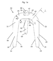
- Fig. 1 a is a side view of a first embodiment of a closure clip according to the present invention.
- closure clip 10 is substantially U-shaped.
- Closure clip 10 comprises two arms 20, 30 which are coupled by a bottom portion 40.
- Arms 20, 30 have first ends 22, 32, which are connected to bottom portion 40 by curved sections 42, 44. Arms 20, 30 further comprise free ends 24, 34. Arms 20, 30 are aligned parallel to each other, thereby defining a plane. Bottom section 40 is arranged in said plane and aligned substantially rectangular to arms 20, 30. Arms 20, 30 have inner surfaces 26, 36 facing inside closure clip 10, and outer surfaces 28, 38 facing away from closure clip 10. Bottom section 40 has an inner surface 46 facing inside closure clip 10, and an outer surface 48 facing away from closure clip 10. Curved sections 42, 44 have inner radii Ri and outer radii Ra.
- closure clip 10 comprises an arbor 50, which is attached to the inner surface 46 of bottom portion 40.
- Arbor 50 has a first end 52 which is coupled to inner surface 46 of bottom portion 40, and a second end 54 facing away from bottom portion 40.
- Arbor 50 extends in the plane defined by arms 20, 30 and substantially parallel to arms 20, 30.
- arbor 50 has a circular cross section tapering towards second end 54.
- Second end 54 terminates in a spike.
- a cam 60 extends approximately from the center of outer surface 48 of bottom portion 40, opposite to arbor 50.
- Cam 60 has a semi-circular cross section.
- Closure clip 10 further has a protrusion 70 forming a bar. Said bar 70 is arranged at a side surface of bottom portion 40. Closure clips 10 are connected via bar 70 to each other building a line of clip which may be stored on a clip supply, like a clip reel.
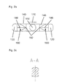
- Fig. 2a is a side view to a second embodiment of a closure clip according to the present invention.
- elements, having the same function and the same configuration, are designated with identical reference signs increased by 100.
- Closure clip 110 is substantially U-shaped.
- Closure clip 110 comprises two arms 120, 130 having first ends 122, 132 and second ends 124, 134. First end 122, 132 of arms 120, 130 are coupled to a bottom portion 140.
- arms 120, 130 of closure clip 110 are aligned parallel to each other, thereby defining a plane.
- Bottom section 140 is arranged in said plane and aligned substantially rectangular to arms 120, 130.
- Arms 120, 130 have inner surfaces 126, 136 facing inside closure clip 110, and outer surfaces 28, 38 facing away from closure clip 110.
- Bottom section 140 has an inner surface 46 facing inside closure clip 10, and an outer surface 48 facing away from closure clip 110.
- Curved sections 142, 144 have inner radii Ri and outer radii Ra.
- closure clip 110 comprises an arbor 150, which is attached to the inner surface 146 of bottom portion 140.
- Arbor 150 has a first end 152 which is coupled to inner surface 146 of bottom portion 140, and a second end 154 facing away from bottom portion 140.
- Arbor 150 extends in the plane defined by arms 120, 130 and substantially parallel to arms 120, 130.
- arbor 150 has a circular cross section tapering towards second end 154. Second end 154 of arbor 150 terminates in a spike.
- a cam 160 extends approximately from the center of outer surface 148 of bottom portion 140, opposite to arbor 150.
- Cam 160 has a semi-circular cross section.
- Closure clip 110 further has a protrusion 170 forming a bar. Said bar 170 is arranged at a side surface of bottom portion 140. Closure clips 110 are connected via bar 170 to each other building a line of clip which may be stored on a clip supply, like a clip reel.
- closure clip 110 further comprises guide means 180 in form of fins, which are attached to the inner surfaces 126, 136 of arms 120, 130, facing to the inside of clip 110.
- Fins 180 are identically, tilted triangular pyramids having a top 182.
- Each of said triangular pyramids has a base formed by an isosceles triangle with which they are attached to the inner surfaces 126, 136 of arms 120, 130.
- the tip of said triangle formed by the identical legs is aligned to the free ends 124, 134 of arms 120, 130.
- the basis of the triangle faces bottom portion 40.
- Tops 182 of said tilted triangular pyramids or fins 180 extend in a direction towards the first end 152 of arbor 150.
- Each fin 180 further comprises two identical side surfaces 184 touching to each other along a common side forming edges 186. Said edges 186 extend from the tip of the triangular bases to top 182 of fins 180, thereby forming a guide channel tapering from free ends 124, 134 of arms 120, 130 towards tops 182 of fins 180. According to the second embodiment of the closure clip, tops 182 of fins 180 thereby passing spike 154 of arbor 150.
- Fig. 3 is a schematic and perspective view to a die for closing a closure clip according to the present invention.
- Die 200 has a substantially cuboid die body 210 including a first, horizontal top surface 220, a second, vertical front surface 230 and a third, vertical side surface 240.
- An approximately semicircular recess 222 extends from the center of horizontal top surface 220 into die body 200.
- Two guide channels 224 are incorporated into the surface of semicircular recess 222.
- Guide channels 224 are arranged parallel to each other.
- An acute angle is compassed between guide channels 224 and side surface 240.
- a land 226 separates guide channels 224.
- land 226 In its central region, land 226 comprises a recess 227 in the form of a cutout which passes the complete height of land 226.
- a bore 228 extends from cutout 227 into die body 200. Bore 228 is arranged vertically to top surface 220 and parallel to side surfaces 230, 240 of the die body 200.
- Die body 200 further comprises a mounting hole 250 for mounting die body 200 to a tool holder or a closing lever of a clipping machine.
- Mounting hole 250 is arranged horizontally and breaks through die body 200 from the centre of side surface 240 to the centre of the opposite side surface (not shown in Fig. 3 ). As it can be seen in Fig. 3 , all edges of die body 200 are chamfered to prevent an operator from being injured or a closure clip from being damaged.
- said packing casing closed at one end is manually or automatically filled with a predetermined portion or number of goods, e.g. in a clipping machine. Thereafter, the open end of the filled casing portion is gathered by the displacer elements of the clipping machine, thereby forming a plait-like portion.
- the clipping machine further comprises a punch and die assembly for attaching and closing a closure clip to the plait-like portion.
- a closure clip 10, 110 positioned in the moving path of the punch is conveyed by the punch via guide notches towards die 200, with the free ends 24, 34, 124, 134 of the arms 20, 30, 120, 130 facing die 200.
- the guide notches for closure clip 10, 110 to be guided toward die 200 by the punch are aligned to guide channels 224 of die 200.
- the plait-like portion of the packing casing is positioned in the conveying path so that closure clip 10, 110 surrounds the plait-like portion. While further moving closure clip 10, 110 towards die 200, free ends 24, 34, 124, 134 immerse in guide channels 224 and are guided along each other while being bent around the plait-like portion of the packing casing.
- guide channels 224 of die 200 are separated by land 226, arms 20, 30, 120, 130 of closure clip 10, 110 are spaced from each other when being bent around the plait-like portion.
- the gap between arms 20, 30, 120, 130 corresponds to the width of land 226 of die 200.
- closure clip 10, 110 comprises an arbor 50, 150 extending from the inner surface 46, 146 of bottom portion 40, 140 towards the free ends 24, 34, 124, 134 of arms 20, 30, 120, 130 and parallel thereto. While attaching closure clip to the plait-like portion, arbor 50, 150 penetrates the plait-like portion and, in the case that the length of arbor 50, 150 exceeds the diameter of the plait-like portion, arbor 50, 150 extends through the plait-like portion.
- arbor 50, 150 may immerse in bore 228 extending from recess 227 in land 226 toward the centre of die body 210.
- the length of arbor 50, 150 amounts at least to the sum of inner radius Ri of curved section 42, 44, 142, 144 and the diameter of arm 20, 30, 120, 130 for surely extend through the plait-like portion.
- the diameter of bore 228 corresponds at least approximately to the diameter of arbor 50, 150 in the region of its first end 52, 152.
- arms 20, 30, 120, 130 are bent around the plait-like portion of the packing casing with a gap there between.
- Arbor 50, 150 extends through the plait-like portion and into the gap between arms 20, 30, 120, 130.
- closure clip 10, 110 In the case of a force acting on the closed packing casing and/or on closing clip 10, 110, urging closing clip 10, 110 to slip off the plait-like portion, free, second end 54, 154 of arbor 50, 150, which extends through the plait-like portion, is supported by one of arms 20, 30, 120, 130 bent around plait-like portion. Thereby closure clip 10, 110 is prevented from slipping off the plait-like portion. Since arbor 50, 150 at least partially absorbs forces acting on closure clip 10, 110, closure clip 10, 110 may be closed with a lower closing force and/or may be made of plastic material having a lesser strength than metal.
- closure clip 110 additionally to the features of closure clip 10 of the first embodiment, comprises guide means in the form of fins 180. Fins 180 are identical, tilted triangular pyramids having a top 182.
- fins 180 are attached to the inner surfaces 126, 136 of arms 120, 130 by their triangular base planes.
- the tip of said triangle formed by the identical legs is aligned to the free ends 124, 134 of arms 120, 130.
- the basis of the triangle faces bottom portion 40.
- Tops 182 of said tilted triangular pyramids or fins 180 extend in a direction towards the first end 152 of arbor 150.
- Edges 186 formed by the respective two identical side surfaces 184 extend from the tip of the triangular bases to top 182 of fins 180, thereby forming a guide channel tapering from free ends 124, 134 of arms 120, 130 towards tops 182 of fins 180.
- closure clip 110 for closing a bag-shaped or tubular packing casing
- the plait-like portion formed by the displacer elements is guided by fins 180 towards arbor 50, 150.
- the plait-like portion of the bag-shaped or tubular packing casing is guided toward the spike formed by second end 154 of arbor 150; thereby the plait-like portion will be compressed or at least halt in its present compressed state by fins 180.
- arbor 150 penetrates the plate-like portion of bag-shaped or tubular packing casing, fins 180 supporting the plait-like portion and preventing the plait-like portion from expanding or leaving its compressed state.
- closure clip 10, 110 comprises a cam 60, 160.
- a punch for being used in conjunction with clip 10, 110 naturally comprises a respective notch for being engaged by cam 60, 160, preventing closure clip 10, 110 from turning while being moved towards die 200 by the punch.
- closure clip has a substantially rectangular cross section.
- Clip 10, 110 may also have any other suitable cross section, like a circular or triangular cross section.
- arbor 50, 150 may have other than a circular cross section, e.g. a rectangular or triangular cross section.
Landscapes
- Engineering & Computer Science (AREA)
- Mechanical Engineering (AREA)
- Package Closures (AREA)
- Bag Frames (AREA)
Priority Applications (4)
| Application Number | Priority Date | Filing Date | Title |
|---|---|---|---|
| EP20100003830 EP2374724B1 (fr) | 2010-04-09 | 2010-04-09 | Clip de fermeture et moule pour fermer ce clip |
| ES10003830.6T ES2523867T3 (es) | 2010-04-09 | 2010-04-09 | Presilla de cierre y matriz para cerrar dicha presilla |
| US13/083,370 US9003610B2 (en) | 2010-04-09 | 2011-04-08 | Closure clip and die for closing said clip |
| BRPI1101505-5A BRPI1101505A2 (pt) | 2010-04-09 | 2011-04-11 | grampo de fechamento de matriz para fechamento do referido grampo |
Applications Claiming Priority (1)
| Application Number | Priority Date | Filing Date | Title |
|---|---|---|---|
| EP20100003830 EP2374724B1 (fr) | 2010-04-09 | 2010-04-09 | Clip de fermeture et moule pour fermer ce clip |
Publications (2)
| Publication Number | Publication Date |
|---|---|
| EP2374724A1 true EP2374724A1 (fr) | 2011-10-12 |
| EP2374724B1 EP2374724B1 (fr) | 2014-09-17 |
Family
ID=42288451
Family Applications (1)
| Application Number | Title | Priority Date | Filing Date |
|---|---|---|---|
| EP20100003830 Active EP2374724B1 (fr) | 2010-04-09 | 2010-04-09 | Clip de fermeture et moule pour fermer ce clip |
Country Status (4)
| Country | Link |
|---|---|
| US (1) | US9003610B2 (fr) |
| EP (1) | EP2374724B1 (fr) |
| BR (1) | BRPI1101505A2 (fr) |
| ES (1) | ES2523867T3 (fr) |
Cited By (2)
| Publication number | Priority date | Publication date | Assignee | Title |
|---|---|---|---|---|
| RU2772499C1 (ru) * | 2020-10-01 | 2022-05-23 | Поли-Клип Зюстем Гмбх Унд Ко. Кг | Свободно устанавливаемый фиксатор клипсовой ленты для фиксации свободного конца клипсовой ленты на катушке для клипс |
| US12312203B2 (en) | 2020-10-01 | 2025-05-27 | Poly-Clip System Gmbh & Co. Kg | Freely positionable clip line fixture for securing a free end of a clip line to a clip reel |
Families Citing this family (4)
| Publication number | Priority date | Publication date | Assignee | Title |
|---|---|---|---|---|
| US10362867B2 (en) * | 2014-10-15 | 2019-07-30 | Judith A. Williams | Pillow rack |
| USD880296S1 (en) | 2018-09-25 | 2020-04-07 | Klr Systems Inc. | Bag closure clip |
| USD871212S1 (en) | 2018-09-25 | 2019-12-31 | Klr Systems Inc. | Bag closure clip |
| EP4265534B1 (fr) * | 2022-03-04 | 2024-11-20 | Containment Service Providers Company Limited | Dispositif de sertissage de doublure |
Citations (5)
| Publication number | Priority date | Publication date | Assignee | Title |
|---|---|---|---|---|
| DE19527875A1 (de) * | 1995-07-29 | 1997-01-30 | Poly Clip System Gmbh & Co Kg | Verschlußklammer für Beutel und Schläuche |
| EP0809592A1 (fr) | 1995-02-17 | 1997-12-03 | Polyclip System Gmbh & Co.Kg | Chaine de clips de fermeture et dispositif et procede de fermeture desdits clips |
| DE19700692A1 (de) * | 1997-01-11 | 1998-07-23 | Poly Clip System Gmbh & Co Kg | Verschlußklammer für Beutel und Schläuche sowie Matrize für ihre Verarbeitung |
| US20070289252A1 (en) * | 2005-02-04 | 2007-12-20 | Poly-Clip System Corp. | Clip and clipper |
| EP1970321A1 (fr) * | 2007-03-16 | 2008-09-17 | Poly-clip System GmbH & Co. KG | Pince de fermeture dotée d'un fond circulaire |
Family Cites Families (20)
| Publication number | Priority date | Publication date | Assignee | Title |
|---|---|---|---|---|
| US403567A (en) | 1889-05-21 | Pencil-holder | ||
| US1230246A (en) | 1916-08-05 | 1917-06-19 | Badger Basket & Veneer Co | Rope-handle-securing staple. |
| US1654371A (en) * | 1926-03-22 | 1927-12-27 | Earl G Oppenheim | Staple |
| US2782673A (en) | 1952-03-10 | 1957-02-26 | E B Packard Co Inc | Multi-pronged sheet metal corner fastener |
| US2748645A (en) * | 1955-01-04 | 1956-06-05 | Robert L Brown | Bendable sheet metal wedging fastener |
| US3584347A (en) * | 1970-05-27 | 1971-06-15 | Rheem Mfg Co | Clipping device |
| DE2605671C3 (de) * | 1976-02-13 | 1980-05-22 | Herbert Dipl.-Ing. 6240 Koenigstein Niedecker | Verschlußklammer |
| US4454875A (en) | 1982-04-15 | 1984-06-19 | Techmedica, Inc. | Osteal medical staple |
| WO1986002618A1 (fr) | 1984-10-31 | 1986-05-09 | Brown Christine C | Fermetures reutilisables et leur fabrication, et systemes d'emballage utilisant ces fermetures |
| US4960420A (en) | 1988-08-23 | 1990-10-02 | Marlowe Goble E | Channel ligament clamp and system |
| US5314065A (en) | 1993-05-03 | 1994-05-24 | L&P Property Management Company | Sheet metal clip |
| US5715987A (en) * | 1994-04-05 | 1998-02-10 | Tracor Incorporated | Constant width, adjustable grip, staple apparatus and method |
| US5809723A (en) | 1997-07-17 | 1998-09-22 | H.K. Composites, Inc. | Multi-prong connectors used in making highly insulated composite wall structures |
| US6173836B1 (en) | 1998-07-15 | 2001-01-16 | Avery Dennison Corporation | Fastener clip |
| JP2003026198A (ja) | 2001-07-11 | 2003-01-29 | Max Co Ltd | クリップ |
| US6957756B2 (en) * | 2002-04-10 | 2005-10-25 | Illinois Tool Works Inc. | Tool with nosepiece for bending fastener upon installation and fastener therefor |
| CN201037490Y (zh) | 2007-03-20 | 2008-03-19 | 曹国强 | 多向附着力的锚固钉 |
| US8602286B2 (en) * | 2009-01-26 | 2013-12-10 | Ethicon Endo-Surgery, Inc. | Apparatus for feeding staples in a low profile surgical stapler |
| US8523506B2 (en) | 2009-08-14 | 2013-09-03 | Brian Macdonald | Cable staple |
| US20110078970A1 (en) | 2009-10-01 | 2011-04-07 | Certainteed Corporation | Ceiling tile and edge suspension system |
-
2010
- 2010-04-09 EP EP20100003830 patent/EP2374724B1/fr active Active
- 2010-04-09 ES ES10003830.6T patent/ES2523867T3/es active Active
-
2011
- 2011-04-08 US US13/083,370 patent/US9003610B2/en active Active
- 2011-04-11 BR BRPI1101505-5A patent/BRPI1101505A2/pt not_active IP Right Cessation
Patent Citations (5)
| Publication number | Priority date | Publication date | Assignee | Title |
|---|---|---|---|---|
| EP0809592A1 (fr) | 1995-02-17 | 1997-12-03 | Polyclip System Gmbh & Co.Kg | Chaine de clips de fermeture et dispositif et procede de fermeture desdits clips |
| DE19527875A1 (de) * | 1995-07-29 | 1997-01-30 | Poly Clip System Gmbh & Co Kg | Verschlußklammer für Beutel und Schläuche |
| DE19700692A1 (de) * | 1997-01-11 | 1998-07-23 | Poly Clip System Gmbh & Co Kg | Verschlußklammer für Beutel und Schläuche sowie Matrize für ihre Verarbeitung |
| US20070289252A1 (en) * | 2005-02-04 | 2007-12-20 | Poly-Clip System Corp. | Clip and clipper |
| EP1970321A1 (fr) * | 2007-03-16 | 2008-09-17 | Poly-clip System GmbH & Co. KG | Pince de fermeture dotée d'un fond circulaire |
Cited By (2)
| Publication number | Priority date | Publication date | Assignee | Title |
|---|---|---|---|---|
| RU2772499C1 (ru) * | 2020-10-01 | 2022-05-23 | Поли-Клип Зюстем Гмбх Унд Ко. Кг | Свободно устанавливаемый фиксатор клипсовой ленты для фиксации свободного конца клипсовой ленты на катушке для клипс |
| US12312203B2 (en) | 2020-10-01 | 2025-05-27 | Poly-Clip System Gmbh & Co. Kg | Freely positionable clip line fixture for securing a free end of a clip line to a clip reel |
Also Published As
| Publication number | Publication date |
|---|---|
| EP2374724B1 (fr) | 2014-09-17 |
| BRPI1101505A2 (pt) | 2012-10-30 |
| ES2523867T3 (es) | 2014-12-02 |
| US20110247300A1 (en) | 2011-10-13 |
| US9003610B2 (en) | 2015-04-14 |
Similar Documents
| Publication | Publication Date | Title |
|---|---|---|
| US9003610B2 (en) | Closure clip and die for closing said clip | |
| US7565780B2 (en) | Clip and clipper | |
| EP3094564B1 (fr) | Dispositif de ficelage amélioré | |
| HU199067B (en) | Method and apparatus for fixing suspension elements on filled goods e.g. sausages | |
| EP2574566A1 (fr) | Pince de fermeture possédant plusieurs crampons | |
| EP2907392B1 (fr) | Machine de fermeture par clip comportant une manipulation améliorée des éléments de suspension | |
| JP3233379U (ja) | 物品結束用器具 | |
| EP2986524B1 (fr) | Recipient pour produits de fruit et legume et procede de fabrication du recipient et d'emballage de tels produits | |
| EP2572585A1 (fr) | Dispositif de transport avec roues en étoile | |
| EP2684459A1 (fr) | Ensemble outil de fermeture par clip | |
| RU2546863C1 (ru) | Закрывающая клипса | |
| EP2752118A1 (fr) | Ensemble de transport avec dispositif de séparation | |
| US20070137142A1 (en) | Clip and clipper | |
| US20040211156A1 (en) | Method and device for manufacturing tubular packs filled with a material as well as tubular pack filled with a material | |
| JP3197527U (ja) | 面状結束バンド連結体及び面状結束バンド結束装置 | |
| US20060174590A1 (en) | Net clip and clipper | |
| FR2886923A1 (fr) | Procede de livraison a un magasin puis d'accrochage simultane sur une broche equipant un lineaire de celui-ci d'une serie d'articles conditionnes dans des emballages | |
| FR3167932A1 (fr) | Machine pour lier par ficelage un premier produit à un deuxième produit | |
| EP1981764A2 (fr) | Attache et dispositif d'attache | |
| JP2005231690A (ja) | 包装用補助具 |
Legal Events
| Date | Code | Title | Description |
|---|---|---|---|
| PUAI | Public reference made under article 153(3) epc to a published international application that has entered the european phase |
Free format text: ORIGINAL CODE: 0009012 |
|
| AK | Designated contracting states |
Kind code of ref document: A1 Designated state(s): AT BE BG CH CY CZ DE DK EE ES FI FR GB GR HR HU IE IS IT LI LT LU LV MC MK MT NL NO PL PT RO SE SI SK SM TR |
|
| AX | Request for extension of the european patent |
Extension state: AL BA ME RS |
|
| 17P | Request for examination filed |
Effective date: 20111028 |
|
| 17Q | First examination report despatched |
Effective date: 20111208 |
|
| RAP1 | Party data changed (applicant data changed or rights of an application transferred) |
Owner name: POLY-CLIP SYSTEM GMBH & CO. KG |
|
| GRAP | Despatch of communication of intention to grant a patent |
Free format text: ORIGINAL CODE: EPIDOSNIGR1 |
|
| INTG | Intention to grant announced |
Effective date: 20140507 |
|
| GRAS | Grant fee paid |
Free format text: ORIGINAL CODE: EPIDOSNIGR3 |
|
| GRAA | (expected) grant |
Free format text: ORIGINAL CODE: 0009210 |
|
| AK | Designated contracting states |
Kind code of ref document: B1 Designated state(s): AT BE BG CH CY CZ DE DK EE ES FI FR GB GR HR HU IE IS IT LI LT LU LV MC MK MT NL NO PL PT RO SE SI SK SM TR |
|
| REG | Reference to a national code |
Ref country code: GB Ref legal event code: FG4D |
|
| REG | Reference to a national code |
Ref country code: CH Ref legal event code: EP |
|
| REG | Reference to a national code |
Ref country code: IE Ref legal event code: FG4D |
|
| REG | Reference to a national code |
Ref country code: AT Ref legal event code: REF Ref document number: 687576 Country of ref document: AT Kind code of ref document: T Effective date: 20141015 |
|
| REG | Reference to a national code |
Ref country code: DE Ref legal event code: R096 Ref document number: 602010018963 Country of ref document: DE Effective date: 20141030 |
|
| REG | Reference to a national code |
Ref country code: CH Ref legal event code: NV Representative=s name: RENTSCH PARTNER AG, CH |
|
| REG | Reference to a national code |
Ref country code: ES Ref legal event code: FG2A Ref document number: 2523867 Country of ref document: ES Kind code of ref document: T3 Effective date: 20141202 |
|
| PG25 | Lapsed in a contracting state [announced via postgrant information from national office to epo] |
Ref country code: SE Free format text: LAPSE BECAUSE OF FAILURE TO SUBMIT A TRANSLATION OF THE DESCRIPTION OR TO PAY THE FEE WITHIN THE PRESCRIBED TIME-LIMIT Effective date: 20140917 Ref country code: NO Free format text: LAPSE BECAUSE OF FAILURE TO SUBMIT A TRANSLATION OF THE DESCRIPTION OR TO PAY THE FEE WITHIN THE PRESCRIBED TIME-LIMIT Effective date: 20141217 Ref country code: LT Free format text: LAPSE BECAUSE OF FAILURE TO SUBMIT A TRANSLATION OF THE DESCRIPTION OR TO PAY THE FEE WITHIN THE PRESCRIBED TIME-LIMIT Effective date: 20140917 Ref country code: GR Free format text: LAPSE BECAUSE OF FAILURE TO SUBMIT A TRANSLATION OF THE DESCRIPTION OR TO PAY THE FEE WITHIN THE PRESCRIBED TIME-LIMIT Effective date: 20141218 Ref country code: FI Free format text: LAPSE BECAUSE OF FAILURE TO SUBMIT A TRANSLATION OF THE DESCRIPTION OR TO PAY THE FEE WITHIN THE PRESCRIBED TIME-LIMIT Effective date: 20140917 |
|
| REG | Reference to a national code |
Ref country code: NL Ref legal event code: VDEP Effective date: 20140917 |
|
| REG | Reference to a national code |
Ref country code: LT Ref legal event code: MG4D |
|
| PG25 | Lapsed in a contracting state [announced via postgrant information from national office to epo] |
Ref country code: HR Free format text: LAPSE BECAUSE OF FAILURE TO SUBMIT A TRANSLATION OF THE DESCRIPTION OR TO PAY THE FEE WITHIN THE PRESCRIBED TIME-LIMIT Effective date: 20140917 Ref country code: CY Free format text: LAPSE BECAUSE OF FAILURE TO SUBMIT A TRANSLATION OF THE DESCRIPTION OR TO PAY THE FEE WITHIN THE PRESCRIBED TIME-LIMIT Effective date: 20140917 Ref country code: LV Free format text: LAPSE BECAUSE OF FAILURE TO SUBMIT A TRANSLATION OF THE DESCRIPTION OR TO PAY THE FEE WITHIN THE PRESCRIBED TIME-LIMIT Effective date: 20140917 |
|
| REG | Reference to a national code |
Ref country code: AT Ref legal event code: MK05 Ref document number: 687576 Country of ref document: AT Kind code of ref document: T Effective date: 20140917 |
|
| PG25 | Lapsed in a contracting state [announced via postgrant information from national office to epo] |
Ref country code: NL Free format text: LAPSE BECAUSE OF FAILURE TO SUBMIT A TRANSLATION OF THE DESCRIPTION OR TO PAY THE FEE WITHIN THE PRESCRIBED TIME-LIMIT Effective date: 20140917 |
|
| PG25 | Lapsed in a contracting state [announced via postgrant information from national office to epo] |
Ref country code: SK Free format text: LAPSE BECAUSE OF FAILURE TO SUBMIT A TRANSLATION OF THE DESCRIPTION OR TO PAY THE FEE WITHIN THE PRESCRIBED TIME-LIMIT Effective date: 20140917 Ref country code: RO Free format text: LAPSE BECAUSE OF FAILURE TO SUBMIT A TRANSLATION OF THE DESCRIPTION OR TO PAY THE FEE WITHIN THE PRESCRIBED TIME-LIMIT Effective date: 20140917 Ref country code: PT Free format text: LAPSE BECAUSE OF FAILURE TO SUBMIT A TRANSLATION OF THE DESCRIPTION OR TO PAY THE FEE WITHIN THE PRESCRIBED TIME-LIMIT Effective date: 20150119 Ref country code: EE Free format text: LAPSE BECAUSE OF FAILURE TO SUBMIT A TRANSLATION OF THE DESCRIPTION OR TO PAY THE FEE WITHIN THE PRESCRIBED TIME-LIMIT Effective date: 20140917 Ref country code: CZ Free format text: LAPSE BECAUSE OF FAILURE TO SUBMIT A TRANSLATION OF THE DESCRIPTION OR TO PAY THE FEE WITHIN THE PRESCRIBED TIME-LIMIT Effective date: 20140917 Ref country code: IS Free format text: LAPSE BECAUSE OF FAILURE TO SUBMIT A TRANSLATION OF THE DESCRIPTION OR TO PAY THE FEE WITHIN THE PRESCRIBED TIME-LIMIT Effective date: 20150117 |
|
| PG25 | Lapsed in a contracting state [announced via postgrant information from national office to epo] |
Ref country code: PL Free format text: LAPSE BECAUSE OF FAILURE TO SUBMIT A TRANSLATION OF THE DESCRIPTION OR TO PAY THE FEE WITHIN THE PRESCRIBED TIME-LIMIT Effective date: 20140917 Ref country code: AT Free format text: LAPSE BECAUSE OF FAILURE TO SUBMIT A TRANSLATION OF THE DESCRIPTION OR TO PAY THE FEE WITHIN THE PRESCRIBED TIME-LIMIT Effective date: 20140917 |
|
| REG | Reference to a national code |
Ref country code: DE Ref legal event code: R097 Ref document number: 602010018963 Country of ref document: DE |
|
| PLBE | No opposition filed within time limit |
Free format text: ORIGINAL CODE: 0009261 |
|
| STAA | Information on the status of an ep patent application or granted ep patent |
Free format text: STATUS: NO OPPOSITION FILED WITHIN TIME LIMIT |
|
| PG25 | Lapsed in a contracting state [announced via postgrant information from national office to epo] |
Ref country code: DK Free format text: LAPSE BECAUSE OF FAILURE TO SUBMIT A TRANSLATION OF THE DESCRIPTION OR TO PAY THE FEE WITHIN THE PRESCRIBED TIME-LIMIT Effective date: 20140917 |
|
| 26N | No opposition filed |
Effective date: 20150618 |
|
| PGFP | Annual fee paid to national office [announced via postgrant information from national office to epo] |
Ref country code: IT Payment date: 20150428 Year of fee payment: 6 |
|
| PG25 | Lapsed in a contracting state [announced via postgrant information from national office to epo] |
Ref country code: MC Free format text: LAPSE BECAUSE OF FAILURE TO SUBMIT A TRANSLATION OF THE DESCRIPTION OR TO PAY THE FEE WITHIN THE PRESCRIBED TIME-LIMIT Effective date: 20140917 Ref country code: LU Free format text: LAPSE BECAUSE OF FAILURE TO SUBMIT A TRANSLATION OF THE DESCRIPTION OR TO PAY THE FEE WITHIN THE PRESCRIBED TIME-LIMIT Effective date: 20150409 Ref country code: SI Free format text: LAPSE BECAUSE OF FAILURE TO SUBMIT A TRANSLATION OF THE DESCRIPTION OR TO PAY THE FEE WITHIN THE PRESCRIBED TIME-LIMIT Effective date: 20140917 |
|
| GBPC | Gb: european patent ceased through non-payment of renewal fee |
Effective date: 20150409 |
|
| REG | Reference to a national code |
Ref country code: IE Ref legal event code: MM4A |
|
| PG25 | Lapsed in a contracting state [announced via postgrant information from national office to epo] |
Ref country code: GB Free format text: LAPSE BECAUSE OF NON-PAYMENT OF DUE FEES Effective date: 20150409 |
|
| REG | Reference to a national code |
Ref country code: FR Ref legal event code: ST Effective date: 20151231 |
|
| PG25 | Lapsed in a contracting state [announced via postgrant information from national office to epo] |
Ref country code: FR Free format text: LAPSE BECAUSE OF NON-PAYMENT OF DUE FEES Effective date: 20150430 |
|
| PG25 | Lapsed in a contracting state [announced via postgrant information from national office to epo] |
Ref country code: IE Free format text: LAPSE BECAUSE OF NON-PAYMENT OF DUE FEES Effective date: 20150409 |
|
| PGFP | Annual fee paid to national office [announced via postgrant information from national office to epo] |
Ref country code: CH Payment date: 20160422 Year of fee payment: 7 |
|
| PG25 | Lapsed in a contracting state [announced via postgrant information from national office to epo] |
Ref country code: MT Free format text: LAPSE BECAUSE OF FAILURE TO SUBMIT A TRANSLATION OF THE DESCRIPTION OR TO PAY THE FEE WITHIN THE PRESCRIBED TIME-LIMIT Effective date: 20140917 |
|
| PG25 | Lapsed in a contracting state [announced via postgrant information from national office to epo] |
Ref country code: IT Free format text: LAPSE BECAUSE OF NON-PAYMENT OF DUE FEES Effective date: 20160409 |
|
| PG25 | Lapsed in a contracting state [announced via postgrant information from national office to epo] |
Ref country code: SM Free format text: LAPSE BECAUSE OF FAILURE TO SUBMIT A TRANSLATION OF THE DESCRIPTION OR TO PAY THE FEE WITHIN THE PRESCRIBED TIME-LIMIT Effective date: 20140917 Ref country code: BG Free format text: LAPSE BECAUSE OF FAILURE TO SUBMIT A TRANSLATION OF THE DESCRIPTION OR TO PAY THE FEE WITHIN THE PRESCRIBED TIME-LIMIT Effective date: 20140917 Ref country code: HU Free format text: LAPSE BECAUSE OF FAILURE TO SUBMIT A TRANSLATION OF THE DESCRIPTION OR TO PAY THE FEE WITHIN THE PRESCRIBED TIME-LIMIT; INVALID AB INITIO Effective date: 20100409 |
|
| PG25 | Lapsed in a contracting state [announced via postgrant information from national office to epo] |
Ref country code: TR Free format text: LAPSE BECAUSE OF FAILURE TO SUBMIT A TRANSLATION OF THE DESCRIPTION OR TO PAY THE FEE WITHIN THE PRESCRIBED TIME-LIMIT Effective date: 20140917 |
|
| PG25 | Lapsed in a contracting state [announced via postgrant information from national office to epo] |
Ref country code: BE Free format text: LAPSE BECAUSE OF FAILURE TO SUBMIT A TRANSLATION OF THE DESCRIPTION OR TO PAY THE FEE WITHIN THE PRESCRIBED TIME-LIMIT Effective date: 20140917 |
|
| REG | Reference to a national code |
Ref country code: CH Ref legal event code: PCAR Free format text: NEW ADDRESS: BELLERIVESTRASSE 203 POSTFACH, 8034 ZUERICH (CH) |
|
| REG | Reference to a national code |
Ref country code: CH Ref legal event code: PL |
|
| PG25 | Lapsed in a contracting state [announced via postgrant information from national office to epo] |
Ref country code: CH Free format text: LAPSE BECAUSE OF NON-PAYMENT OF DUE FEES Effective date: 20170430 Ref country code: LI Free format text: LAPSE BECAUSE OF NON-PAYMENT OF DUE FEES Effective date: 20170430 |
|
| PG25 | Lapsed in a contracting state [announced via postgrant information from national office to epo] |
Ref country code: MK Free format text: LAPSE BECAUSE OF FAILURE TO SUBMIT A TRANSLATION OF THE DESCRIPTION OR TO PAY THE FEE WITHIN THE PRESCRIBED TIME-LIMIT Effective date: 20140917 |
|
| P01 | Opt-out of the competence of the unified patent court (upc) registered |
Effective date: 20230522 |
|
| PGFP | Annual fee paid to national office [announced via postgrant information from national office to epo] |
Ref country code: DE Payment date: 20250507 Year of fee payment: 16 |
|
| PGFP | Annual fee paid to national office [announced via postgrant information from national office to epo] |
Ref country code: ES Payment date: 20250519 Year of fee payment: 16 |
|
| REG | Reference to a national code |
Ref country code: DE Ref legal event code: R081 Ref document number: 602010018963 Country of ref document: DE Owner name: POLY-CLIP SYSTEM CONSUMABLES GMBH, DE Free format text: FORMER OWNER: POLY-CLIP SYSTEM GMBH & CO. KG, 60489 FRANKFURT, DE |