EP2374740A2 - Roller of a belt conveyor - Google Patents
Roller of a belt conveyor Download PDFInfo
- Publication number
- EP2374740A2 EP2374740A2 EP20110460007 EP11460007A EP2374740A2 EP 2374740 A2 EP2374740 A2 EP 2374740A2 EP 20110460007 EP20110460007 EP 20110460007 EP 11460007 A EP11460007 A EP 11460007A EP 2374740 A2 EP2374740 A2 EP 2374740A2
- Authority
- EP
- European Patent Office
- Prior art keywords
- hubs
- roller
- sleeves
- conveyor
- belt
- Prior art date
- Legal status (The legal status is an assumption and is not a legal conclusion. Google has not performed a legal analysis and makes no representation as to the accuracy of the status listed.)
- Withdrawn
Links
- 239000002184 metal Substances 0.000 claims abstract description 16
- 238000007789 sealing Methods 0.000 claims abstract description 8
- 238000003466 welding Methods 0.000 claims abstract description 4
- 150000001875 compounds Chemical class 0.000 claims abstract description 3
- 238000005242 forging Methods 0.000 claims abstract description 3
- 238000003754 machining Methods 0.000 claims abstract description 3
- 238000005265 energy consumption Methods 0.000 description 3
- 238000006073 displacement reaction Methods 0.000 description 2
- 239000000463 material Substances 0.000 description 1
- 230000013011 mating Effects 0.000 description 1
- 230000003584 silencer Effects 0.000 description 1
- 125000006850 spacer group Chemical group 0.000 description 1
Images

Classifications
-
- B—PERFORMING OPERATIONS; TRANSPORTING
- B65—CONVEYING; PACKING; STORING; HANDLING THIN OR FILAMENTARY MATERIAL
- B65G—TRANSPORT OR STORAGE DEVICES, e.g. CONVEYORS FOR LOADING OR TIPPING, SHOP CONVEYOR SYSTEMS OR PNEUMATIC TUBE CONVEYORS
- B65G39/00—Rollers, e.g. drive rollers, or arrangements thereof incorporated in roller-ways or other types of mechanical conveyors
- B65G39/02—Adaptations of individual rollers and supports therefor
- B65G39/09—Arrangements of bearing or sealing means
Definitions
- the invention subject-matter is a roller of belt-conveyor used in extractive industry, sugar industry, heat engineering and building industry.
- the roller of a belt-conveyor known from Polish patent No. 164187 has bearings mounted on an axle.
- the bearings have sealings on their both ends and sealing packet on their external surfaces.
- Each bearing together with its sealing are mounted inside two hubs.
- Inside the hubs an elastic ring is located, advisably made of rubber. The ring is separated from the bearing with the help of a spacer sleeve.
- Another roller of belt-conveyor known from the Polish patent No. 170870 has a divided tube housing which consist of two finned sleeves.
- One end of each sleeve is a hub for a bearing and the opposite end of the sleeve is connected with a central ring with the help of nuts mounted on the ends of immovable axle supported in the hubs.
- the finned sleeves and the central ring have conical fit surfaces which close inside chambers of the divided tube housing.
- the roller of belt-conveyor known from Polish patent No. 170831 consists of two finned rolls mounted on conical ends of a movable shaft.
- the bearings of the shaft are mounted in a sleeve situated centrally between the finned rolls.
- the sleeve is connected with a bracket mounted in a slot between the rolls in order to support the roller.
- the roller of belt-conveyor known from Polish utility model No. 62446 consists of an axle and a rotary housing mounted on the axle. The inner surface of the housing is covered with silencer material.
- Purpose of the invention is to construct a roller for the belt-conveyor which will have low resistance to rotary motion, low weight and thus will enable to obtain low energy consumption, lengthen of life and operational reliability. Furthermore, the new roller is characterized by simplicity of structure and easy assembling and disassembling.
- Roller of the belt-conveyor is characterised by that, that it consist of a smooth tube housing closed on both ends with flanged metal hubs.
- the hubs are forged or welded.
- the bases of the half-shafts are sockets situated in cylindrical flanges of the hubs.
- Sleeves having stoppers are mounted on the bearings.
- the sleeves have on their surfaces opposite flat cantings which enable to situate the sleeves in forks of the belt-conveyor frame.
- the tube housing is connected with the hubs by welding.
- Optional solution of belt conveyor is characterized by that, that the metal tube housing is provided with a layer of plastic having low friction factor in order to silence the work of the belt of the conveyor with the ends connected together with metal clamps.
- the advantage of the roller according to the invention is its design simplification, easy assembling and disassembling, low resistance to motion.
- the metal tube housing of the optional roller according to the invention is provided with a plastic layer which enables silent cooperation of the roller and metal joints of the ends of belt. Additional advantage of the invention is low weight of the roller and thereby lower energy consumption and higher lifetime of the roller.
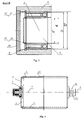
- fig. 1 shows the roller in its longitudinal section and main sideview
- fig.2 shows detail "A” of the roller in longitudinal section
- fig.3 shows detail "B” in longitudinal section
- fig.3 shows the alternative version of the roller in its longitudinal section and its main sideview.
- the roller according to the invention consists of a smooth metal tube housing 1 both ends of which are closed with flanged metal hubs 2.
- the hubs 2 are made of metal by forging or machining.
- Bases for the half-shafts 4 are sockets 6 situated in cylindrical flanges 7 of the hubs 2.
- On split bearings 8 are situated sleeves 9 provided with stoppers 10.
- On the surfaces of the sleeves 9 are made opposite flat cantings 11 which enable mounting the sleeves 9 in forks of non-visualized frame of the conveyor.
- Each of the sockets 6 of the hubs 2 has a pair of compound sealing rings 12 and 13 and plastic throwers 14 shaped like outside-turned flanges.
- the internal rings of the split bearings 8 are mounted on half-shafts 4 on their parts having smaller diameter " d' " and supported on their parts having bigger diameter” d".
- the external rings of the bearings 8 are mounted inside the sleeves 9 on their parts having bigger internal diameter "D' " and supported on their parts having smaller internal diameter " D ".
- the external rings of the split bearings 8 are protected against displacement by stopper rings 15 situated in circumferential grooves 15' which are made inside the sleeves 9 on their parts having bigger internal diameter " D' ".
- the internal rings of the split bearings 8 are protected against displacement with the help of stopper rings 16 situated in circumferential grooves 16' made on the surface of the half-shifts 4 on their parts having smaller diameter "d' ".
- the tube housing 1 is connected to the hubs 2 by welding.
- the smooth metal housing 1 is coated with plastic layer 17 in order to silence the cooperation of the belt conveyor with the ends of belt connected together with metal clamps.
Landscapes
- Engineering & Computer Science (AREA)
- Mechanical Engineering (AREA)
- Structure Of Belt Conveyors (AREA)
Applications Claiming Priority (1)
| Application Number | Priority Date | Filing Date | Title |
|---|---|---|---|
| PL390916A PL217907B1 (pl) | 2010-04-06 | 2010-04-06 | Krążnik przenośnika taśmowego |
Publications (1)
| Publication Number | Publication Date |
|---|---|
| EP2374740A2 true EP2374740A2 (en) | 2011-10-12 |
Family
ID=43013938
Family Applications (1)
| Application Number | Title | Priority Date | Filing Date |
|---|---|---|---|
| EP20110460007 Withdrawn EP2374740A2 (en) | 2010-04-06 | 2011-02-21 | Roller of a belt conveyor |
Country Status (2)
| Country | Link |
|---|---|
| EP (1) | EP2374740A2 (pl) |
| PL (1) | PL217907B1 (pl) |
Cited By (1)
| Publication number | Priority date | Publication date | Assignee | Title |
|---|---|---|---|---|
| CN105059862A (zh) * | 2015-06-30 | 2015-11-18 | 辽宁科技大学 | 一种胶带输送机的半轴滚筒 |
-
2010
- 2010-04-06 PL PL390916A patent/PL217907B1/pl unknown
-
2011
- 2011-02-21 EP EP20110460007 patent/EP2374740A2/en not_active Withdrawn
Cited By (1)
| Publication number | Priority date | Publication date | Assignee | Title |
|---|---|---|---|---|
| CN105059862A (zh) * | 2015-06-30 | 2015-11-18 | 辽宁科技大学 | 一种胶带输送机的半轴滚筒 |
Also Published As
| Publication number | Publication date |
|---|---|
| PL390916A1 (pl) | 2010-10-11 |
| PL217907B1 (pl) | 2014-09-30 |
Similar Documents
| Publication | Publication Date | Title |
|---|---|---|
| KR101129742B1 (ko) | 원통형 롤러가 조립된 롤러 체인 | |
| AU2015210534B2 (en) | Non-concentric protruding shaft fixed bearing reciprocating impact part for implementing reciprocrating impact part non-concentric protruding shaft fixed bearing method | |
| US10105819B2 (en) | Support and coupling assembly for a screw auger having multiple coupled screws | |
| EP2374740A2 (en) | Roller of a belt conveyor | |
| CN104942030B (zh) | 棒材冷床用对齐辊 | |
| US1200445A (en) | Roller-bearing. | |
| CN206655919U (zh) | 一种球形端面圆柱滚子 | |
| CN103192405B (zh) | 采用无圈轴承的外骨骼机器人关节结构 | |
| ES2830776T3 (es) | Embrague de discos múltiples con tope de desplazamiento axial mejorado y aplicación industrial | |
| CN209796549U (zh) | 物料输送传动对称阶梯滚轴链 | |
| CN114165442B (zh) | 一种基于箔片偏心轴承的无油摆动转子压缩机 | |
| CN105387072B (zh) | 一种液压马达用可替代滚动轴承的结构 | |
| CN204689017U (zh) | 改良型托辊 | |
| CN212775230U (zh) | 一种双联型三叉杆滑球式万向联轴器 | |
| CN201836300U (zh) | 侧弯链条 | |
| CN219340717U (zh) | 一种可纠偏皮带的组装式滚筒机构 | |
| JP5933041B2 (ja) | コネクティングロッド用の軸受アセンブリ | |
| CN201377528Y (zh) | 滚柱型式超越离合器 | |
| CN203823312U (zh) | 一种多通路旋转接头 | |
| CN223521719U (zh) | 一种具有自润滑性能的芯棒润滑链 | |
| WO2021110151A1 (zh) | 多排浮动组合式重载超越离合器 | |
| CN222937173U (zh) | 一种长度可调节链条 | |
| CN222836205U (zh) | 一种轮齿可更换式链轮组件 | |
| CN213839298U (zh) | 一种中心传动球磨机用轴瓦 | |
| CN104229415B (zh) | 一种高分子托辊装置 |
Legal Events
| Date | Code | Title | Description |
|---|---|---|---|
| PUAI | Public reference made under article 153(3) epc to a published international application that has entered the european phase |
Free format text: ORIGINAL CODE: 0009012 |
|
| AK | Designated contracting states |
Kind code of ref document: A2 Designated state(s): AL AT BE BG CH CY CZ DE DK EE ES FI FR GB GR HR HU IE IS IT LI LT LU LV MC MK MT NL NO PL PT RO RS SE SI SK SM TR |
|
| AX | Request for extension of the european patent |
Extension state: BA ME |
|
| STAA | Information on the status of an ep patent application or granted ep patent |
Free format text: STATUS: THE APPLICATION IS DEEMED TO BE WITHDRAWN |
|
| 18D | Application deemed to be withdrawn |
Effective date: 20150901 |