EP2374936B2 - Cylindre de fraisage pour une machine à fraiser le sol et machine à fraiser le sol - Google Patents
Cylindre de fraisage pour une machine à fraiser le sol et machine à fraiser le sol Download PDFInfo
- Publication number
- EP2374936B2 EP2374936B2 EP11002790.1A EP11002790A EP2374936B2 EP 2374936 B2 EP2374936 B2 EP 2374936B2 EP 11002790 A EP11002790 A EP 11002790A EP 2374936 B2 EP2374936 B2 EP 2374936B2
- Authority
- EP
- European Patent Office
- Prior art keywords
- milling
- drum
- face
- circumferential surface
- hollow
- Prior art date
- Legal status (The legal status is an assumption and is not a legal conclusion. Google has not performed a legal analysis and makes no representation as to the accuracy of the status listed.)
- Active
Links
Images

Classifications
-
- E—FIXED CONSTRUCTIONS
- E01—CONSTRUCTION OF ROADS, RAILWAYS, OR BRIDGES
- E01C—CONSTRUCTION OF, OR SURFACES FOR, ROADS, SPORTS GROUNDS, OR THE LIKE; MACHINES OR AUXILIARY TOOLS FOR CONSTRUCTION OR REPAIR
- E01C23/00—Auxiliary devices or arrangements for constructing, repairing, reconditioning, or taking-up road or like surfaces
- E01C23/06—Devices or arrangements for working the finished surface; Devices for repairing or reconditioning the surface of damaged paving; Recycling in place or on the road
- E01C23/08—Devices or arrangements for working the finished surface; Devices for repairing or reconditioning the surface of damaged paving; Recycling in place or on the road for roughening or patterning; for removing the surface down to a predetermined depth high spots or material bonded to the surface, e.g. markings; for maintaining earth roads, clay courts or like surfaces by means of surface working tools, e.g. scarifiers, levelling blades
- E01C23/085—Devices or arrangements for working the finished surface; Devices for repairing or reconditioning the surface of damaged paving; Recycling in place or on the road for roughening or patterning; for removing the surface down to a predetermined depth high spots or material bonded to the surface, e.g. markings; for maintaining earth roads, clay courts or like surfaces by means of surface working tools, e.g. scarifiers, levelling blades using power-driven tools, e.g. vibratory tools
- E01C23/088—Rotary tools, e.g. milling drums
-
- B—PERFORMING OPERATIONS; TRANSPORTING
- B28—WORKING CEMENT, CLAY, OR STONE
- B28D—WORKING STONE OR STONE-LIKE MATERIALS
- B28D1/00—Working stone or stone-like materials, e.g. brick, concrete or glass, not provided for elsewhere; Machines, devices, tools therefor
- B28D1/18—Working stone or stone-like materials, e.g. brick, concrete or glass, not provided for elsewhere; Machines, devices, tools therefor by milling, e.g. channelling by means of milling tools
-
- B—PERFORMING OPERATIONS; TRANSPORTING
- B65—CONVEYING; PACKING; STORING; HANDLING THIN OR FILAMENTARY MATERIAL
- B65H—HANDLING THIN OR FILAMENTARY MATERIAL, e.g. SHEETS, WEBS, CABLES
- B65H23/00—Registering, tensioning, smoothing or guiding webs
- B65H23/02—Registering, tensioning, smoothing or guiding webs transversely
- B65H23/022—Registering, tensioning, smoothing or guiding webs transversely by tentering devices
- B65H23/025—Registering, tensioning, smoothing or guiding webs transversely by tentering devices by rollers
- B65H23/0251—Registering, tensioning, smoothing or guiding webs transversely by tentering devices by rollers with a straight axis
-
- B—PERFORMING OPERATIONS; TRANSPORTING
- B65—CONVEYING; PACKING; STORING; HANDLING THIN OR FILAMENTARY MATERIAL
- B65H—HANDLING THIN OR FILAMENTARY MATERIAL, e.g. SHEETS, WEBS, CABLES
- B65H2404/00—Parts for transporting or guiding the handled material
- B65H2404/10—Rollers
- B65H2404/11—Details of cross-section or profile
- B65H2404/115—Details of cross-section or profile other
- B65H2404/1151—Details of cross-section or profile other brush
Definitions
- the invention relates to a milling drum according to the type specified by the preamble of claim 1.
- the invention also relates to a soil milling machine with at least one such milling drum.
- Milling drums of the type in question are used to crush and/or remove soil material, in particular compacted or solid soil material, such as a concrete or tar surface. Such milling drums are often used to remove or partially remove a road surface (or the like). Such milling drums are known, for example, from the DE 698 24 340 T2 , the US 5,775,781 B and the DE 296 13 658 U known.
- a disadvantage of the milling drums of the type in question known from the state of the art is that they are exposed to severe wear during milling operation, especially on the front sides of the drum base body (also known as the drum). Particularly when cornering with a relatively small curve radii (e.g. milling free manhole covers), there is severe abrasion on the front side of the drum on the inside of the curve due to the milling edge formed in the ground material. The abrasion is increased by an undercut in the ground material (so-called undercut) in relation to the milling edge. Attempts are currently being made to protect the front sides of the drum from excessive wear by attaching wear plates. However, this is only partially satisfactory.
- a further disadvantage of the milling drums of the type in question known from the state of the art is that more milled material adheres to the milling drum box.
- the invention is therefore based on the object of further developing a milling drum of the type in question in such a way that the frontal wear on the drum is reduced.
- the milling drum according to the invention comprises a hollow cylindrical and axially extending drum base body, the so-called drum, which is defined with respect to its longitudinal axis by an inner drum radius and an outer drum radius.
- Several milling chisels are attached to the outer peripheral surface or the lateral surface of the hollow cylindrical drum for Crushing and/or removing soil material.
- two front-side milling chisels are arranged in the area of at least one circular end face of the hollow cylindrical bandage, which protrude from the relevant end face or protrude outwards from this end face and which, during milling operation, protect the relevant end face from direct abrasive contact with the soil material to be processed by the contact area or collision area between this end face of the hollow cylindrical bandage and the soil material being virtually cleared or cut free by these two front-side milling chisels.
- the relevant end face of the hollow cylindrical bandage is thereby at least partially protected from abrasion, whereby excessive wear on the relevant end face, as well as on any chisel holders and weld seams on the relevant end face, is avoided or at least significantly reduced.
- An essential aspect of the invention is the direct protection of the relevant front side of the hollow cylindrical drum by two front-side milling cutters, which is why the milling drum according to the invention is particularly suitable for cornering with a relatively small curve radius (e.g. milling free of manhole covers), despite the undercut on the milling edge.
- a relatively small curve radius e.g. milling free of manhole covers
- the two front-side milling cutters are arranged at equal intervals in a circumferential direction.
- the first front-side milling chisel is arranged on at least one front side of the hollow cylindrical bandage in the radial direction (with respect to the longitudinal axis or the axis of rotation of the hollow cylindrical bandage) approximately centrally between the inner radius of the bandage and the outer radius of the bandage or between the inner circumferential surface and the outer circumferential surface of the hollow cylindrical bandage.
- the cutting circle produced by this front-side milling chisel is located approximately centrally on the circular ring-shaped front side of the hollow cylindrical bandage.
- the two front-side milling cutters are arranged directly in the bandage on the front side of the hollow cylindrical bandage.
- the hollow cylindrical bandage is designed accordingly on the front side in question and has pockets, as explained in more detail below in connection with the figures.
- the two front-side milling chisels arranged on the front side of the hollow cylindrical bandage are designed as replaceable milling chisels.
- chisel change holders are arranged on the hollow cylindrical bandage, to which the replaceable front-side milling chisels are attached.
- the axial longitudinal extension of the milling drum is greater than the (maximum) diameter of this milling drum.
- the axial longitudinal extension is several times greater.
- the axial longitudinal extension of the milling drum is smaller than the (maximum) diameter of this milling drum.
- a milling drum can also be referred to as a milling rotor.
- the solution to the problem also extends to a ground milling machine with a driver's platform (large milling machine), comprising at least one milling drum according to the invention.
- a ground milling machine with a driver's platform large milling machine
- This is in particular a road milling machine.
- the solution to the problem also extends to a hand-held ground milling machine (compact milling machine), comprising at least one milling drum according to the invention.
- a hand-held ground milling machine comprising at least one milling drum according to the invention.
- This is in particular a road milling machine.
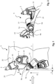
- Fig. 1 shows a milling drum according to the invention, designated overall by 1.
- the milling drum 1 includes a drum base body which is designed as a hollow cylindrical drum 2 and on whose outer circumferential surface or lateral surface 22 several milling chisels 3 and 4 are arranged for crushing and/or removing soil material.
- the milling chisels 3 and 4 are, for example, replaceable milling chisels which are attached to the drum 2 by means of chisel change holders 31 and 41.
- the chisel change holders 31 and 41 are in turn welded to the drum 2, for example.
- the longitudinal axis of the milling drum 1 and the drum 2 is indicated by L.
- the longitudinal axis L coincides with the axis of rotation.
- the direction of rotation (or direction of revolution or milling direction) of the milling drum 1 for milling operation is indicated by D.
- the milling chisels 3 are aligned with their milling chisel longitudinal axes essentially in the direction of rotation D, for example.
- the milling chisels 3 can also be angled with respect to the direction of rotation D.
- the left front side of the drum 2 is designated with 21.
- the angled milling chisels 4, which protrude beyond the front side 21, serve to create a defined milling edge in the soil material to be worked. However, no protection for the front side 21 can be achieved using these milling chisels 4.
- two front milling chisels 5a and 5b are arranged in the front area.
- the front-side milling chisels 5a and 5b protrude beyond the left front side 21 by a defined amount x (e.g. several millimeters) and are intended to at least partially cut or clear the collision area between this front side 21 and the soil material to be processed during milling operation in order to prevent direct contact between the front side 21 and the soil material remaining during milling. essentially to avoid.
- x e.g. several millimeters
- the relevant collision area on the front side 21 is indicated as radial section T (which essentially corresponds to the thickness of the drum 2).
- the front-side milling cutters 5a and 5b can cut free an area that exceeds this radial section T radially inwards and/or radially outwards.
- the front milling cutters 5a and 5b are also designed as exchangeable milling cutters, which are attached to the drum 2 by means of cutter change holders 51.
- the cutter change holders 51 are arranged in pockets 6a and 6b, as described below in connection with the Fig. 4
- the front milling cutters 5a and 5b are angled at an angle ⁇ relative to the direction of rotation D or are inclined outwards relative to the plane of the left front side 21, as can be clearly seen from the illustration of the Fig. 1
- the angle of attack ⁇ can be the same or different for both front-side milling cutters 5a and 5b. For milling drums with a large diameter or for milling drums with thick drums, more than the two front-side milling cutters may be required to clear the collision area.
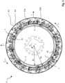
- Fig. 3 shows a plan view of the left front side 21 of the milling drum 1, according to the Fig. 1 viewing direction indicated by A.
- the bandage 2 is defined by an inner circumferential surface with a bandage inner radius Ri and an outer circumferential surface 22 with a bandage outer radius Ra.
- one drive disk 7 is present, which connects the bandage 2 to a rotary drive and/or to a suspension.
Landscapes
- Engineering & Computer Science (AREA)
- Mining & Mineral Resources (AREA)
- Mechanical Engineering (AREA)
- Architecture (AREA)
- Civil Engineering (AREA)
- Structural Engineering (AREA)
- Road Repair (AREA)
- Milling Processes (AREA)
- Shovels (AREA)
Claims (2)
- Tambour de fraisage (1) pour une machine de fraisage de sol permettant de broyer et/ou d'enlever un matériau de sol, comportant une bande (2) cylindrique creuse s'étendant axialement dans le sens de la longueur, sur la surface périphérique extérieure (22) de laquelle sont disposés plusieurs pics de fraisage (3, 4) interchangeables permettant de broyer et/ou d'enlever le matériau de sol, lesquels pics de fraisage sont fixés à la bande (2) au moyen de moyens de maintien de pics interchangeables (31, 41), dans lequel deux pics de fraisage frontaux (5a ; 5b) font saillie (x), au niveau de la bande (2) cylindrique creuse dans la zone d'au moins une face frontale (21) de la bande (2) cylindrique creuse, par rapport à ladite face frontale (21),dans lequel les deux pics de fraisage frontaux (5a ; 5b) sont disposés directement dans la bande (2) sur la face frontale (21) concernée dans respectivement une poche (6a, 6b) et sont prévus pour, dans le mode de fraisage, découper au moins partiellement librement la zone de collision (T) entre ladite face frontale (21) et le matériau de sol à travailler, dans lequel les deux pics de fraisage frontaux (5a, 5b) sont réalisés sous forme de pics de fraisage interchangeables qui sont fixés à la bande (2) au moyen de moyens de maintien de pics interchangeables (51), dans lequel le premier des deux pics de fraisage frontaux (5a) est disposé dans la direction radiale (r) à peu près au milieu entre la surface périphérique intérieure et la surface périphérique extérieure (22) de la bande (2) cylindrique creuse, dans lequel le cercle de coupe (K5a) produit par ledit premier pic de fraisage frontal est situé à peu près au milieu de la face frontale en forme d'anneau de cercle de la bande (2) cylindrique creuse,caractérisé en ceque le premier pic de fraisage frontal (5a) est disposé, conjointement avec son moyen de maintien de pic interchangeable (51) associé, directement dans la bande (2), une poche (6a) correspondante est usinée à cet effet dans la bande (2), dans laquelle poche le moyen de maintien de pic interchangeable (51) est soudé, dans lequel la poche (6a) traverse toute l'épaisseur de la bande (2), en ce que le second des deux pics de fraisage frontaux (5b) est disposé,
conjointement avec son moyen de maintien de pic interchangeable (51) correspondant, directement dans la bande (2), une poche (6b) correspondante est usinée à cet effet dans la bande (2), dans laquelle poche le moyen de maintien de pic interchangeable (51) est soudé, dans lequel ladite poche (6b) ne traverse pas toute l'épaisseur de la bande (2), et dans lequel le cercle de coupe (K5b) produit par ledit second pic de fraisage (5b) se trouve de 5 à 15 mm radialement à l'extérieur de la surface périphérique extérieure (22) de la bande (2). - Machine de fraisage de sol comportant un poste de conduite ou machine de fraisage de sol à guidage manuel, comprenant au moins un tambour de fraisage (1) selon la revendication précédente.
Applications Claiming Priority (1)
| Application Number | Priority Date | Filing Date | Title |
|---|---|---|---|
| DE102010013983.1A DE102010013983B4 (de) | 2010-04-06 | 2010-04-06 | Fräswalze für eine Bodenfräsmaschine und Bodenfräsmaschine |
Publications (4)
| Publication Number | Publication Date |
|---|---|
| EP2374936A2 EP2374936A2 (fr) | 2011-10-12 |
| EP2374936A3 EP2374936A3 (fr) | 2014-08-20 |
| EP2374936B1 EP2374936B1 (fr) | 2018-10-17 |
| EP2374936B2 true EP2374936B2 (fr) | 2025-01-01 |
Family
ID=44260408
Family Applications (1)
| Application Number | Title | Priority Date | Filing Date |
|---|---|---|---|
| EP11002790.1A Active EP2374936B2 (fr) | 2010-04-06 | 2011-04-04 | Cylindre de fraisage pour une machine à fraiser le sol et machine à fraiser le sol |
Country Status (5)
| Country | Link |
|---|---|
| US (1) | US8672416B2 (fr) |
| EP (1) | EP2374936B2 (fr) |
| CN (1) | CN102286913B (fr) |
| DE (2) | DE102010013983B4 (fr) |
| ES (1) | ES2706390T5 (fr) |
Families Citing this family (11)
| Publication number | Priority date | Publication date | Assignee | Title |
|---|---|---|---|---|
| DE102012203649A1 (de) * | 2012-03-08 | 2013-09-12 | Wirtgen Gmbh | Selbstfahrende Straßenfräsmaschine zum Bearbeiten von Straßenoberflächen, insbesondere Großfräse |
| DE102014001921B4 (de) | 2013-02-22 | 2024-08-22 | Bomag Gmbh | Fräswalze mit einer, insbesondere austauschbaren, Materialleiteinrichtung |
| CN103276658A (zh) * | 2013-05-24 | 2013-09-04 | 广西玉柴重工有限公司 | 一种铣刨装置 |
| WO2015073821A1 (fr) | 2013-11-15 | 2015-05-21 | Vermeer Manufacturing Company | Système de dents coupantes |
| DE102014015584B4 (de) * | 2014-10-21 | 2018-10-25 | Bomag Gmbh | Fräswalze und Bodenfräsmaschine mit derartiger Fräswalze |
| AU2015346526A1 (en) * | 2014-11-10 | 2017-06-01 | Vermeer Manufacturing Company | Edge cutting element for rotatable cutting drum |
| USD896289S1 (en) * | 2018-07-10 | 2020-09-15 | Bomag Gmbh | Quick-change toolholder |
| CN110952428A (zh) * | 2019-12-02 | 2020-04-03 | 上海道基环保科技有限公司 | 一种用于重型机械刀鼓的刀头及其磨损状态报警系统 |
| DE102019135867A1 (de) | 2019-12-30 | 2021-07-01 | Wirtgen Gmbh | Abtragendes Bodenbearbeitungsverfahren mit bezüglich der Vortriebsrichtung schräg angestelltem abtragendem Werkzeug und zur Ausführung des Verfahrens ausgebildete Bodenbearbeitungsmaschine |
| CN114737456B (zh) * | 2022-05-06 | 2023-08-01 | 江苏徐工工程机械研究院有限公司 | 铣刨转子和铣刨机 |
| US12618205B2 (en) | 2023-04-03 | 2026-05-05 | Graco Minnesota Inc. | Pavement grinding drum having modular bit mountings |
Family Cites Families (17)
| Publication number | Priority date | Publication date | Assignee | Title |
|---|---|---|---|---|
| DE1164450B (de) | 1959-04-10 | 1964-03-05 | Henry Neuenburg | Strassenfraesmaschine zum Herstellen von Ausnehmungen fuer Markierungsstreifen |
| US5775781A (en) * | 1996-01-26 | 1998-07-07 | Randy R. Sawtelle | Pavement marking removal tool and method |
| DE29613658U1 (de) | 1996-08-07 | 1996-10-02 | Bacher, Manfred, 88276 Berg | Maschine zum Abfräsen von Bodenflächen aus Beton und Fräswalze hierfür |
| US5884979A (en) * | 1997-04-17 | 1999-03-23 | Keystone Engineering & Manufacturing Corporation | Cutting bit holder and support surface |
| IT1292984B1 (it) | 1997-04-28 | 1999-02-11 | Bitelli Spa | Tamburo fresante di tipo perfezionato per macchine scarificatrici. |
| FI107629B (fi) * | 1997-10-02 | 2001-09-14 | Ideachip Oy | Menetelmä maa-ainesten sekoittamiseksi |
| AUPP764598A0 (en) * | 1998-12-11 | 1999-01-14 | R N Cribb Pty Limited | Rotary drum cutting head |
| DE10132608B4 (de) * | 2001-07-05 | 2006-02-02 | Firma Klaus Ertmer Maschinenbautechnologie | Aktivierungsgerät und Aktivierungssystem zur Bereitstellung eines Schlagimpulses für Schneidköpfe hydraulischer Trägergeräte |
| ITBO20010632A1 (it) * | 2001-10-16 | 2003-04-16 | Simex Engineering S R L | Fresatrice oleodinamica per macchine escavatrici |
| DE10202536A1 (de) * | 2002-01-24 | 2003-08-21 | Juergen Schenk | Fräseinrichtung für Boden, Fels, Aushub oder anderes Material |
| US7066555B2 (en) * | 2003-08-26 | 2006-06-27 | Asphalt Zipper, Inc. | Reinforced concrete milling/cutting mandrel |
| US7204442B2 (en) * | 2004-01-13 | 2007-04-17 | Vermeer Manufacturing Company | Apparatus and method for supporting and retaining a hammer and cutter |
| AT8148U1 (de) * | 2004-05-10 | 2006-02-15 | Voest Alpine Bergtechnik | Schräm- oder schneidwalze |
| US7475949B2 (en) * | 2006-11-13 | 2009-01-13 | Kennametal Inc. | Edge cutter assembly for use with a rotatable drum |
| US7976238B2 (en) * | 2006-12-01 | 2011-07-12 | Hall David R | End of a moldboard positioned proximate a milling drum |
| US7604301B1 (en) * | 2006-12-07 | 2009-10-20 | Lang William J | Dual axis grinder blender |
| DE102008016673B4 (de) * | 2008-03-26 | 2014-05-15 | Allu Deutschland Gmbh | Vorrichtung zum Fräsen und Mischen von Böden |
-
2010
- 2010-04-06 DE DE102010013983.1A patent/DE102010013983B4/de active Active
- 2010-04-06 DE DE202010018288.3U patent/DE202010018288U1/de not_active Expired - Lifetime
-
2011
- 2011-04-04 EP EP11002790.1A patent/EP2374936B2/fr active Active
- 2011-04-04 ES ES11002790T patent/ES2706390T5/es active Active
- 2011-04-04 US US13/079,407 patent/US8672416B2/en not_active Expired - Fee Related
- 2011-04-06 CN CN201110162940.7A patent/CN102286913B/zh active Active
Non-Patent Citations (3)
| Title |
|---|
| offenkundige Vörbehützühg OVB1 † |
| OV-B1 1 bis OVB1-6 technische Zeichnungen † |
| OVB1-11 OVB1-12 Fotos † |
Also Published As
| Publication number | Publication date |
|---|---|
| CN102286913B (zh) | 2015-11-25 |
| DE202010018288U1 (de) | 2015-08-03 |
| ES2706390T5 (en) | 2025-04-24 |
| EP2374936A2 (fr) | 2011-10-12 |
| EP2374936B1 (fr) | 2018-10-17 |
| US8672416B2 (en) | 2014-03-18 |
| ES2706390T3 (es) | 2019-03-28 |
| EP2374936A3 (fr) | 2014-08-20 |
| DE102010013983B4 (de) | 2016-01-21 |
| DE102010013983A1 (de) | 2011-10-06 |
| CN102286913A (zh) | 2011-12-21 |
| US20110241408A1 (en) | 2011-10-06 |
Similar Documents
| Publication | Publication Date | Title |
|---|---|---|
| EP2374936B1 (fr) | Cylindre de fraisage pour une machine à fraiser le sol et machine à fraiser le sol | |
| EP2685007B1 (fr) | Cutting wheel for a slotted wall cutter | |
| DE69805566T2 (de) | Meisselhalter und Stützfläche | |
| EP0281997B1 (fr) | Fleuret à rocher | |
| EP3346057B1 (fr) | Rouleau de travail du sol | |
| EP1780375B1 (fr) | Dent de fraisage d'un dispositif pour travailler la terre | |
| EP2479344A1 (fr) | Caisson de rotor pour une machine à fraiser le sol dotée d'un dispositif de guidage pour des produits de fraisage et machine à fraiser le sol dotée d'un tel caisson de rotor | |
| DE2629284C3 (de) | Fräsmaschine zur Bankett-, Graben- und Böschungsreinigung | |
| EP2374544B1 (fr) | Dispositif de broyage de matériaux compostables | |
| EP3159086A1 (fr) | Outil de forage | |
| DE10336616B4 (de) | Auswechselbarer Schneideeinsatz und mit dem Schneideeinsatz ausgestattetes Drehschneidewerkzeug | |
| EP2843134A1 (fr) | Système de support interchangeable pour un rouleau de compactage et un rouleau compresseur | |
| DE102010064589A1 (de) | Fräswalze für eine Bodenfräsmaschine und Bodenfräsmaschine | |
| EP3339568A1 (fr) | Outil de démolition et procédé de démolition de roche | |
| DE202011051765U1 (de) | Verschleißwerkzeug für eine Zerkleinerungsmaschine | |
| EP2374543A2 (fr) | Plaque de découpe pour un dispositif de broyage de matériau compostable | |
| DE29914056U1 (de) | Zerkleinerungsvorrichtung | |
| DE2821248C3 (de) | Gesteinsbohrkrone zum Drehschlagbohrer | |
| EP0607958A1 (fr) | Trépan de roche | |
| EP2789418B1 (fr) | Partie de coupe pour un foret | |
| EP1722186B1 (fr) | Fraise de déminage pour un véhicule de déminage. | |
| DE4431551A1 (de) | Brecher mit einem Gestell, indem ein angetriebener, steinbrechender Rotor gelagert ist | |
| EP2043817B1 (fr) | Meule | |
| DE102011054820A1 (de) | Verschleißwerkzeug für eine Zerkleinerungsmaschine | |
| WO2023016915A1 (fr) | Roue de coupe |
Legal Events
| Date | Code | Title | Description |
|---|---|---|---|
| PUAI | Public reference made under article 153(3) epc to a published international application that has entered the european phase |
Free format text: ORIGINAL CODE: 0009012 |
|
| AK | Designated contracting states |
Kind code of ref document: A2 Designated state(s): AL AT BE BG CH CY CZ DE DK EE ES FI FR GB GR HR HU IE IS IT LI LT LU LV MC MK MT NL NO PL PT RO RS SE SI SK SM TR |
|
| AX | Request for extension of the european patent |
Extension state: BA ME |
|
| PUAL | Search report despatched |
Free format text: ORIGINAL CODE: 0009013 |
|
| AK | Designated contracting states |
Kind code of ref document: A3 Designated state(s): AL AT BE BG CH CY CZ DE DK EE ES FI FR GB GR HR HU IE IS IT LI LT LU LV MC MK MT NL NO PL PT RO RS SE SI SK SM TR |
|
| AX | Request for extension of the european patent |
Extension state: BA ME |
|
| RIC1 | Information provided on ipc code assigned before grant |
Ipc: E01C 23/088 20060101AFI20140714BHEP Ipc: B28D 1/18 20060101ALI20140714BHEP |
|
| 17P | Request for examination filed |
Effective date: 20141028 |
|
| RBV | Designated contracting states (corrected) |
Designated state(s): AL AT BE BG CH CY CZ DE DK EE ES FI FR GB GR HR HU IE IS IT LI LT LU LV MC MK MT NL NO PL PT RO RS SE SI SK SM TR |
|
| 17Q | First examination report despatched |
Effective date: 20160105 |
|
| TPAC | Observations filed by third parties |
Free format text: ORIGINAL CODE: EPIDOSNTIPA |
|
| STAA | Information on the status of an ep patent application or granted ep patent |
Free format text: STATUS: EXAMINATION IS IN PROGRESS |
|
| TPAC | Observations filed by third parties |
Free format text: ORIGINAL CODE: EPIDOSNTIPA |
|
| GRAP | Despatch of communication of intention to grant a patent |
Free format text: ORIGINAL CODE: EPIDOSNIGR1 |
|
| STAA | Information on the status of an ep patent application or granted ep patent |
Free format text: STATUS: GRANT OF PATENT IS INTENDED |
|
| INTG | Intention to grant announced |
Effective date: 20180626 |
|
| GRAS | Grant fee paid |
Free format text: ORIGINAL CODE: EPIDOSNIGR3 |
|
| GRAA | (expected) grant |
Free format text: ORIGINAL CODE: 0009210 |
|
| STAA | Information on the status of an ep patent application or granted ep patent |
Free format text: STATUS: THE PATENT HAS BEEN GRANTED |
|
| AK | Designated contracting states |
Kind code of ref document: B1 Designated state(s): AL AT BE BG CH CY CZ DE DK EE ES FI FR GB GR HR HU IE IS IT LI LT LU LV MC MK MT NL NO PL PT RO RS SE SI SK SM TR |
|
| REG | Reference to a national code |
Ref country code: GB Ref legal event code: FG4D Free format text: NOT ENGLISH |
|
| REG | Reference to a national code |
Ref country code: CH Ref legal event code: EP |
|
| REG | Reference to a national code |
Ref country code: IE Ref legal event code: FG4D Free format text: LANGUAGE OF EP DOCUMENT: GERMAN |
|
| REG | Reference to a national code |
Ref country code: DE Ref legal event code: R096 Ref document number: 502011014852 Country of ref document: DE Ref country code: AT Ref legal event code: REF Ref document number: 1054193 Country of ref document: AT Kind code of ref document: T Effective date: 20181115 |
|
| REG | Reference to a national code |
Ref country code: NL Ref legal event code: MP Effective date: 20181017 |
|
| REG | Reference to a national code |
Ref country code: LT Ref legal event code: MG4D |
|
| REG | Reference to a national code |
Ref country code: ES Ref legal event code: FG2A Ref document number: 2706390 Country of ref document: ES Kind code of ref document: T3 Effective date: 20190328 |
|
| PG25 | Lapsed in a contracting state [announced via postgrant information from national office to epo] |
Ref country code: NL Free format text: LAPSE BECAUSE OF FAILURE TO SUBMIT A TRANSLATION OF THE DESCRIPTION OR TO PAY THE FEE WITHIN THE PRESCRIBED TIME-LIMIT Effective date: 20181017 |
|
| PG25 | Lapsed in a contracting state [announced via postgrant information from national office to epo] |
Ref country code: IS Free format text: LAPSE BECAUSE OF FAILURE TO SUBMIT A TRANSLATION OF THE DESCRIPTION OR TO PAY THE FEE WITHIN THE PRESCRIBED TIME-LIMIT Effective date: 20190217 Ref country code: NO Free format text: LAPSE BECAUSE OF FAILURE TO SUBMIT A TRANSLATION OF THE DESCRIPTION OR TO PAY THE FEE WITHIN THE PRESCRIBED TIME-LIMIT Effective date: 20190117 Ref country code: PL Free format text: LAPSE BECAUSE OF FAILURE TO SUBMIT A TRANSLATION OF THE DESCRIPTION OR TO PAY THE FEE WITHIN THE PRESCRIBED TIME-LIMIT Effective date: 20181017 Ref country code: BG Free format text: LAPSE BECAUSE OF FAILURE TO SUBMIT A TRANSLATION OF THE DESCRIPTION OR TO PAY THE FEE WITHIN THE PRESCRIBED TIME-LIMIT Effective date: 20190117 Ref country code: LT Free format text: LAPSE BECAUSE OF FAILURE TO SUBMIT A TRANSLATION OF THE DESCRIPTION OR TO PAY THE FEE WITHIN THE PRESCRIBED TIME-LIMIT Effective date: 20181017 Ref country code: FI Free format text: LAPSE BECAUSE OF FAILURE TO SUBMIT A TRANSLATION OF THE DESCRIPTION OR TO PAY THE FEE WITHIN THE PRESCRIBED TIME-LIMIT Effective date: 20181017 Ref country code: LV Free format text: LAPSE BECAUSE OF FAILURE TO SUBMIT A TRANSLATION OF THE DESCRIPTION OR TO PAY THE FEE WITHIN THE PRESCRIBED TIME-LIMIT Effective date: 20181017 Ref country code: HR Free format text: LAPSE BECAUSE OF FAILURE TO SUBMIT A TRANSLATION OF THE DESCRIPTION OR TO PAY THE FEE WITHIN THE PRESCRIBED TIME-LIMIT Effective date: 20181017 |
|
| PG25 | Lapsed in a contracting state [announced via postgrant information from national office to epo] |
Ref country code: SE Free format text: LAPSE BECAUSE OF FAILURE TO SUBMIT A TRANSLATION OF THE DESCRIPTION OR TO PAY THE FEE WITHIN THE PRESCRIBED TIME-LIMIT Effective date: 20181017 Ref country code: AL Free format text: LAPSE BECAUSE OF FAILURE TO SUBMIT A TRANSLATION OF THE DESCRIPTION OR TO PAY THE FEE WITHIN THE PRESCRIBED TIME-LIMIT Effective date: 20181017 Ref country code: PT Free format text: LAPSE BECAUSE OF FAILURE TO SUBMIT A TRANSLATION OF THE DESCRIPTION OR TO PAY THE FEE WITHIN THE PRESCRIBED TIME-LIMIT Effective date: 20190217 Ref country code: GR Free format text: LAPSE BECAUSE OF FAILURE TO SUBMIT A TRANSLATION OF THE DESCRIPTION OR TO PAY THE FEE WITHIN THE PRESCRIBED TIME-LIMIT Effective date: 20190118 Ref country code: RS Free format text: LAPSE BECAUSE OF FAILURE TO SUBMIT A TRANSLATION OF THE DESCRIPTION OR TO PAY THE FEE WITHIN THE PRESCRIBED TIME-LIMIT Effective date: 20181017 |
|
| REG | Reference to a national code |
Ref country code: DE Ref legal event code: R026 Ref document number: 502011014852 Country of ref document: DE |
|
| PLBI | Opposition filed |
Free format text: ORIGINAL CODE: 0009260 |
|
| PLAX | Notice of opposition and request to file observation + time limit sent |
Free format text: ORIGINAL CODE: EPIDOSNOBS2 |
|
| PG25 | Lapsed in a contracting state [announced via postgrant information from national office to epo] |
Ref country code: CZ Free format text: LAPSE BECAUSE OF FAILURE TO SUBMIT A TRANSLATION OF THE DESCRIPTION OR TO PAY THE FEE WITHIN THE PRESCRIBED TIME-LIMIT Effective date: 20181017 Ref country code: IT Free format text: LAPSE BECAUSE OF FAILURE TO SUBMIT A TRANSLATION OF THE DESCRIPTION OR TO PAY THE FEE WITHIN THE PRESCRIBED TIME-LIMIT Effective date: 20181017 Ref country code: DK Free format text: LAPSE BECAUSE OF FAILURE TO SUBMIT A TRANSLATION OF THE DESCRIPTION OR TO PAY THE FEE WITHIN THE PRESCRIBED TIME-LIMIT Effective date: 20181017 |
|
| 26 | Opposition filed |
Opponent name: WIRTGEN GMBH Effective date: 20190716 |
|
| PG25 | Lapsed in a contracting state [announced via postgrant information from national office to epo] |
Ref country code: SM Free format text: LAPSE BECAUSE OF FAILURE TO SUBMIT A TRANSLATION OF THE DESCRIPTION OR TO PAY THE FEE WITHIN THE PRESCRIBED TIME-LIMIT Effective date: 20181017 Ref country code: RO Free format text: LAPSE BECAUSE OF FAILURE TO SUBMIT A TRANSLATION OF THE DESCRIPTION OR TO PAY THE FEE WITHIN THE PRESCRIBED TIME-LIMIT Effective date: 20181017 Ref country code: EE Free format text: LAPSE BECAUSE OF FAILURE TO SUBMIT A TRANSLATION OF THE DESCRIPTION OR TO PAY THE FEE WITHIN THE PRESCRIBED TIME-LIMIT Effective date: 20181017 Ref country code: SK Free format text: LAPSE BECAUSE OF FAILURE TO SUBMIT A TRANSLATION OF THE DESCRIPTION OR TO PAY THE FEE WITHIN THE PRESCRIBED TIME-LIMIT Effective date: 20181017 |
|
| PG25 | Lapsed in a contracting state [announced via postgrant information from national office to epo] |
Ref country code: SI Free format text: LAPSE BECAUSE OF FAILURE TO SUBMIT A TRANSLATION OF THE DESCRIPTION OR TO PAY THE FEE WITHIN THE PRESCRIBED TIME-LIMIT Effective date: 20181017 |
|
| REG | Reference to a national code |
Ref country code: CH Ref legal event code: PL |
|
| PLBB | Reply of patent proprietor to notice(s) of opposition received |
Free format text: ORIGINAL CODE: EPIDOSNOBS3 |
|
| REG | Reference to a national code |
Ref country code: BE Ref legal event code: MM Effective date: 20190430 |
|
| PG25 | Lapsed in a contracting state [announced via postgrant information from national office to epo] |
Ref country code: LU Free format text: LAPSE BECAUSE OF NON-PAYMENT OF DUE FEES Effective date: 20190404 Ref country code: MC Free format text: LAPSE BECAUSE OF FAILURE TO SUBMIT A TRANSLATION OF THE DESCRIPTION OR TO PAY THE FEE WITHIN THE PRESCRIBED TIME-LIMIT Effective date: 20181017 |
|
| PG25 | Lapsed in a contracting state [announced via postgrant information from national office to epo] |
Ref country code: LI Free format text: LAPSE BECAUSE OF NON-PAYMENT OF DUE FEES Effective date: 20190430 Ref country code: CH Free format text: LAPSE BECAUSE OF NON-PAYMENT OF DUE FEES Effective date: 20190430 |
|
| PG25 | Lapsed in a contracting state [announced via postgrant information from national office to epo] |
Ref country code: BE Free format text: LAPSE BECAUSE OF NON-PAYMENT OF DUE FEES Effective date: 20190430 |
|
| PG25 | Lapsed in a contracting state [announced via postgrant information from national office to epo] |
Ref country code: TR Free format text: LAPSE BECAUSE OF FAILURE TO SUBMIT A TRANSLATION OF THE DESCRIPTION OR TO PAY THE FEE WITHIN THE PRESCRIBED TIME-LIMIT Effective date: 20181017 |
|
| PG25 | Lapsed in a contracting state [announced via postgrant information from national office to epo] |
Ref country code: IE Free format text: LAPSE BECAUSE OF NON-PAYMENT OF DUE FEES Effective date: 20190404 |
|
| REG | Reference to a national code |
Ref country code: AT Ref legal event code: MM01 Ref document number: 1054193 Country of ref document: AT Kind code of ref document: T Effective date: 20190404 |
|
| PG25 | Lapsed in a contracting state [announced via postgrant information from national office to epo] |
Ref country code: AT Free format text: LAPSE BECAUSE OF NON-PAYMENT OF DUE FEES Effective date: 20190404 |
|
| PG25 | Lapsed in a contracting state [announced via postgrant information from national office to epo] |
Ref country code: CY Free format text: LAPSE BECAUSE OF FAILURE TO SUBMIT A TRANSLATION OF THE DESCRIPTION OR TO PAY THE FEE WITHIN THE PRESCRIBED TIME-LIMIT Effective date: 20181017 |
|
| PG25 | Lapsed in a contracting state [announced via postgrant information from national office to epo] |
Ref country code: MT Free format text: LAPSE BECAUSE OF FAILURE TO SUBMIT A TRANSLATION OF THE DESCRIPTION OR TO PAY THE FEE WITHIN THE PRESCRIBED TIME-LIMIT Effective date: 20181017 Ref country code: HU Free format text: LAPSE BECAUSE OF FAILURE TO SUBMIT A TRANSLATION OF THE DESCRIPTION OR TO PAY THE FEE WITHIN THE PRESCRIBED TIME-LIMIT; INVALID AB INITIO Effective date: 20110404 |
|
| APBM | Appeal reference recorded |
Free format text: ORIGINAL CODE: EPIDOSNREFNO |
|
| APBP | Date of receipt of notice of appeal recorded |
Free format text: ORIGINAL CODE: EPIDOSNNOA2O |
|
| APAH | Appeal reference modified |
Free format text: ORIGINAL CODE: EPIDOSCREFNO |
|
| APBQ | Date of receipt of statement of grounds of appeal recorded |
Free format text: ORIGINAL CODE: EPIDOSNNOA3O |
|
| PG25 | Lapsed in a contracting state [announced via postgrant information from national office to epo] |
Ref country code: MK Free format text: LAPSE BECAUSE OF FAILURE TO SUBMIT A TRANSLATION OF THE DESCRIPTION OR TO PAY THE FEE WITHIN THE PRESCRIBED TIME-LIMIT Effective date: 20181017 |
|
| APAH | Appeal reference modified |
Free format text: ORIGINAL CODE: EPIDOSCREFNO |
|
| P01 | Opt-out of the competence of the unified patent court (upc) registered |
Effective date: 20230527 |
|
| REG | Reference to a national code |
Ref country code: DE Ref legal event code: R082 Ref document number: 502011014852 Country of ref document: DE Representative=s name: ZIMMERMANN & PARTNER PATENTANWAELTE MBB, DE |
|
| APBU | Appeal procedure closed |
Free format text: ORIGINAL CODE: EPIDOSNNOA9O |
|
| PUAH | Patent maintained in amended form |
Free format text: ORIGINAL CODE: 0009272 |
|
| STAA | Information on the status of an ep patent application or granted ep patent |
Free format text: STATUS: PATENT MAINTAINED AS AMENDED |
|
| 27A | Patent maintained in amended form |
Effective date: 20250101 |
|
| AK | Designated contracting states |
Kind code of ref document: B2 Designated state(s): AL AT BE BG CH CY CZ DE DK EE ES FI FR GB GR HR HU IE IS IT LI LT LU LV MC MK MT NL NO PL PT RO RS SE SI SK SM TR |
|
| REG | Reference to a national code |
Ref country code: DE Ref legal event code: R102 Ref document number: 502011014852 Country of ref document: DE |
|
| REG | Reference to a national code |
Ref country code: ES Ref legal event code: DC2A Ref document number: 2706390 Country of ref document: ES Kind code of ref document: T5 Effective date: 20250424 |
|
| PGFP | Annual fee paid to national office [announced via postgrant information from national office to epo] |
Ref country code: DE Payment date: 20250417 Year of fee payment: 15 |
|
| PGFP | Annual fee paid to national office [announced via postgrant information from national office to epo] |
Ref country code: GB Payment date: 20250423 Year of fee payment: 15 Ref country code: ES Payment date: 20250519 Year of fee payment: 15 |
|
| PGFP | Annual fee paid to national office [announced via postgrant information from national office to epo] |
Ref country code: FR Payment date: 20250422 Year of fee payment: 15 |