EP2375018A2 - Wabenstrukturkörper und Abgasumwandlungsvorrichtung - Google Patents
Wabenstrukturkörper und Abgasumwandlungsvorrichtung Download PDFInfo
- Publication number
- EP2375018A2 EP2375018A2 EP11153500A EP11153500A EP2375018A2 EP 2375018 A2 EP2375018 A2 EP 2375018A2 EP 11153500 A EP11153500 A EP 11153500A EP 11153500 A EP11153500 A EP 11153500A EP 2375018 A2 EP2375018 A2 EP 2375018A2
- Authority
- EP
- European Patent Office
- Prior art keywords
- honeycomb
- structural body
- electrodes
- honeycomb structural
- honeycomb unit
- Prior art date
- Legal status (The legal status is an assumption and is not a legal conclusion. Google has not performed a legal analysis and makes no representation as to the accuracy of the status listed.)
- Withdrawn
Links
Images

Classifications
-
- F—MECHANICAL ENGINEERING; LIGHTING; HEATING; WEAPONS; BLASTING
- F01—MACHINES OR ENGINES IN GENERAL; ENGINE PLANTS IN GENERAL; STEAM ENGINES
- F01N—GAS-FLOW SILENCERS OR EXHAUST APPARATUS FOR MACHINES OR ENGINES IN GENERAL; GAS-FLOW SILENCERS OR EXHAUST APPARATUS FOR INTERNAL-COMBUSTION ENGINES
- F01N3/00—Exhaust or silencing apparatus having means for purifying, rendering innocuous, or otherwise treating exhaust
- F01N3/02—Exhaust or silencing apparatus having means for purifying, rendering innocuous, or otherwise treating exhaust for cooling, or for removing solid constituents of, exhaust
- F01N3/021—Exhaust or silencing apparatus having means for purifying, rendering innocuous, or otherwise treating exhaust for cooling, or for removing solid constituents of, exhaust by means of filters
- F01N3/023—Exhaust or silencing apparatus having means for purifying, rendering innocuous, or otherwise treating exhaust for cooling, or for removing solid constituents of, exhaust by means of filters using means for regenerating the filters, e.g. by burning trapped particles
- F01N3/027—Exhaust or silencing apparatus having means for purifying, rendering innocuous, or otherwise treating exhaust for cooling, or for removing solid constituents of, exhaust by means of filters using means for regenerating the filters, e.g. by burning trapped particles using electric or magnetic heating means
- F01N3/0275—Exhaust or silencing apparatus having means for purifying, rendering innocuous, or otherwise treating exhaust for cooling, or for removing solid constituents of, exhaust by means of filters using means for regenerating the filters, e.g. by burning trapped particles using electric or magnetic heating means using electric discharge means
-
- B—PERFORMING OPERATIONS; TRANSPORTING
- B03—SEPARATION OF SOLID MATERIALS USING LIQUIDS OR USING PNEUMATIC TABLES OR JIGS; MAGNETIC OR ELECTROSTATIC SEPARATION OF SOLID MATERIALS FROM SOLID MATERIALS OR FLUIDS; SEPARATION BY HIGH-VOLTAGE ELECTRIC FIELDS
- B03C—MAGNETIC OR ELECTROSTATIC SEPARATION OF SOLID MATERIALS FROM SOLID MATERIALS OR FLUIDS; SEPARATION BY HIGH-VOLTAGE ELECTRIC FIELDS
- B03C3/00—Separating dispersed particles from gases or vapour, e.g. air, by electrostatic effect
- B03C3/34—Constructional details or accessories or operation thereof
- B03C3/40—Electrode constructions
- B03C3/45—Collecting-electrodes
- B03C3/455—Collecting-electrodes specially adapted for heat exchange with the gas stream
-
- B—PERFORMING OPERATIONS; TRANSPORTING
- B03—SEPARATION OF SOLID MATERIALS USING LIQUIDS OR USING PNEUMATIC TABLES OR JIGS; MAGNETIC OR ELECTROSTATIC SEPARATION OF SOLID MATERIALS FROM SOLID MATERIALS OR FLUIDS; SEPARATION BY HIGH-VOLTAGE ELECTRIC FIELDS
- B03C—MAGNETIC OR ELECTROSTATIC SEPARATION OF SOLID MATERIALS FROM SOLID MATERIALS OR FLUIDS; SEPARATION BY HIGH-VOLTAGE ELECTRIC FIELDS
- B03C3/00—Separating dispersed particles from gases or vapour, e.g. air, by electrostatic effect
- B03C3/34—Constructional details or accessories or operation thereof
- B03C3/40—Electrode constructions
- B03C3/45—Collecting-electrodes
- B03C3/51—Catch- space electrodes, e.g. slotted-box form
-
- B—PERFORMING OPERATIONS; TRANSPORTING
- B03—SEPARATION OF SOLID MATERIALS USING LIQUIDS OR USING PNEUMATIC TABLES OR JIGS; MAGNETIC OR ELECTROSTATIC SEPARATION OF SOLID MATERIALS FROM SOLID MATERIALS OR FLUIDS; SEPARATION BY HIGH-VOLTAGE ELECTRIC FIELDS
- B03C—MAGNETIC OR ELECTROSTATIC SEPARATION OF SOLID MATERIALS FROM SOLID MATERIALS OR FLUIDS; SEPARATION BY HIGH-VOLTAGE ELECTRIC FIELDS
- B03C3/00—Separating dispersed particles from gases or vapour, e.g. air, by electrostatic effect
- B03C3/34—Constructional details or accessories or operation thereof
- B03C3/40—Electrode constructions
- B03C3/60—Use of special materials other than liquids
- B03C3/62—Use of special materials other than liquids ceramics
-
- C—CHEMISTRY; METALLURGY
- C04—CEMENTS; CONCRETE; ARTIFICIAL STONE; CERAMICS; REFRACTORIES
- C04B—LIME, MAGNESIA; SLAG; CEMENTS; COMPOSITIONS THEREOF, e.g. MORTARS, CONCRETE OR LIKE BUILDING MATERIALS; ARTIFICIAL STONE; CERAMICS; REFRACTORIES; TREATMENT OF NATURAL STONE
- C04B37/00—Joining burned ceramic articles with other burned ceramic articles or other articles by heating
- C04B37/003—Joining burned ceramic articles with other burned ceramic articles or other articles by heating by means of an interlayer consisting of a combination of materials selected from glass, or ceramic material with metals, metal oxides or metal salts
- C04B37/005—Joining burned ceramic articles with other burned ceramic articles or other articles by heating by means of an interlayer consisting of a combination of materials selected from glass, or ceramic material with metals, metal oxides or metal salts consisting of glass or ceramic material
-
- F—MECHANICAL ENGINEERING; LIGHTING; HEATING; WEAPONS; BLASTING
- F01—MACHINES OR ENGINES IN GENERAL; ENGINE PLANTS IN GENERAL; STEAM ENGINES
- F01N—GAS-FLOW SILENCERS OR EXHAUST APPARATUS FOR MACHINES OR ENGINES IN GENERAL; GAS-FLOW SILENCERS OR EXHAUST APPARATUS FOR INTERNAL-COMBUSTION ENGINES
- F01N3/00—Exhaust or silencing apparatus having means for purifying, rendering innocuous, or otherwise treating exhaust
- F01N3/02—Exhaust or silencing apparatus having means for purifying, rendering innocuous, or otherwise treating exhaust for cooling, or for removing solid constituents of, exhaust
- F01N3/021—Exhaust or silencing apparatus having means for purifying, rendering innocuous, or otherwise treating exhaust for cooling, or for removing solid constituents of, exhaust by means of filters
- F01N3/022—Exhaust or silencing apparatus having means for purifying, rendering innocuous, or otherwise treating exhaust for cooling, or for removing solid constituents of, exhaust by means of filters characterised by specially adapted filtering structure, e.g. honeycomb, mesh or fibrous
- F01N3/0222—Exhaust or silencing apparatus having means for purifying, rendering innocuous, or otherwise treating exhaust for cooling, or for removing solid constituents of, exhaust by means of filters characterised by specially adapted filtering structure, e.g. honeycomb, mesh or fibrous the structure being monolithic, e.g. honeycombs
-
- F—MECHANICAL ENGINEERING; LIGHTING; HEATING; WEAPONS; BLASTING
- F01—MACHINES OR ENGINES IN GENERAL; ENGINE PLANTS IN GENERAL; STEAM ENGINES
- F01N—GAS-FLOW SILENCERS OR EXHAUST APPARATUS FOR MACHINES OR ENGINES IN GENERAL; GAS-FLOW SILENCERS OR EXHAUST APPARATUS FOR INTERNAL-COMBUSTION ENGINES
- F01N3/00—Exhaust or silencing apparatus having means for purifying, rendering innocuous, or otherwise treating exhaust
- F01N3/02—Exhaust or silencing apparatus having means for purifying, rendering innocuous, or otherwise treating exhaust for cooling, or for removing solid constituents of, exhaust
- F01N3/021—Exhaust or silencing apparatus having means for purifying, rendering innocuous, or otherwise treating exhaust for cooling, or for removing solid constituents of, exhaust by means of filters
- F01N3/033—Exhaust or silencing apparatus having means for purifying, rendering innocuous, or otherwise treating exhaust for cooling, or for removing solid constituents of, exhaust by means of filters in combination with other devices
- F01N3/035—Exhaust or silencing apparatus having means for purifying, rendering innocuous, or otherwise treating exhaust for cooling, or for removing solid constituents of, exhaust by means of filters in combination with other devices with catalytic reactors
-
- F—MECHANICAL ENGINEERING; LIGHTING; HEATING; WEAPONS; BLASTING
- F01—MACHINES OR ENGINES IN GENERAL; ENGINE PLANTS IN GENERAL; STEAM ENGINES
- F01N—GAS-FLOW SILENCERS OR EXHAUST APPARATUS FOR MACHINES OR ENGINES IN GENERAL; GAS-FLOW SILENCERS OR EXHAUST APPARATUS FOR INTERNAL-COMBUSTION ENGINES
- F01N3/00—Exhaust or silencing apparatus having means for purifying, rendering innocuous, or otherwise treating exhaust
- F01N3/08—Exhaust or silencing apparatus having means for purifying, rendering innocuous, or otherwise treating exhaust for rendering innocuous
- F01N3/10—Exhaust or silencing apparatus having means for purifying, rendering innocuous, or otherwise treating exhaust for rendering innocuous by thermal or catalytic conversion of noxious components of exhaust
- F01N3/18—Exhaust or silencing apparatus having means for purifying, rendering innocuous, or otherwise treating exhaust for rendering innocuous by thermal or catalytic conversion of noxious components of exhaust characterised by methods of operation; Control
- F01N3/20—Exhaust or silencing apparatus having means for purifying, rendering innocuous, or otherwise treating exhaust for rendering innocuous by thermal or catalytic conversion of noxious components of exhaust characterised by methods of operation; Control specially adapted for catalytic conversion
- F01N3/2006—Periodically heating or cooling catalytic reactors, e.g. at cold starting or overheating
- F01N3/2013—Periodically heating or cooling catalytic reactors, e.g. at cold starting or overheating using electric or magnetic heating means
- F01N3/2026—Periodically heating or cooling catalytic reactors, e.g. at cold starting or overheating using electric or magnetic heating means directly electrifying the catalyst substrate, i.e. heating the electrically conductive catalyst substrate by joule effect
-
- F—MECHANICAL ENGINEERING; LIGHTING; HEATING; WEAPONS; BLASTING
- F01—MACHINES OR ENGINES IN GENERAL; ENGINE PLANTS IN GENERAL; STEAM ENGINES
- F01N—GAS-FLOW SILENCERS OR EXHAUST APPARATUS FOR MACHINES OR ENGINES IN GENERAL; GAS-FLOW SILENCERS OR EXHAUST APPARATUS FOR INTERNAL-COMBUSTION ENGINES
- F01N3/00—Exhaust or silencing apparatus having means for purifying, rendering innocuous, or otherwise treating exhaust
- F01N3/08—Exhaust or silencing apparatus having means for purifying, rendering innocuous, or otherwise treating exhaust for rendering innocuous
- F01N3/10—Exhaust or silencing apparatus having means for purifying, rendering innocuous, or otherwise treating exhaust for rendering innocuous by thermal or catalytic conversion of noxious components of exhaust
- F01N3/24—Exhaust or silencing apparatus having means for purifying, rendering innocuous, or otherwise treating exhaust for rendering innocuous by thermal or catalytic conversion of noxious components of exhaust characterised by constructional aspects of converting apparatus
- F01N3/28—Construction of catalytic reactors
- F01N3/2803—Construction of catalytic reactors characterised by structure, by material or by manufacturing of catalyst support
- F01N3/2825—Ceramics
- F01N3/2828—Ceramic multi-channel monoliths, e.g. honeycombs
-
- B—PERFORMING OPERATIONS; TRANSPORTING
- B01—PHYSICAL OR CHEMICAL PROCESSES OR APPARATUS IN GENERAL
- B01D—SEPARATION
- B01D53/00—Separation of gases or vapours; Recovering vapours of volatile solvents from gases; Chemical or biological purification of waste gases, e.g. engine exhaust gases, smoke, fumes, flue gases, aerosols
- B01D53/34—Chemical or biological purification of waste gases
- B01D53/92—Chemical or biological purification of waste gases of engine exhaust gases
- B01D53/94—Chemical or biological purification of waste gases of engine exhaust gases by catalytic processes
-
- B—PERFORMING OPERATIONS; TRANSPORTING
- B03—SEPARATION OF SOLID MATERIALS USING LIQUIDS OR USING PNEUMATIC TABLES OR JIGS; MAGNETIC OR ELECTROSTATIC SEPARATION OF SOLID MATERIALS FROM SOLID MATERIALS OR FLUIDS; SEPARATION BY HIGH-VOLTAGE ELECTRIC FIELDS
- B03C—MAGNETIC OR ELECTROSTATIC SEPARATION OF SOLID MATERIALS FROM SOLID MATERIALS OR FLUIDS; SEPARATION BY HIGH-VOLTAGE ELECTRIC FIELDS
- B03C2201/00—Details of magnetic or electrostatic separation
- B03C2201/30—Details of magnetic or electrostatic separation for use in or with vehicles
-
- C—CHEMISTRY; METALLURGY
- C04—CEMENTS; CONCRETE; ARTIFICIAL STONE; CERAMICS; REFRACTORIES
- C04B—LIME, MAGNESIA; SLAG; CEMENTS; COMPOSITIONS THEREOF, e.g. MORTARS, CONCRETE OR LIKE BUILDING MATERIALS; ARTIFICIAL STONE; CERAMICS; REFRACTORIES; TREATMENT OF NATURAL STONE
- C04B2235/00—Aspects relating to ceramic starting mixtures or sintered ceramic products
- C04B2235/02—Composition of constituents of the starting material or of secondary phases of the final product
- C04B2235/50—Constituents or additives of the starting mixture chosen for their shape or used because of their shape or their physical appearance
- C04B2235/52—Constituents or additives characterised by their shapes
- C04B2235/5208—Fibers
-
- C—CHEMISTRY; METALLURGY
- C04—CEMENTS; CONCRETE; ARTIFICIAL STONE; CERAMICS; REFRACTORIES
- C04B—LIME, MAGNESIA; SLAG; CEMENTS; COMPOSITIONS THEREOF, e.g. MORTARS, CONCRETE OR LIKE BUILDING MATERIALS; ARTIFICIAL STONE; CERAMICS; REFRACTORIES; TREATMENT OF NATURAL STONE
- C04B2237/00—Aspects relating to ceramic laminates or to joining of ceramic articles with other articles by heating
- C04B2237/02—Aspects relating to interlayers, e.g. used to join ceramic articles with other articles by heating
- C04B2237/04—Ceramic interlayers
- C04B2237/06—Oxidic interlayers
- C04B2237/062—Oxidic interlayers based on silica or silicates
-
- C—CHEMISTRY; METALLURGY
- C04—CEMENTS; CONCRETE; ARTIFICIAL STONE; CERAMICS; REFRACTORIES
- C04B—LIME, MAGNESIA; SLAG; CEMENTS; COMPOSITIONS THEREOF, e.g. MORTARS, CONCRETE OR LIKE BUILDING MATERIALS; ARTIFICIAL STONE; CERAMICS; REFRACTORIES; TREATMENT OF NATURAL STONE
- C04B2237/00—Aspects relating to ceramic laminates or to joining of ceramic articles with other articles by heating
- C04B2237/02—Aspects relating to interlayers, e.g. used to join ceramic articles with other articles by heating
- C04B2237/04—Ceramic interlayers
- C04B2237/06—Oxidic interlayers
- C04B2237/064—Oxidic interlayers based on alumina or aluminates
-
- C—CHEMISTRY; METALLURGY
- C04—CEMENTS; CONCRETE; ARTIFICIAL STONE; CERAMICS; REFRACTORIES
- C04B—LIME, MAGNESIA; SLAG; CEMENTS; COMPOSITIONS THEREOF, e.g. MORTARS, CONCRETE OR LIKE BUILDING MATERIALS; ARTIFICIAL STONE; CERAMICS; REFRACTORIES; TREATMENT OF NATURAL STONE
- C04B2237/00—Aspects relating to ceramic laminates or to joining of ceramic articles with other articles by heating
- C04B2237/02—Aspects relating to interlayers, e.g. used to join ceramic articles with other articles by heating
- C04B2237/04—Ceramic interlayers
- C04B2237/06—Oxidic interlayers
- C04B2237/068—Oxidic interlayers based on refractory oxides, e.g. zirconia
-
- C—CHEMISTRY; METALLURGY
- C04—CEMENTS; CONCRETE; ARTIFICIAL STONE; CERAMICS; REFRACTORIES
- C04B—LIME, MAGNESIA; SLAG; CEMENTS; COMPOSITIONS THEREOF, e.g. MORTARS, CONCRETE OR LIKE BUILDING MATERIALS; ARTIFICIAL STONE; CERAMICS; REFRACTORIES; TREATMENT OF NATURAL STONE
- C04B2237/00—Aspects relating to ceramic laminates or to joining of ceramic articles with other articles by heating
- C04B2237/30—Composition of layers of ceramic laminates or of ceramic or metallic articles to be joined by heating, e.g. Si substrates
- C04B2237/32—Ceramic
- C04B2237/36—Non-oxidic
- C04B2237/365—Silicon carbide
-
- F—MECHANICAL ENGINEERING; LIGHTING; HEATING; WEAPONS; BLASTING
- F01—MACHINES OR ENGINES IN GENERAL; ENGINE PLANTS IN GENERAL; STEAM ENGINES
- F01N—GAS-FLOW SILENCERS OR EXHAUST APPARATUS FOR MACHINES OR ENGINES IN GENERAL; GAS-FLOW SILENCERS OR EXHAUST APPARATUS FOR INTERNAL-COMBUSTION ENGINES
- F01N2370/00—Selection of materials for exhaust purification
- F01N2370/02—Selection of materials for exhaust purification used in catalytic reactors
- F01N2370/04—Zeolitic material
-
- F—MECHANICAL ENGINEERING; LIGHTING; HEATING; WEAPONS; BLASTING
- F01—MACHINES OR ENGINES IN GENERAL; ENGINE PLANTS IN GENERAL; STEAM ENGINES
- F01N—GAS-FLOW SILENCERS OR EXHAUST APPARATUS FOR MACHINES OR ENGINES IN GENERAL; GAS-FLOW SILENCERS OR EXHAUST APPARATUS FOR INTERNAL-COMBUSTION ENGINES
- F01N2450/00—Methods or apparatus for fitting, inserting or repairing different elements
- F01N2450/28—Methods or apparatus for fitting, inserting or repairing different elements by using adhesive material, e.g. cement
-
- Y—GENERAL TAGGING OF NEW TECHNOLOGICAL DEVELOPMENTS; GENERAL TAGGING OF CROSS-SECTIONAL TECHNOLOGIES SPANNING OVER SEVERAL SECTIONS OF THE IPC; TECHNICAL SUBJECTS COVERED BY FORMER USPC CROSS-REFERENCE ART COLLECTIONS [XRACs] AND DIGESTS
- Y02—TECHNOLOGIES OR APPLICATIONS FOR MITIGATION OR ADAPTATION AGAINST CLIMATE CHANGE
- Y02T—CLIMATE CHANGE MITIGATION TECHNOLOGIES RELATED TO TRANSPORTATION
- Y02T10/00—Road transport of goods or passengers
- Y02T10/10—Internal combustion engine [ICE] based vehicles
- Y02T10/12—Improving ICE efficiencies
Definitions
- the present invention relates to a honeycomb structural body and an exhaust gas conversion apparatus.
- Exhaust gas of automobiles contain substances such as hydrocarbon compounds, carbon monoxide, and nitrogen oxide.
- a honeycomb structural body formed of cordierite is used for converting the exhaust gas.
- the honeycomb structural body includes plural through-holes partitioned by cell walls in which the surface of the cell walls is formed of a catalyst carrying layer formed of alumina. Catalysts such as platinum, rhodium, and palladium are carried on the catalyst carrying layer.
- Patent Document 2 discloses an exhaust gas filter for converting exhaust gas of an internal combustion engine in which the exhaust gas filter is formed of an assembly of plural porous ceramic filters and a pair of self-heating electrodes provided on both ends thereof.
- the conventional exhaust gas filter illustrated in Fig. 6 of Patent Document 2 includes a combination of a filter having a substantially quadrate cross section and a filter having a substantially isosceles triangle cross section and has a pair of self-heating electrodes on both ends of each of the filters. Accordingly, when canning the conventional exhaust gas filter to a metal pipe in a state where a holding sealing member is provided on the outer peripheral portion of the exhaust gas filter, the self-heating electrodes tends to disconnect due to the increasing contact pressure at the corner portions of the filter.
- an embodiment of the present invention aims to provide a honeycomb structural body capable of preventing disconnection of electrodes and locally adjusting the heating values at a center portion and an outer peripheral portion, and an exhaust gas conversion apparatus including the honeycomb structural body.
- a honeycomb structural body includes plural honeycomb units adhered to each other by interposing an adhesive layer, each of the plural honeycomb units having a plurality of through-holes arranged in a longitudinal direction thereof and containing a conductive ceramic material, wherein the honeycomb structural body has a circular-pillar shape or an elliptical-pillar shape, wherein the honeycomb unit has a fan-shaped or an elliptical fan-shaped cross section perpendicular to the longitudinal direction, wherein a pair of electrodes is formed at a part of an outer peripheral surface of the honeycomb unit that does not face the adhesive layer and an area between the honeycomb unit and the adhesive layer and/or formed at an area between the outer peripheral surface of the honeycomb unit and the adhesive layer and an area including a center of the fan-like shaped or the elliptical fan-like shaped cross section perpendicular to the longitudinal direction.
- the pair of electrodes is formed at an entire outer periphery of the honeycomb unit.
- the pair of electrodes is formed on both end portions of the honeycomb unit in the longitudinal direction.
- the distance between the pair of electrodes becomes shorter towards the center of the fan-like shaped or the elliptical fan-like shaped cross section.
- the fan-shaped or the elliptical fan-shaped cross section has a center angle of 90 degrees or less.
- each of the pair of electrodes is a belt-like electrode having a width ranging from 3 mm or more to 30 mm or less.
- the distance between the belt-like electrodes is adjusted so that the resistance between the belt-like electrodes is substantially equal.
- the pair of electrodes is formed by spaying or sputtering.
- the through-holes are partitioned by cell walls, wherein a catalyst is carried on the cell walls.
- the catalyst includes one or more of platinum, rhodium, and palladium.
- the conductive ceramic material contains silicon carbide.
- an exhaust gas conversion apparatus includes the above-mentioned honeycomb structural body according to the embodiment of the present invention.
- a honeycomb structural body capable of preventing disconnection of electrodes and adjusting the heating values at a center portion and an outer peripheral portion, and an exhaust gas conversion apparatus including the above-mentioned honeycomb structural body.
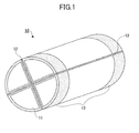
- Fig. 1 illustrates an example of a honeycomb structural body according to an embodiment of the present invention.
- the honeycomb structural body 10 has a circular-pillar shape and includes four pillar-shaped honeycomb units 11 adhered to each other by interposing an adhesive layer 12.
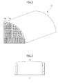
- Each honeycomb unit 11 includes plural square pillar-shaped through-holes 11a partitioned by cell walls 11b and arranged in a longitudinal direction of the honeycomb unit 11 (see Fig. 2 ).
- the cross section of the honeycomb unit being perpendicular to the longitudinal of the honeycomb unit 11, has a fan-like shape having a central angle of 90 degrees.
- the honeycomb unit 11 includes a conductive ceramic material.
- a pair of belt-like electrodes 13 is formed on the entire outer periphery of both end portions of each honeycomb unit 11 relative to the longitudinal direction of the honeycomb unit 11.
- the end portion of the honeycomb unit 11 includes the vicinity of the end portion of the honeycomb unit 11.
- the vicinity of the end portion of the honeycomb unit 11 refers to a distance of 30 mm or less from an end face of the honeycomb unit 11. Further, the outer peripheral surface does not include the end face.
- the pair of belt-like electrodes 13 is formed on an outer peripheral surface which does not face the adhesive layer 12 of the honeycomb unit 11. Further, the pair of belt-like electrodes is formed in a manner extending to an area between the honeycomb unit 11 and the adhesive layer 12. Further, the pair of belt-like electrodes is formed in an area between the outer peripheral surface of the honeycomb unit 11 and the adhesive layer 12. Further, the pair of belt-like electrodes is formed in an area including the center of the fan-like shaped cross section perpendicular to the longitudinal direction of the honeycomb unit 11.
- the center portion of the honeycomb unit 11 refers to a region towards the center of the fan-like shaped cross-section and an outer peripheral region refers to a region towards the outer periphery of the fan-like shaped cross-section in a case where the distance from the center of the fan-like shaped cross section to the outer periphery of the fan-like shaped cross section is equally divided into two regions.
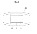
- the honeycomb structural body 10 has a circular-pillar shape, the contact pressure applied to the outer peripheral portion of each honeycomb unit 11 is equal in a case of canning the honeycomb structural body 10 to a metal pipe 30 in a state where a holding sealing member 20 is provided to the outer peripheral portion of the honeycomb structural body 10 (see Fig. 8 ). Accordingly, disconnection of the belt-like electrodes 13 can be prevented.
- the conductive ceramic material of the honeycomb unit 11 is not to be limited in particular as long as the honeycomb unit can sufficiently generate heat when predetermined current flows through the honeycomb unit 11, the conductive ceramic material may be, for example, a silicon carbide doped with aluminum nitride, aluminum, and the like.
- the resistance between the belt-like electrodes 13 of the honeycomb unit 11 is preferable for the resistance between the belt-like electrodes 13 of the honeycomb unit 11 to range from 1 ⁇ to 1 ⁇ 10 3 ⁇ . In a case where the resistance between the belt-like electrodes 13 of the honeycomb unit 11 is less than 1 ⁇ , the honeycomb unit 11 cannot sufficiently generate heat even if current is distributed through the honeycomb unit 11 according to Joule's law. On the other hand, in a case where the resistance between the belt-like electrodes 13 of the honeycomb unit 11 is more than 1 ⁇ 10 3 ⁇ , the current flowing in the honeycomb unit 11 becomes low even in a case where power is applied between the belt-like electrodes 13 from a high capacity battery used in, for example, a hybrid automobile. As a result, it becomes difficult to generate heat the honeycomb unit 11.
- the porosity of the honeycomb unit 11 can be measured by using a mercury penetration method.
- the cross section perpendicular to the longitudinal direction of the honeycomb unit 11 prefferably has an area ranging from 5 cm 2 to 50 cm 2 . In a case where the cross section perpendicular to the longitudinal direction of the honeycomb unit 11 has an area less than 5 cm 2 , the pressure loss of the honeycomb structural body 10 increases. On the other hand, in a case where the cross section perpendicular to the longitudinal direction of the honeycomb unit 11 has an area more than 50 cm 2 , the strength against thermal stress applied to the honeycomb unit 11 becomes insufficient.
- the cross-section perpendicular to the longitudinal direction of the honeycomb unit 11 prefferably has an opening ratio ranging from 50% to 85%. In a case where the cross-section perpendicular to the longitudinal direction of the honeycomb unit 11 has an opening ration less than 50%, the heat capacity of the honeycomb unit 11 increases. Thereby, it becomes difficult to generate heat the honeycomb unit 11. On the other hand, in a case where the cross-section perpendicular to the longitudinal direction of the honeycomb unit 11 has an opening ration more than 85%, the strength of the honeycomb unit 11 becomes insufficient.
- the cell walls 11b of the honeycomb unit 11 prefferably have a thickness ranging from 0.05 mm to 0.30 mm. In a case where the thickness of the cell walls 11b is less than 0.05 mm, the strength of the honeycomb unit 11 decreases. On the other hand, in a case where the thickness of the cell walls 11b is more than 0.30 mm, the thermal capacity of the honeycomb unit 11 increases. Thereby, it becomes difficult to generate heat the honeycomb unit 11.
- the catalyst carried on the cell walls 11b is not particularly limited in particular as long as exhaust gas can be converted.
- the catalyst may be, for example, platinum, rhodium, palladium and the like.
- a catalyst carrying layer containing ⁇ -alumina is formed on the surface of the cell walls 11b of the honeycomb unit 11. It is preferable for the catalyst to be carried on the catalyst carrying layer.
- the honeycomb unit 11 is formed of silicon carbide doped with aluminum nitride.
- the method for manufacturing the honeycomb unit 11 formed of silicon carbide doped with aluminum nitride is not limited in particular, the method may be, for example, baking a molded body molded by using a raw material paste containing silicon carbide and aluminum nitride.
- the content of the aluminum nitride in the raw material paste is preferable for the content of the aluminum nitride in the raw material paste to range from 0.1 mass% to 30 mass%.
- the raw material paste may further contain an organic binder, a dispersion medium, a molding auxiliary agent, or the like.
- the organic binder may include methyl cellulose, carboxymethyl cellulose, hydroxyethyl cellulose, polyethylene glycol, phenol resin, epoxy resin, or the like.
- the organic binder may include two or more of the methyl cellulose, carboxymethyl cellulose, hydroxyethyl cellulose, polyethylene glycol, phenol resin, epoxy resin, or the like.
- the content of the organic binder in the raw material paste is preferably 1 mass% to 10 mass% with respect to silicon carbide.
- the dispersion medium included in the raw material paste is not limited in particular, the dispersion medium may include water, an organic solvent (such as benzene), and alcohol (such as methanol), or the like.
- the dispersion medium may include two or more of water, an organic solvent (such as benzene), and alcohol (such as methanol), or the like.
- the method for molding the raw material paste is not limited in particular, the raw material paste may be subject to extrusion molding and the like.
- a drying apparatus for drying the molded body is not limited in particular, the drying apparatus may be a microwave drying apparatus, a hot-air drying apparatus, a dielectric drying apparatus, a pressure-reduction drying apparatus, a vacuum drying apparatus, a freeze drying apparatus, or the like.
- the dried molded body is preferably degreased, for example, at 400 °C for two hours.
- nitrogen may be added during the firing process, so that silicon carbide can be doped with the nitrogen.
- an alternative honeycomb unit having conductive material provided inside the pores of the base material (aggregate) of the alternative honeycomb unit may be used.
- the base material of the honeycomb unit is not limited in particular, the base material of the honeycomb unit 11 may be, for example, silicon carbide, aluminum titanate, cordierite, alumina, silica, zirconia, zeolite and the like.
- the method for manufacturing the base material of the honeycomb unit 11 formed of silicon carbide is not limited in particular, the method for manufacturing the base material of the honeycomb unit 11 may be, for example, a method using a raw material that does not contain aluminum nitride, or the like.
- the pores of the base material of the honeycomb unit 11 may include conductive material.
- the conductive material provided inside the pores of the base material of the honeycomb unit 11 is not limited in particular as long as the conductive material can be sufficiently generated heat when applied with power, the conductive material may be, for example, silicon, silicide such as nickel silicide, chrome silicide, iron silicide, or the like.
- a method for forming the conductive layer including silicon is not limited in particular, a method for forming the conductive layer including silicon may be, for example, a method that impregnates the surface of the base material of the honeycomb unit with a slurry containing a molten silicon, silicon, or a silicon precursor or the like.
- the center angle of the fan-like shaped cross section perpendicular to the longitudinal direction of the honeycomb unit 11 is not limited in particular as long as the center angle of the fan-like shaped cross section is 90 degrees or less.
- the center angle of the fan-like shaped cross section is preferably 75 degrees or less, and more preferably 60 degrees or less.
- the square-pillar shape of the through-holes 11a may be, for example, a triangular-pillar shape, a hexagonal-pillar shape and the like.
- the adhesive layer 12 of the honeycomb structured body 10 prefferably has a thickness ranging from 0.5 mm to 2 mm. In a case where the thickness of the adhesive layer 12 is less than 0.5 mm, adhesive strength between the honeycomb units 11 is insufficient. On the other hand, in a case where the thickness of the adhesive layer 12 is more than 2 mm, the pressure loss of the honeycomb structural body 10 increases.
- the method for adhering the honeycomb units 11 is not limited in particular, the method may be, for example, applying an adhesive-layer paste on the honeycomb unit 11 and then solidifying the applied adhesive-layer paste by drying, or the like.
- the adhesive-layer paste is not limited in particular, the adhesive-layer paste may be, for example, a mixture of an inorganic binder and inorganic particles, a mixture of an inorganic binder and inorganic fibers, a mixture of an inorganic binder, inorganic particles and inorganic fibers, or the like.
- the material of the inorganic fibers may be, for example, alumina, silica, silicon carbide, silica alumina, glass, potassium titanate, aluminum borate, and the like. These materials may be used singularly or used in combination. Among these materials, silica alumina is preferable.
- the inorganic particles contained in the adhesive-layer paste are not limited in particular, the material of the inorganic particles, may be, for example, silicon carbide, alumina, silica, titania, zirconia, ceria, mullite, and the like. These materials may be used singularly or used in combination. Among these materials, silicon carbide is preferable.
- the adhesive-layer paste may contain an organic binder.
- the material of the organic binder may be, for example, polyvinyl alcohol, methyl cellulose, ethyl cellulose, carboxylmethyl cellulose, and the like. These materials may be used singularly or used in combination.
- a honeycomb structural body 10 having an elliptical-pillar shape may be manufactured.
- the honeycomb structural body 10 substantially has the shape of a straight cylinder or an elliptical cylinder, i.e. a substantially straight cylinder having an ellipse as a base.
- the shape of the cross-section (perpendicular to the longitudinal direction of the honeycomb unit 11) of the honeycomb unit 11 of the honeycomb structural body 10 is an elliptical-like fan shape.
- the ellipse or the ellipse of the elliptical fan-like shape includes a track-like shape having two semi-circles formed by connecting two equal length lines. In other words, two semicylinders are connected.
- the fan-like shape can be described by a combination of plural parts of cylinders being connected with each other, each part having a part of a circle or an ellipse, for example, a half or a quarter of a circle or an ellipse as a base.
- the belt-like electrode 13 prefferably be formed of metal.
- the width of the belt-like electrodes 13 preferably ranges from 3 mm to 30 mm. In a case where the width of the belt-like electrodes 13 is less than 3 mm, the belt-like electrodes 13 are easily damaged when voltage is applied between the belt-like electrodes 13. In a case where the width of the belt-like electrodes 13 is more than 30 mm, the heating volume of the honeycomb unit 11 decreases when voltage is applied between the belt-like electrodes 13. Thereby, the honeycomb structural body 10 is unable to sufficiently convert exhaust gas.
- the method for forming the belt-like electrodes 13 is not limited in particular, the method may be, for example, spraying, sputtering or the like.
- the above-described belt-like electrodes 13 provided between the honeycomb unit 11 and the adhesive layer 12 are formed in a manner that the distance between a pair of belt-like electrodes 13 is constant with respect to the radial direction of the honeycomb structural body 10 (see Fig. 3 ).
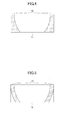
- the belt-like electrodes 13 may be formed in a manner that the distance between a pair of belt-like electrodes 13 becomes shorter the closer towards the center of the honeycomb structural body 10 (see Figs. 4 and 5 ). Thereby, the center portion of the honeycomb structural body 10 becomes easier to generate heat.
- Fig. 4 illustrates a case where the width of the belt-like electrodes 13 becomes larger towards the center of the honeycomb structural body 10
- Fig. 5 illustrates a case where the width of the belt-like electrodes 13 is constant with respect to the radial direction of the honeycomb structural body 10.
- Fig. 6 illustrates a modified example of a honeycomb structural body 10' according to an embodiment of the present invention.
- the honeycomb structural body 10' has belt-like electrodes 13' formed in a manner extending from a part of the outer peripheral surface of the honeycomb unit 11 which does not face the adhesive layer 12 to an area between the honeycomb unit 11 and the adhesive layer 12.
- the configuration of the honeycomb structural body 10' is the same as that of the honeycomb structural body 10 except for the belt-like electrodes 13'.
- the pair of the belt-like electrodes 13' is formed on the part of the outer peripheral surface of each honeycomb unit 11 which does not face the adhesive layer 12 and the area between the honeycomb unit 11 and the adhesive layer 12. Therefore, in a case where voltage is applied from an automobile battery to the four pairs of belt-like electrodes 13' via a pair of annular conductive materials electrically connected to the four pairs of belt-like electrodes 13', the current density of the current flowing in the outer peripheral portion of the honeycomb unit 11 can be higher than the current density of the current flowing in the center portion of the honeycomb unit 11. As a result, the heating value at the outer peripheral portion of the honeycomb unit 11 can be larger than the heating value at the center portion of the honeycomb unit 11.
- the temperature at the outer peripheral portion of the honeycomb unit 11 can be higher than the temperature at the center portion of the honeycomb unit 11. Even in a case of canning the honeycomb structural body 10' to the metal pipe 30 and using the honeycomb structural body 10' as an exhaust gas conversion apparatus in a state where a holding sealing member 20 is provided to the outer peripheral portion of the honeycomb structural body 10', the temperature at the outer peripheral portion of the honeycomb structural body 10' can be prevented from decreasing even if the heat insulation property of the holding sealing member 20 is insufficient.
- the temperature at the outer peripheral portion of the honeycomb structural body 10' can be prevented from decreasing even if the heat insulation property of the holding sealing member 20 is insufficient because an equal amount of voltage is applied to the four honeycomb units 11. Therefore, the temperature of the honeycomb structural body 10' is uniform and crack can be prevented from being prevented.
- the configuration of the belt-like electrodes 13' is the same as the configuration of the belt-like electrodes 13 except for the shape of the belt-like electrodes 13'.
- Fig. 7 illustrates a modified example of the honeycomb structural body 10 according to an embodiment of the present invention.
- the honeycomb structural body 10 instead of the belt-like electrodes 13, the honeycomb structural body 10" has belt-like electrodes 13" formed in an area between the outer peripheral surface of the honeycomb unit 11 and the adhesive layer 12 and an area including a center of the fan-shaped cross section perpendicular to the longitudinal direction of the honeycomb unit 11.
- the configuration of the honeycomb structural body 10" is the same as the configuration of the honeycomb structural body 10 except for the belt-like electrodes 13".
- the temperature at the center portion of the honeycomb unit 11 can be higher than the temperature at the outer peripheral portion of the honeycomb unit 11. Even in a case of canning the honeycomb structural body 10" to the metal pipe 30 and using the honeycomb structural body 10" as an exhaust gas conversion apparatus in a state where a holding sealing member 20 is provided to the outer peripheral portion of the honeycomb structural body 10", the temperature at the outer peripheral portion of the honeycomb structural body 10" easily decreases because the flow rate of exhaust gas becomes higher the closer towards the center portion of the honeycomb structural body 10" according to the principle of inertia. However, the temperature at the center portion of the honeycomb structural body 10" can be prevented from decreasing.
- the temperature at the center portion of the honeycomb structural body 10" can be prevented from decreasing because an equal amount of voltage is applied to the four honeycomb units 11. Therefore, the temperature of the honeycomb structural body 10" is uniform and the exhaust gas conversion property of the honeycomb structural body 10" can be prevented from degrading.
- the configuration of the belt-like electrodes 13" is the same as the configuration of the belt-like electrodes 13 except for the shape of the belt-like electrodes 13".
- the belt-like electrodes 13" may also be formed at a part of the outer peripheral surface of the honeycomb unit 11 which does not face the adhesive layer 12. Thereby, the belt-like electrodes 13" can be electrically connected to the annular conductive materials more easily.
Landscapes
- Engineering & Computer Science (AREA)
- Chemical & Material Sciences (AREA)
- Chemical Kinetics & Catalysis (AREA)
- Combustion & Propulsion (AREA)
- Mechanical Engineering (AREA)
- General Engineering & Computer Science (AREA)
- Ceramic Engineering (AREA)
- Health & Medical Sciences (AREA)
- Toxicology (AREA)
- Materials Engineering (AREA)
- Structural Engineering (AREA)
- Organic Chemistry (AREA)
- Catalysts (AREA)
- Exhaust Gas After Treatment (AREA)
- Exhaust Gas Treatment By Means Of Catalyst (AREA)
Applications Claiming Priority (1)
| Application Number | Priority Date | Filing Date | Title |
|---|---|---|---|
| PCT/JP2010/056479 WO2011125227A1 (ja) | 2010-04-09 | 2010-04-09 | ハニカム構造体及び排ガス浄化装置 |
Publications (2)
| Publication Number | Publication Date |
|---|---|
| EP2375018A2 true EP2375018A2 (de) | 2011-10-12 |
| EP2375018A3 EP2375018A3 (de) | 2013-05-15 |
Family
ID=44168446
Family Applications (1)
| Application Number | Title | Priority Date | Filing Date |
|---|---|---|---|
| EP11153500.1A Withdrawn EP2375018A3 (de) | 2010-04-09 | 2011-02-07 | Wabenstrukturkörper und Abgasumwandlungsvorrichtung |
Country Status (3)
| Country | Link |
|---|---|
| US (1) | US8506894B2 (de) |
| EP (1) | EP2375018A3 (de) |
| WO (1) | WO2011125227A1 (de) |
Cited By (5)
| Publication number | Priority date | Publication date | Assignee | Title |
|---|---|---|---|---|
| EP2689848A4 (de) * | 2011-03-25 | 2015-01-14 | Ngk Insulators Ltd | Wabenstruktur |
| EP2784284A3 (de) * | 2013-03-26 | 2015-08-19 | Ibiden Co., Ltd. | Haltedichtungsmaterial, Verfahren zur Herstellung des Haltedichtungsmaterial, Abgasreinigungsvorrichtung und Verfahren zur Herstellung einer Abgasreinigungsvorrichtung |
| CN106975351A (zh) * | 2017-04-28 | 2017-07-25 | 深圳市力德诺华科技有限公司 | 一种基于静电除尘技术和光催化技术的空气净化装置 |
| TWI648091B (zh) * | 2018-05-30 | 2019-01-21 | 仁美國際專利有限公司 | Method for manufacturing electric catalyst honeycomb for controlling exhaust gas emission |
| CN110284943A (zh) * | 2018-03-19 | 2019-09-27 | 日本碍子株式会社 | 蜂窝结构体 |
Families Citing this family (9)
| Publication number | Priority date | Publication date | Assignee | Title |
|---|---|---|---|---|
| WO2013047790A1 (ja) * | 2011-09-30 | 2013-04-04 | 日本碍子株式会社 | ハニカム構造体 |
| US9295944B2 (en) * | 2011-12-27 | 2016-03-29 | Toyota Jidosha Kabushiki Kaisha | Electrically heated catalyst device and its manufacturing method |
| JP5844672B2 (ja) * | 2012-03-28 | 2016-01-20 | 日本碍子株式会社 | ハニカム構造体 |
| JP6111122B2 (ja) * | 2013-03-29 | 2017-04-05 | 日本碍子株式会社 | ハニカム構造体及びその製造方法 |
| JP6022985B2 (ja) * | 2013-03-29 | 2016-11-09 | 日本碍子株式会社 | ハニカム構造体 |
| JP5992857B2 (ja) * | 2013-03-29 | 2016-09-14 | 日本碍子株式会社 | ハニカム構造体 |
| JP6458368B2 (ja) * | 2014-06-23 | 2019-01-30 | いすゞ自動車株式会社 | センサ |
| JP7345405B2 (ja) * | 2019-05-30 | 2023-09-15 | 日本碍子株式会社 | 排ガス浄化装置用混合器、排ガス浄化装置及び排ガス浄化方法 |
| JP7184707B2 (ja) | 2019-06-18 | 2022-12-06 | 日本碍子株式会社 | ハニカム構造体、電気加熱式ハニカム構造体、電気加熱式担体及び排気ガス浄化装置 |
Citations (2)
| Publication number | Priority date | Publication date | Assignee | Title |
|---|---|---|---|---|
| JPS49124412U (de) | 1973-02-26 | 1974-10-24 | ||
| JPH0780226A (ja) | 1993-09-14 | 1995-03-28 | Ibiden Co Ltd | 排気ガスフィルタ及びその製造方法 |
Family Cites Families (10)
| Publication number | Priority date | Publication date | Assignee | Title |
|---|---|---|---|---|
| JPH0444424U (de) * | 1990-08-20 | 1992-04-15 | ||
| US5569455A (en) * | 1992-06-10 | 1996-10-29 | Shimadzu Corporation | Exhaust gas catalytic purifier construction |
| US5588292A (en) * | 1994-06-28 | 1996-12-31 | Shimadzu Corporation | Exhaust gas purifier |
| EP0761279B1 (de) * | 1995-08-22 | 2002-11-20 | Denki Kagaku Kogyo Kabushiki Kaisha | Wabenkörper |
| JP2002153749A (ja) * | 2000-11-21 | 2002-05-28 | Toyota Motor Corp | 排気ガス浄化装置及びその製造方法 |
| JP2002349245A (ja) * | 2001-05-23 | 2002-12-04 | Futaba Industrial Co Ltd | 排気浄化装置 |
| JP4292868B2 (ja) * | 2003-05-27 | 2009-07-08 | トヨタ自動車株式会社 | 排ガス浄化装置 |
| US7701231B2 (en) * | 2007-03-20 | 2010-04-20 | Cummins Filtration Ip, Inc | Apparatus, system, and method for detecting cracking within an aftertreatment device |
| FR2925689B1 (fr) * | 2007-12-21 | 2010-08-13 | Saint Gobain Ct Recherches | Dispositif de detection de fissures radiales dans un filtre a particules |
| WO2009141890A1 (ja) * | 2008-05-20 | 2009-11-26 | イビデン株式会社 | ハニカム構造体および排ガス浄化装置 |
-
2010
- 2010-04-09 WO PCT/JP2010/056479 patent/WO2011125227A1/ja not_active Ceased
-
2011
- 2011-02-07 EP EP11153500.1A patent/EP2375018A3/de not_active Withdrawn
- 2011-03-14 US US13/046,791 patent/US8506894B2/en not_active Expired - Fee Related
Patent Citations (2)
| Publication number | Priority date | Publication date | Assignee | Title |
|---|---|---|---|---|
| JPS49124412U (de) | 1973-02-26 | 1974-10-24 | ||
| JPH0780226A (ja) | 1993-09-14 | 1995-03-28 | Ibiden Co Ltd | 排気ガスフィルタ及びその製造方法 |
Cited By (8)
| Publication number | Priority date | Publication date | Assignee | Title |
|---|---|---|---|---|
| EP2689848A4 (de) * | 2011-03-25 | 2015-01-14 | Ngk Insulators Ltd | Wabenstruktur |
| US9228470B2 (en) | 2011-03-25 | 2016-01-05 | Ngk Insulators, Ltd. | Honeycomb structure |
| EP2784284A3 (de) * | 2013-03-26 | 2015-08-19 | Ibiden Co., Ltd. | Haltedichtungsmaterial, Verfahren zur Herstellung des Haltedichtungsmaterial, Abgasreinigungsvorrichtung und Verfahren zur Herstellung einer Abgasreinigungsvorrichtung |
| CN106975351A (zh) * | 2017-04-28 | 2017-07-25 | 深圳市力德诺华科技有限公司 | 一种基于静电除尘技术和光催化技术的空气净化装置 |
| CN106975351B (zh) * | 2017-04-28 | 2023-09-08 | 深圳市力德诺华科技有限公司 | 一种基于静电除尘技术和光催化技术的空气净化装置 |
| CN110284943A (zh) * | 2018-03-19 | 2019-09-27 | 日本碍子株式会社 | 蜂窝结构体 |
| CN110284943B (zh) * | 2018-03-19 | 2022-06-03 | 日本碍子株式会社 | 蜂窝结构体 |
| TWI648091B (zh) * | 2018-05-30 | 2019-01-21 | 仁美國際專利有限公司 | Method for manufacturing electric catalyst honeycomb for controlling exhaust gas emission |
Also Published As
| Publication number | Publication date |
|---|---|
| US20110250095A1 (en) | 2011-10-13 |
| EP2375018A3 (de) | 2013-05-15 |
| US8506894B2 (en) | 2013-08-13 |
| WO2011125227A1 (ja) | 2011-10-13 |
Similar Documents
| Publication | Publication Date | Title |
|---|---|---|
| US8506894B2 (en) | Honeycomb structural body and exhaust gas conversion apparatus | |
| US8435455B2 (en) | Honeycomb structural body and exhaust gas conversion apparatus | |
| US8715579B2 (en) | Honeycomb structure | |
| CN100453511C (zh) | 蜂窝结构体及密封材料 | |
| JP5261256B2 (ja) | 通電発熱用ハニカム体及びその製造方法 | |
| CN100435956C (zh) | 蜂窝结构体 | |
| EP1795262B1 (de) | Wabenstruktur | |
| US9023453B2 (en) | Honeycomb structure and method for manufacturing honeycomb structure | |
| CN110314705B (zh) | 蜂窝结构体 | |
| JPWO2006016430A1 (ja) | 焼成炉及び該焼成炉を用いたセラミック部材の製造方法 | |
| CN110317080B (zh) | 导电性蜂窝结构体 | |
| KR20070088299A (ko) | 벌집형 유닛 및 벌집형 구조체 | |
| US9532402B2 (en) | Honeycomb structure | |
| US20130284720A1 (en) | Honeycomb structure | |
| JPWO2008105082A1 (ja) | ハニカム構造体 | |
| US20140294688A1 (en) | Honeycomb structure and manufacturing method of the same | |
| JP5791925B2 (ja) | ハニカム構造体及び排ガス浄化装置 | |
| EP2374539B1 (de) | Elektrisch beheizbare Wabenstruktur | |
| JP5710323B2 (ja) | ハニカム構造体及び排ガス浄化装置 | |
| JP2022053219A (ja) | 電気加熱式触媒 | |
| US11911753B2 (en) | Method for producing honeycomb structure, method for producing electrically heating support and filling material intruding device | |
| JP2023135116A (ja) | 複合焼結体、ハニカム構造体、電気加熱触媒および複合焼結体の製造方法 | |
| JP2022149955A (ja) | 複合焼結体、ハニカム構造体、電気加熱触媒および複合焼結体の製造方法 | |
| US20240167411A1 (en) | Electrically heating catalytic converter | |
| JP2023128877A (ja) | 複合焼結体、ハニカム構造体、電気加熱触媒および複合焼結体の製造方法 |
Legal Events
| Date | Code | Title | Description |
|---|---|---|---|
| PUAI | Public reference made under article 153(3) epc to a published international application that has entered the european phase |
Free format text: ORIGINAL CODE: 0009012 |
|
| 17P | Request for examination filed |
Effective date: 20110207 |
|
| AK | Designated contracting states |
Kind code of ref document: A2 Designated state(s): AL AT BE BG CH CY CZ DE DK EE ES FI FR GB GR HR HU IE IS IT LI LT LU LV MC MK MT NL NO PL PT RO RS SE SI SK SM TR |
|
| AX | Request for extension of the european patent |
Extension state: BA ME |
|
| PUAL | Search report despatched |
Free format text: ORIGINAL CODE: 0009013 |
|
| AK | Designated contracting states |
Kind code of ref document: A3 Designated state(s): AL AT BE BG CH CY CZ DE DK EE ES FI FR GB GR HR HU IE IS IT LI LT LU LV MC MK MT NL NO PL PT RO RS SE SI SK SM TR |
|
| AX | Request for extension of the european patent |
Extension state: BA ME |
|
| RIC1 | Information provided on ipc code assigned before grant |
Ipc: F01N 3/027 20060101ALI20130408BHEP Ipc: F01N 3/035 20060101ALI20130408BHEP Ipc: F01N 3/022 20060101AFI20130408BHEP Ipc: B01D 53/92 20060101ALI20130408BHEP Ipc: F01N 3/28 20060101ALI20130408BHEP Ipc: B01D 53/94 20060101ALI20130408BHEP Ipc: F01N 3/20 20060101ALI20130408BHEP Ipc: B03C 3/40 20060101ALI20130408BHEP Ipc: C04B 37/00 20060101ALI20130408BHEP |
|
| 17Q | First examination report despatched |
Effective date: 20160309 |
|
| STAA | Information on the status of an ep patent application or granted ep patent |
Free format text: STATUS: THE APPLICATION IS DEEMED TO BE WITHDRAWN |
|
| 18D | Application deemed to be withdrawn |
Effective date: 20160720 |