EP2375082A2 - Compresseur centrifuge commandé par moteur - Google Patents
Compresseur centrifuge commandé par moteur Download PDFInfo
- Publication number
- EP2375082A2 EP2375082A2 EP11159709A EP11159709A EP2375082A2 EP 2375082 A2 EP2375082 A2 EP 2375082A2 EP 11159709 A EP11159709 A EP 11159709A EP 11159709 A EP11159709 A EP 11159709A EP 2375082 A2 EP2375082 A2 EP 2375082A2
- Authority
- EP
- European Patent Office
- Prior art keywords
- gas bearing
- motor
- stationary holding
- holding member
- journal
- Prior art date
- Legal status (The legal status is an assumption and is not a legal conclusion. Google has not performed a legal analysis and makes no representation as to the accuracy of the status listed.)
- Withdrawn
Links
- 239000002826 coolant Substances 0.000 claims abstract description 76
- 230000000284 resting effect Effects 0.000 claims abstract description 6
- 230000000452 restraining effect Effects 0.000 claims abstract description 4
- 229910052751 metal Inorganic materials 0.000 claims description 15
- 239000002184 metal Substances 0.000 claims description 15
- 239000011888 foil Substances 0.000 abstract description 60
- XLYOFNOQVPJJNP-UHFFFAOYSA-N water Substances O XLYOFNOQVPJJNP-UHFFFAOYSA-N 0.000 description 19
- 239000007789 gas Substances 0.000 description 11
- 230000001681 protective effect Effects 0.000 description 10
- XEEYBQQBJWHFJM-UHFFFAOYSA-N Iron Chemical compound [Fe] XEEYBQQBJWHFJM-UHFFFAOYSA-N 0.000 description 8
- 239000000446 fuel Substances 0.000 description 8
- 230000006835 compression Effects 0.000 description 6
- 238000007906 compression Methods 0.000 description 6
- PXHVJJICTQNCMI-UHFFFAOYSA-N Nickel Chemical compound [Ni] PXHVJJICTQNCMI-UHFFFAOYSA-N 0.000 description 4
- 229910001026 inconel Inorganic materials 0.000 description 4
- 229910052742 iron Inorganic materials 0.000 description 4
- 238000003466 welding Methods 0.000 description 4
- 229910052782 aluminium Inorganic materials 0.000 description 3
- XAGFODPZIPBFFR-UHFFFAOYSA-N aluminium Chemical compound [Al] XAGFODPZIPBFFR-UHFFFAOYSA-N 0.000 description 3
- UFHFLCQGNIYNRP-UHFFFAOYSA-N Hydrogen Chemical compound [H][H] UFHFLCQGNIYNRP-UHFFFAOYSA-N 0.000 description 2
- QVGXLLKOCUKJST-UHFFFAOYSA-N atomic oxygen Chemical compound [O] QVGXLLKOCUKJST-UHFFFAOYSA-N 0.000 description 2
- 239000002737 fuel gas Substances 0.000 description 2
- 229910052759 nickel Inorganic materials 0.000 description 2
- 239000001301 oxygen Substances 0.000 description 2
- 229910052760 oxygen Inorganic materials 0.000 description 2
- 229910000601 superalloy Inorganic materials 0.000 description 2
- 230000004323 axial length Effects 0.000 description 1
- 238000001816 cooling Methods 0.000 description 1
- -1 e.g. Inorganic materials 0.000 description 1
- 239000001257 hydrogen Substances 0.000 description 1
- 229910052739 hydrogen Inorganic materials 0.000 description 1
- 150000002739 metals Chemical class 0.000 description 1
- 230000005855 radiation Effects 0.000 description 1
Images





Classifications
-
- F—MECHANICAL ENGINEERING; LIGHTING; HEATING; WEAPONS; BLASTING
- F04—POSITIVE - DISPLACEMENT MACHINES FOR LIQUIDS; PUMPS FOR LIQUIDS OR ELASTIC FLUIDS
- F04D—NON-POSITIVE-DISPLACEMENT PUMPS
- F04D29/00—Details, component parts, or accessories
- F04D29/05—Shafts or bearings, or assemblies thereof, specially adapted for elastic fluid pumps
- F04D29/056—Bearings
- F04D29/057—Bearings hydrostatic; hydrodynamic
-
- F—MECHANICAL ENGINEERING; LIGHTING; HEATING; WEAPONS; BLASTING
- F02—COMBUSTION ENGINES; HOT-GAS OR COMBUSTION-PRODUCT ENGINE PLANTS
- F02B—INTERNAL-COMBUSTION PISTON ENGINES; COMBUSTION ENGINES IN GENERAL
- F02B33/00—Engines characterised by provision of pumps for charging or scavenging
- F02B33/32—Engines with pumps other than of reciprocating-piston type
- F02B33/34—Engines with pumps other than of reciprocating-piston type with rotary pumps
- F02B33/40—Engines with pumps other than of reciprocating-piston type with rotary pumps of non-positive-displacement type
-
- F—MECHANICAL ENGINEERING; LIGHTING; HEATING; WEAPONS; BLASTING
- F02—COMBUSTION ENGINES; HOT-GAS OR COMBUSTION-PRODUCT ENGINE PLANTS
- F02B—INTERNAL-COMBUSTION PISTON ENGINES; COMBUSTION ENGINES IN GENERAL
- F02B39/00—Component parts, details, or accessories relating to, driven charging or scavenging pumps, not provided for in groups F02B33/00 - F02B37/00
- F02B39/02—Drives of pumps; Varying pump drive gear ratio
- F02B39/08—Non-mechanical drives, e.g. fluid drives having variable gear ratio
- F02B39/10—Non-mechanical drives, e.g. fluid drives having variable gear ratio electric
-
- F—MECHANICAL ENGINEERING; LIGHTING; HEATING; WEAPONS; BLASTING
- F04—POSITIVE - DISPLACEMENT MACHINES FOR LIQUIDS; PUMPS FOR LIQUIDS OR ELASTIC FLUIDS
- F04D—NON-POSITIVE-DISPLACEMENT PUMPS
- F04D25/00—Pumping installations or systems
- F04D25/02—Units comprising pumps and their driving means
- F04D25/06—Units comprising pumps and their driving means the pump being electrically driven
- F04D25/0606—Units comprising pumps and their driving means the pump being electrically driven the electric motor being specially adapted for integration in the pump
-
- F—MECHANICAL ENGINEERING; LIGHTING; HEATING; WEAPONS; BLASTING
- F04—POSITIVE - DISPLACEMENT MACHINES FOR LIQUIDS; PUMPS FOR LIQUIDS OR ELASTIC FLUIDS
- F04D—NON-POSITIVE-DISPLACEMENT PUMPS
- F04D29/00—Details, component parts, or accessories
- F04D29/05—Shafts or bearings, or assemblies thereof, specially adapted for elastic fluid pumps
- F04D29/051—Axial thrust balancing
- F04D29/0513—Axial thrust balancing hydrostatic; hydrodynamic thrust bearings
-
- F—MECHANICAL ENGINEERING; LIGHTING; HEATING; WEAPONS; BLASTING
- F04—POSITIVE - DISPLACEMENT MACHINES FOR LIQUIDS; PUMPS FOR LIQUIDS OR ELASTIC FLUIDS
- F04D—NON-POSITIVE-DISPLACEMENT PUMPS
- F04D29/00—Details, component parts, or accessories
- F04D29/58—Cooling; Heating; Diminishing heat transfer
- F04D29/582—Cooling; Heating; Diminishing heat transfer specially adapted for elastic fluid pumps
- F04D29/584—Cooling; Heating; Diminishing heat transfer specially adapted for elastic fluid pumps cooling or heating the machine
-
- F—MECHANICAL ENGINEERING; LIGHTING; HEATING; WEAPONS; BLASTING
- F16—ENGINEERING ELEMENTS AND UNITS; GENERAL MEASURES FOR PRODUCING AND MAINTAINING EFFECTIVE FUNCTIONING OF MACHINES OR INSTALLATIONS; THERMAL INSULATION IN GENERAL
- F16C—SHAFTS; FLEXIBLE SHAFTS; ELEMENTS OR CRANKSHAFT MECHANISMS; ROTARY BODIES OTHER THAN GEARING ELEMENTS; BEARINGS
- F16C17/00—Sliding-contact bearings for exclusively rotary movement
- F16C17/02—Sliding-contact bearings for exclusively rotary movement for radial load only
- F16C17/024—Sliding-contact bearings for exclusively rotary movement for radial load only with flexible leaves to create hydrodynamic wedge, e.g. radial foil bearings
-
- F—MECHANICAL ENGINEERING; LIGHTING; HEATING; WEAPONS; BLASTING
- F16—ENGINEERING ELEMENTS AND UNITS; GENERAL MEASURES FOR PRODUCING AND MAINTAINING EFFECTIVE FUNCTIONING OF MACHINES OR INSTALLATIONS; THERMAL INSULATION IN GENERAL
- F16C—SHAFTS; FLEXIBLE SHAFTS; ELEMENTS OR CRANKSHAFT MECHANISMS; ROTARY BODIES OTHER THAN GEARING ELEMENTS; BEARINGS
- F16C17/00—Sliding-contact bearings for exclusively rotary movement
- F16C17/10—Sliding-contact bearings for exclusively rotary movement for both radial and axial load
-
- F—MECHANICAL ENGINEERING; LIGHTING; HEATING; WEAPONS; BLASTING
- F16—ENGINEERING ELEMENTS AND UNITS; GENERAL MEASURES FOR PRODUCING AND MAINTAINING EFFECTIVE FUNCTIONING OF MACHINES OR INSTALLATIONS; THERMAL INSULATION IN GENERAL
- F16C—SHAFTS; FLEXIBLE SHAFTS; ELEMENTS OR CRANKSHAFT MECHANISMS; ROTARY BODIES OTHER THAN GEARING ELEMENTS; BEARINGS
- F16C37/00—Cooling of bearings
- F16C37/002—Cooling of bearings of fluid bearings
-
- F—MECHANICAL ENGINEERING; LIGHTING; HEATING; WEAPONS; BLASTING
- F16—ENGINEERING ELEMENTS AND UNITS; GENERAL MEASURES FOR PRODUCING AND MAINTAINING EFFECTIVE FUNCTIONING OF MACHINES OR INSTALLATIONS; THERMAL INSULATION IN GENERAL
- F16C—SHAFTS; FLEXIBLE SHAFTS; ELEMENTS OR CRANKSHAFT MECHANISMS; ROTARY BODIES OTHER THAN GEARING ELEMENTS; BEARINGS
- F16C17/00—Sliding-contact bearings for exclusively rotary movement
- F16C17/04—Sliding-contact bearings for exclusively rotary movement for axial load only
- F16C17/042—Sliding-contact bearings for exclusively rotary movement for axial load only with flexible leaves to create hydrodynamic wedge, e.g. axial foil bearings
Definitions
- the present invention relates to a motor-driven centrifugal compressor for compressing air and supplying the compressed air by driving of an electric motor.
- motor-driven centrifugal compressors are used as superchargers for efficiently supplying compressed air.
- motor-driven centrifugal compressors are used as an auxiliary for supplying compressed air to an engine or as an auxiliary for supplying compressed air as an oxygen-containing gas to a fuel cell.
- a supercharger for use with a fuel cell which is disclosed in Japanese Laid-Open Patent Publication No. 2007-092646 is known as such a motor-driven centrifugal compressor.
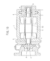
- the disclosed supercharger comprises a compressor 2 housed in a casing 1 and a bearing device 4 which supports a rotational shaft 3 of the compressor 2.
- the casing 1 also houses therein an electric motor 5 for rotating the rotational shaft 3 at a high speed, a pair of front and rear radial foil bearings 6 which support the rotational shaft 3 in radial directions, a pair of front and rear axial foil bearings 7 which support the rotational shaft 3 in axial directions (longitudinal directions), and an auxiliary bearing means 8 which subsidiarily supports the rotational shaft 3 in both radial and axial directions.
- the bearing device 4 includes the radial foil bearings 6, the axial foil bearings 7, and the auxiliary bearing means 8.
- the rotational shaft 3 is of a stepped shape including a central large-diameter portion on which a rotor 5a of the electric motor 5 is mounted and a small-diameter portion at an end thereof on which an impeller 9 is mounted.
- the supercharger requires that the rotational shaft 3 be rotated at a high speed. However, when the rotational shaft 3 is rotated at a high speed, the iron loss of the rotor 5a increases, thus making it difficult to operate the supercharger at temperatures below the heat-resistant temperature of the magnets of the electric motor 5.
- a motor-driven centrifugal compressor for compressing air and supplying the compressed air by driving of an electric motor.
- the motor-driven centrifugal compressor includes a gas bearing including an elastic metal member for restraining a rotatable member in a resting state and forming an air layer between the elastic metal member and the rotatable member in a rotating state, and a stationary holding member disposed in confronting relation to the rotatable member, the elastic metal member being fixed to the stationary holding member.
- the stationary holding member has a coolant channel defined therein, and the rotatable member, the air layer, the elastic metal member, and the coolant channel are arranged in the order named along a normal direction which is normal to a tangential direction which is tangential to the air layer or along a normal direction which is normal to a surface of the rotatable member which faces the air layer.
- an air flow speed difference in the air layer formed between the rotatable member and the stationary holding member i.e., between a radially inner air layer and a radially outer air layer.
- the air flow speed difference enables a good heat transfer between the rotatable member and the stationary holding member. Specifically, heat generated by the rotatable member is transferred smoothly from the rotatable member through the air layer, the elastic metal member, and the coolant channel which are arranged successively along the normal direction. Therefore, the heat generated by the rotatable member upon rotation is efficiently removed by a simple and compact structure, thereby allowing the rotatable member to rotate at a high speed advantageously.
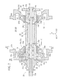
- a motor-driven centrifugal compressor 10 includes a casing 12 in which a rotatable shaft unit 14 is rotatably mounted.
- the rotatable shaft unit 14 comprises a rotor 20 having an annular permanent magnet 16 and a hollow cylindrical protective sleeve 18 disposed around the permanent magnet 16 and housing therein the permanent magnet 16, which may be shrink-fit in the protective sleeve 18, for example, a pair of bearing shafts 22, 24 mounted on respective axial opposite ends as rotatable members, in particular, rotatable shafts, and an impeller 26 mounted on the axial end of the bearing shaft 22 that is remote from the rotor 20.
- the impeller 26 serves as part of a centrifugal compression unit 28 and has an end face held against a large-diameter end 30a of a tension shaft 30.
- the tension shaft 30 which extends axially through the impeller 26 supports thereon the bearing shaft 22, the rotor 20, and the bearing shaft 24 which are arranged successively in the order named from the impeller 26.
- the bearing shaft 22, the rotor 20, and the bearing shaft 24 are integrally held together on the tension shaft 30 by a fastening member 32 that is threaded over the end of the tension shaft 30 which is remote from the large-diameter end 30a thereof.
- the fastening member 32 supports thereon a canceler mechanism 34 for reducing thrust force that is generated along the direction indicated by the arrow A1 when the rotatable shaft unit 14 rotates about its own axis.
- the canceler mechanism 34 includes a canceler disk 38 which is slidable in a pressurization chamber 36 along the directions indicated by the arrow A. When the impeller 26 rotates about its own axis, air is generated, and the generated air flows into the pressurization chamber 36 through a passageway 40.
- the casing 12 houses therein an annular stator 42 fixedly disposed around the rotor 20.
- the stator 42 and the rotor 20 jointly make up a motor 46.
- the motor 46 includes conical (more specifically, bugle-shaped) linkage members 46a, 46b disposed on its axial ends around the rotatable shaft (i.e., the rotor 20, the bearing shafts 22, 24, etc.).
- a plurality of coolant water channels (coolant channels) 48 extend around the stator 42.
- the protective sleeve 18 has hollow cylindrical protrusions 18a, 18b disposed on its opposite ends on which the bearing shafts 22, 24 are mounted.
- the protrusions 18a, 18b project axially outwardly beyond respective end faces 16a, 16b of the permanent magnet 16.
- the bearing shaft 22 includes a hollow cylindrical member 22a which is open at an axial end thereof and a bottom 22b which is disposed at an opposite axial end thereof and projects radially inwardly to the tension shaft 30.
- the bearing shaft 24 includes a hollow cylindrical member 24a which is open at an axial end thereof and a bottom 24b which is disposed at an opposite axial end thereof and projects radially inwardly to the tension shaft 30.
- the bottom 22b of the bearing shaft 22 is held in contact with the hollow cylindrical protrusion 18a of the protective sleeve 18, and the bottom 24b of the bearing shaft 24 is held in contact with the hollow cylindrical protrusion 18b of the protective sleeve 18.
- the bottoms 22b, 24b and the end faces 16a, 16b of the permanent magnet 16 are spaced from each other by respective distances S1, S2.
- a foil gas bearing 50 which holds the bearing shafts 22, 24 is disposed in confronting relation to outer circumferential surfaces of the bearing shafts 22, 24.
- the foil gas bearing 50 comprises journal air bearings (journal gas bearings) 52a, 52b which hold the bearing shafts 22, 24 in their radial positions and a thrust air bearing (thrust gas bearing) 54 which holds the bearing shaft 22 in its axial position.
- the bearing shafts 22, 24, which serve as part of the journal air bearings 52a, 52b, are made of the same nickel-based superalloy as the protective sleeve 18, for example.
- the journal air bearings 52a, 52b comprise respective ring members 56A, 56B disposed around the outer circumferential surfaces of the bearing shafts 22, 24 with prescribed clearances therebetween.
- the bearing shafts 22, 24 are rotatably supported by the ring members 56A, 56B, which are nonrotatably fixed to first and second stationary holding members 57A, 57B, respectively.
- the ring members 56A, 56B serve as part of the journal air bearings 52a, 52b.
- a corrugated-sheet-like bump foil 58 and a flat-sheet-like top foil 60 are arranged successively in the order named on an inner circumferential surface 56a of the ring member 56A.
- the bump foil 58 comprises a single elastic metal member or a plurality of elastic metal members made of iron, aluminum, Inconel, or the like, and has an end 58a fixed by welding or the like to the inner circumferential surface 56a of the ring member 56A and an opposite end as a free end.
- the top foil 60 comprises an elastic metal member made of iron, aluminum, Inconel, or the like, and is in the form of a flat sheet curved into an annular shape.
- the top foil 60 has an end 60a fixed by welding or the like to the inner circumferential surface 56a of the ring member 56A and an opposite end as a free end.
- the bearing shaft 22 When the bearing shaft 22 is at rest (in a resting state), it is restrained by the top foil 60.
- an air layer 61 is formed between the bearing shaft 22 and the top foil 60.
- the ring member 56B is of the same structure as the ring member 56A.
- the bearing shaft 22 has a large-diameter flange 62 projecting radially outwardly from the outer circumferential surface thereof.
- the large-diameter flange 62 is sandwiched between ring members 64a, 64b that are disposed on respective axially opposite sides thereof.
- the large-diameter flange 62 and the ring members 64a, 64b jointly make up the thrust air bearing 54.
- each of the ring members 64a, 64b has corrugated-sheet-like bump foils 66 and flat-sheet-like top foils 68 disposed on a surface thereof that faces the large-diameter flange 62.
- Each of the bump foils 66 and the top foils 68 comprises an elastic metal member made of iron, aluminum, Inconel, or the like.
- the bump foils 66 and the top foils 68 are superposed and arrayed in an annular pattern along an inner circumferential edge of each of the ring members 64a, 64b.
- each of the bump foils 66 has an end 66a fixed to one of the ring members 64a, 64b by welding or the like and an opposite end 66b as a free end.
- Each of the top foils 68 has an end 68a fixed to one of the ring members 64a, 64b by welding or the like and an opposite end 68b as a free end.
- the impeller 26 has an axial end 26a which is remote from the large-diameter end 30a of the tension shaft 30 and coaxially fitted in the hollow cylindrical member 22a of the bearing shaft 22 by a spigot-and-socket joint.
- the bottoms 22b, 24b of the bearing shafts 22, 24 are coaxially fitted respectively in the hollow cylindrical protrusions 18a, 18b of the protective sleeve 18 by a spigot-and-socket joint.
- the casing 12 has a coolant channel 70 defined between the protective sleeve 18 and the stator 42 of the motor 46.
- the inlet of the coolant channel 70 and the passageway 40 of the canceler mechanism 34 are connected to a compressor outlet 72 of the centrifugal compression unit 28.
- the impeller 26 rotates about its own axis, it compresses air and delivers the compressed air from the compressor outlet 72 into the inlet of the coolant channel 70 and the passageway 40 of the canceler mechanism 34.
- the first stationary holding member 57A has a coolant water channel (coolant channel) 74 defined therein
- the second stationary holding member 57B has a coolant water channel (coolant channel) 76 defined therein.
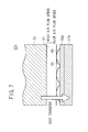
- the bearing shaft 22, the air layer 61, the top foil 60, the bump foil 58, and the coolant water channel 74 are arranged in the order named along a normal direction which is normal to a tangential direction which is tangential to the air layer 61.
- the bearing shaft 24, the air layer 61, the top foil 60, the bump foil 58, and the coolant water channel 76 are arranged in the order named along the normal direction.
- the large-diameter flange 62, the air layer 69, the top foil 68, the bump foil 66 on the ring member 64a, and the coolant water channel 74 are arranged in the order named along a normal direction which is normal to a surface of the large-diameter flange 62 which faces the air layer 69.
- the coolant water channels 74, 76 have their axial opening width which is progressively greater toward the central axis of the first and second stationary holding members 57A, 57B.
- the coolant water channel 74 is defined, in an axial cross section, by a first inner wall surface 74a extending in a thrust direction, i.e., the direction indicated by the arrow B, which is perpendicular to an axial direction, i.e., the direction indicated by the arrow A, of the rotatable shaft unit 14, the first inner wall surface 74a facing the thrust air bearing 54, and a second inner wall surface 74b extending in the axial direction and which faces the journal air bearing 52a.
- the casing 12 has a coolant water inlet 78 on the canceler mechanism 34 side and a coolant water outlet 80 on the impeller 26 side.
- the coolant water inlet 78 is connected to the coolant water channel 76 through a passage 82.
- the coolant water channel 76 is of a ring shape extending around the outer circumferential surface of the journal air bearing 52b.
- the coolant water channel 76 has a lower end connected to an end of a passage 84 whose other end is connected to the coolant water channels 48 which extend around the outer circumferential surface of the stator 42.
- the coolant water channels 48 which extend around the motor 46, allow a coolant water to flow therein in the direction indicated by the arrow A.
- the coolant water channels 48 have an outlet on the impeller 26 side which is connected through a passage 86 to the coolant water channel 74.
- the coolant water channel 74 extends around the journal air bearing 52a and the thrust air bearing 54, and is connected through a passage 88 to the coolant water outlet 80.
- journal air bearings 52a, 52b extend respectively into the linkage members 46a, 46b of the motor 46 by respective distances L1, L2.
- the first and second stationary holding members 57A, 57B have respective inner circumferential surfaces 57a, 57b surrounding the entire outer circumferential surfaces of the journal air bearings 52a, 52b.
- the first and second stationary holding members 57A, 57B have respective air vent holes 90a, 90b defined therein for preventing air from being trapped in the thrust air bearing 54 and the journal air bearings 52a, 52b.
- the air that is drawn by the impeller 26 is compressed and fed by the centrifugal compression unit 28 to the oxygen-containing gas supply system of a fuel cell (not shown), for example.
- the fuel cell is supplied with a fuel gas, i.e., a hydrogen gas, from a fuel gas supply system (not shown). Therefore, the fuel cell generates electric energy based on a reaction between the air that is supplied to the cathode of the fuel cell and the hydrogen that is supplied to the anode of the fuel cell.
- Part of the air compressed by the centrifugal compression unit 28 is supplied from the compressor outlet 72 through the passageway 40 of the canceler mechanism 34 to the pressurization chamber 36.
- the air flows into the pressurization chamber 36, it applies a pressing force to the canceler disk 38 in the pressurization chamber 36 in a direction away from the impeller 26, i.e., in the direction indicated by the arrow A2. Therefore, the thrust force applied in the direction indicated by the arrow A1 is reduced by the canceler mechanism 34 upon rotation of the impeller 26.
- the bearing shafts 22, 24 are restrained by the inner circumferential surfaces of the top foils 60 of the journal air bearings 52a, 52b.
- the bump foils 58 are elastically deformed toward the inner circumferential surfaces 56a, 56b of the ring members 56A, 56B by the viscosity of the air which acts as a working gas. Therefore, the air layers 61 are formed between the top foils 60 and the outer circumferential surfaces of the bearing shafts 22, 24.
- the air layer 61 is formed between the outer circumferential surface of the bearing shaft 22 and the top foil 60.
- the air flow speed is higher in the vicinity of the bearing shaft 22 that is rotating at a high speed, while the air flow speed is lower in the vicinity of the top foil 60. Therefore, a good heat transfer is achieved from the bearing shafts 22, 24 through the air layer 61 toward the top foil 60.
- the bearing shaft 22, the air layer 61, the top foil 60, the bump foil 58, and the coolant water channel 74 are arranged in the order named along the normal direction that is normal to the bearing shaft 22. Owing thereto, the heat of the bearing shaft 22 which is rotating at a high speed is smoothly transferred to the air layer 61, the top foil 60, the bump foil 58, and the coolant water channel 74, advantageously.
- the large-diameter flange 62 of the thrust air bearing 54 rotates at a high speed in unison with the bearing shaft 22, with the air layer 69 being formed between the large-diameter flange 62 and each of the top foils 68.
- the large-diameter flange 62, the air layer 69, the top foil 68, the bump foil 66 on the ring member 64a, and the coolant water channel 74 are arranged in the order named along the normal direction which is normal to the surface of the large-diameter flange 62 which faces the air layer 69. Therefore, the heat of the large-diameter flange 62 is smoothly and reliably transferred to the air layer 69, the top foil 68, the bump foil 66, and the coolant water channel 74, and hence is efficiently removed.
- the motor 46 includes the conical linkage members 46a, 46b disposed on its axial ends, and at least portions of the journal air bearings 52a, 52b extend respectively into the linkage members 46a, 46b.
- the inner circumferential surfaces 57a, 57b of the first and second stationary holding members 57A, 57B surround the entire circumferential surfaces of the journal air bearings 52a, 52b. Therefore, the journal air bearings 52a, 52b can be arranged as close to the stator 42 as possible, thereby making it possible to reduce the entire axial length of the rotatable shaft unit 14.
- the rotatable shaft unit 14 can thus be reduced in size and can have its resonant frequency shifted into a higher frequency range, so that the rotatable shaft unit 14 is well prevented from resonating during rotation thereof.
- the coolant water channels 74, 76 defined in the first and second stationary holding members 57A, 57B have their axial opening width which is progressively greater toward the central axis of the first and second stationary holding members 57A, 57B. Accordingly, the coolant water channels 74, 76 have a relatively large surface area for effectively cooling the bearing shafts 22, 24 uniformly along their axes.
- the coolant water channel 74 is defined by the first inner wall surface 74a extending in the thrust direction, i.e., in the direction indicated by the arrow B, of the rotatable shaft unit 14 in confronting relation to the thrust air bearing 54, and the second inner wall surface 74b extending in the axial direction, i.e., in the direction indicated by the arrow A, in confronting relation to the journal air bearing 52a. Therefore, the thrust air bearing 54 and the journal air bearing 52a can be cooled through the single coolant water channel 74, thereby achieving a simple structure.
- the coolant water is supplied from the coolant water inlet 78 through the passage 82 to the coolant water channel 76 on the journal air bearing 52b side. Then, the coolant water flows through the passage 84 into the coolant water channels 48 around the stator 42. Thereafter, the coolant water flows through the coolant water channels 48 and then through the passage 86 into the coolant water channel 74 on the journal air bearing 52a side, from which the coolant water is discharged through the passage 88 into the coolant water outlet 80. The coolant water thus cools the journal air bearing 52b, the stator 42, and the journal air bearing 52a successively in the order named. As the coolant water first cools the journal air bearing 52b which has less heat radiation routes, the coolant water is able to uniformize the temperatures of the journal air bearings 52a, 52b.
- the foil gas bearing 50 is used as a gas bearing in the present embodiment.
- the present invention is also applicable to other gas bearings such as air bearings employing a tilting pad of metal.
- the coolant water inlet 78 is disposed on the canceler mechanism 34 side, and the coolant water outlet 80 is disposed on the impeller 26 side.
- the coolant water outlet 80 may be disposed on the canceler mechanism 34 side, and the coolant water inlet 78 may be disposed on the impeller 26 side.
- the coolant water flows from the coolant water channel 74 on the journal air bearing 52a side through the coolant water channel 48 into the coolant water channel 76 on the journal air bearing 52b side.
- a motor-driven centrifugal compressor (10) includes a journal air bearing (52a) having a bump foil (58) and a top foil (60) for restraining a bearing shaft (22) in a resting state and forming an air layer (61) between the top foil (60) and the bearing shaft (22) in a rotating state.
- the top foil (60) and the bump foil (58) are fixed to an inner circumferential surface (56a) of a ring member (56A), which is fixed to an inner circumferential surface (57a) of a first stationary holding member (57A) of the ring member (56A).
- the first stationary holding member (57A) has a coolant water channel (74) defined therein.
- the bearing shaft (22), the air layer (61), the top foil (60), the bump foil (58), and the coolant water channel (74) are arranged in the order named along a normal direction.
Landscapes
- Engineering & Computer Science (AREA)
- General Engineering & Computer Science (AREA)
- Mechanical Engineering (AREA)
- Physics & Mathematics (AREA)
- Fluid Mechanics (AREA)
- Chemical & Material Sciences (AREA)
- Combustion & Propulsion (AREA)
- Thermal Sciences (AREA)
- Structures Of Non-Positive Displacement Pumps (AREA)
- Support Of The Bearing (AREA)
Applications Claiming Priority (1)
| Application Number | Priority Date | Filing Date | Title |
|---|---|---|---|
| JP2010083873A JP4932921B2 (ja) | 2010-03-31 | 2010-03-31 | 電動遠心圧縮機 |
Publications (2)
| Publication Number | Publication Date |
|---|---|
| EP2375082A2 true EP2375082A2 (fr) | 2011-10-12 |
| EP2375082A3 EP2375082A3 (fr) | 2011-11-23 |
Family
ID=44310857
Family Applications (1)
| Application Number | Title | Priority Date | Filing Date |
|---|---|---|---|
| EP11159709A Withdrawn EP2375082A3 (fr) | 2010-03-31 | 2011-03-25 | Compresseur centrifuge commandé par moteur |
Country Status (3)
| Country | Link |
|---|---|
| US (1) | US20110243762A1 (fr) |
| EP (1) | EP2375082A3 (fr) |
| JP (1) | JP4932921B2 (fr) |
Cited By (6)
| Publication number | Priority date | Publication date | Assignee | Title |
|---|---|---|---|---|
| DE102014018070A1 (de) | 2014-12-09 | 2015-07-02 | Daimler Ag | Lagereinrichtung zum Lagern eines Rotors einer Strömungsmaschine |
| CN105492786A (zh) * | 2013-09-06 | 2016-04-13 | Ntn株式会社 | 箔片轴承单元 |
| DE102015211042A1 (de) * | 2015-06-16 | 2016-12-22 | Robert Bosch Gmbh | Vorrichtung zum Komprimieren eines Fluids und Herstellungsverfahren für eine Vorrichtung zum Komprimieren eines Fluids |
| EP3096028A4 (fr) * | 2013-12-12 | 2017-11-08 | NTN Corporation | Palier à feuilles, et unité de palier à feuilles et turbomachine comportant chacun ce dernier |
| FR3063780A1 (fr) * | 2017-03-10 | 2018-09-14 | Valeo Systemes De Controle Moteur | Compresseur electrique avec circuit de refroidissement |
| WO2024103959A1 (fr) * | 2022-11-16 | 2024-05-23 | 珠海格力电器股份有限公司 | Compresseur et climatiseur |
Families Citing this family (49)
| Publication number | Priority date | Publication date | Assignee | Title |
|---|---|---|---|---|
| WO2013028521A1 (fr) * | 2011-08-24 | 2013-02-28 | Borgwarner Inc. | Dispositif d'alimentation en air pour pile à combustible |
| KR102077148B1 (ko) * | 2011-08-24 | 2020-02-14 | 보르그워너 인코퍼레이티드 | 베어링 장치 |
| US20130129488A1 (en) * | 2011-11-18 | 2013-05-23 | Giridhari L. Agrawal | Foil bearing supported motor-driven blower |
| US10598222B2 (en) | 2012-01-03 | 2020-03-24 | New Way Machine Components, Inc. | Air bearing for use as seal |
| EP2800917B1 (fr) | 2012-01-03 | 2020-07-22 | New Way Machine Components, Inc. | Palier à air servant de joint d'étanchéité |
| US9109622B2 (en) * | 2012-11-19 | 2015-08-18 | Honeywell International Inc. | Rotor support structures including anisotropic foil bearings or anisotropic bearing housings and methods for controlling non-synchronous vibrations of rotating machinery using the same |
| US9157473B2 (en) * | 2013-01-16 | 2015-10-13 | Korea Institute Of Machinery & Materials | Thrust bearing and combo bearing |
| KR101443036B1 (ko) * | 2013-04-30 | 2014-09-22 | 한국기계연구원 | 에어포일 쓰러스트 베어링 및 메탈메쉬포일 래디얼 베어링을 포함하는 분할형 콤보 베어링 |
| JP6257965B2 (ja) * | 2013-09-06 | 2018-01-10 | Ntn株式会社 | フォイル軸受ユニット |
| JP6167037B2 (ja) * | 2013-12-24 | 2017-07-19 | 三鷹光器株式会社 | 断熱軸受構造 |
| US9709068B2 (en) | 2014-02-19 | 2017-07-18 | Honeywell International Inc. | Sealing arrangement for fuel cell compressor |
| US20150308456A1 (en) * | 2014-02-19 | 2015-10-29 | Honeywell International Inc. | Electric motor-driven compressor having bi-directional liquid coolant passage |
| TWM483123U (zh) * | 2014-03-11 | 2014-08-01 | Trusval Technology Co Ltd | 氣體溶解於液體的生成裝置及流體噴頭 |
| JP2017089384A (ja) * | 2014-03-19 | 2017-05-25 | 株式会社豊田自動織機 | 電動ターボ式圧縮機 |
| US9537363B2 (en) | 2014-04-30 | 2017-01-03 | Honeywell International Inc. | Electric motor-driven compressor having an electrical terminal block assembly |
| CA2962898C (fr) | 2014-09-29 | 2019-06-25 | New Way Machine Components, Inc. | Palier de butee sous la forme d'un joint d'etancheite |
| KR102159291B1 (ko) * | 2015-03-23 | 2020-09-23 | 한온시스템 주식회사 | 차량용 공기 블로어 |
| JP2016192877A (ja) * | 2015-03-31 | 2016-11-10 | 株式会社豊田自動織機 | 回転電機および圧縮機 |
| DE102015005034A1 (de) * | 2015-04-21 | 2016-10-27 | Daimler Ag | Abgasturbolader für eine Verbrennungskraftmaschine, insbesondere eines Kraftwagens |
| FR3045111B1 (fr) * | 2015-12-14 | 2017-12-01 | Labinal Power Systems | Compresseur centrifuge electrique de turbomachine ou d'aeronef |
| EP3208468A1 (fr) * | 2016-02-22 | 2017-08-23 | Siemens Turbomachinery Equipment GmbH | Compresseur radial |
| KR102447823B1 (ko) * | 2016-03-22 | 2022-09-27 | 한온시스템 주식회사 | 차량용 공기 압축기 |
| FR3055678B1 (fr) * | 2016-09-02 | 2020-09-18 | Danfoss Silicon Power Gmbh | Agencement de palier axial pour un arbre d'entrainement d'un compresseur centrifuge |
| US10371156B2 (en) * | 2016-09-02 | 2019-08-06 | Hamilton Sundstrand Corporation | Ventilation fan having air bearing system |
| US10876539B2 (en) | 2016-09-07 | 2020-12-29 | Hamilton Sunstrand Corporation | Ventilation fan having a hybrid bearing system |
| JP6756382B2 (ja) * | 2017-01-25 | 2020-09-16 | 株式会社Ihi | 電動コンプレッサ |
| FR3063776A1 (fr) | 2017-03-08 | 2018-09-14 | BD Kompressor GmbH | Agencement de palier pour un arbre d'entrainement d'une turbomachine, et une turbomachine comportant un tel agencement de palier |
| JP6944853B2 (ja) | 2017-11-15 | 2021-10-06 | 株式会社マーレ フィルターシステムズ | 電動コンプレッサ |
| EP3557079A1 (fr) * | 2018-04-20 | 2019-10-23 | Belenos Clean Power Holding AG | Système de chauffage, ventilation et climatisation comprenant un compresseur de fluide |
| US10775298B1 (en) * | 2018-05-14 | 2020-09-15 | J.A. Woollam Co., Inc. | Ellipsometer or polarimeter system having at least one rotating element which is driven by a motor comprising air bearing |
| US10774873B2 (en) | 2018-06-11 | 2020-09-15 | Trane International Inc. | Porous gas bearing |
| US10753392B2 (en) | 2018-06-11 | 2020-08-25 | Trane International Inc. | Porous gas bearing |
| CN111365256B (zh) * | 2018-12-25 | 2025-07-25 | 珠海格力电器股份有限公司 | 离心压缩机及空调设备 |
| JP2020105993A (ja) | 2018-12-28 | 2020-07-09 | 株式会社マーレ フィルターシステムズ | 電動コンプレッサ |
| WO2020163605A1 (fr) * | 2019-02-07 | 2020-08-13 | Emerson Climate Technologies, Inc. | Ensemble palier à feuilles |
| US11306726B2 (en) * | 2019-03-11 | 2022-04-19 | Emerson Climate Technologies, Inc. | Foil bearing assembly and compressor including same |
| KR102171452B1 (ko) | 2019-06-21 | 2020-10-29 | 엘지전자 주식회사 | 모터 어셈블리 및 그 제조 방법 |
| KR102196317B1 (ko) * | 2019-07-16 | 2020-12-29 | 엘지전자 주식회사 | 팬 모터 및 베어링 |
| JP7523087B2 (ja) * | 2020-02-20 | 2024-07-26 | パナソニックIpマネジメント株式会社 | 軸受構造 |
| CN115803531B (zh) * | 2020-07-15 | 2025-09-16 | 三菱重工发动机和增压器株式会社 | 多级电动离心压缩机 |
| CN112160915B (zh) | 2020-09-22 | 2025-07-11 | 珠海格力电器股份有限公司 | 压缩机 |
| US20220220976A1 (en) * | 2021-01-12 | 2022-07-14 | Emerson Climate Technologies, Inc. | Cooling system for centrifugal compressor and refrigeration system including same |
| KR102508011B1 (ko) * | 2021-02-24 | 2023-03-09 | ㈜티앤이코리아 | 베어링 냉각 수로를 포함하는 터보 압축기 |
| DE102021124547A1 (de) | 2021-09-22 | 2023-03-23 | Borgwarner Inc. | Aufladevorrichtung |
| JP7669909B2 (ja) * | 2021-11-19 | 2025-04-30 | 株式会社豊田自動織機 | 遠心圧縮機 |
| JP7401801B2 (ja) * | 2022-03-30 | 2023-12-20 | ダイキン工業株式会社 | 圧縮機、および冷凍装置 |
| JP7775868B2 (ja) * | 2023-06-15 | 2025-11-26 | 株式会社豊田自動織機 | 圧縮機の取付構造および圧縮機 |
| US12497995B2 (en) * | 2024-01-17 | 2025-12-16 | Hamilton Sundstrand Corporation | Microscopic surface texturing for shouldered shaft and bearing pads |
| DE102024102696A1 (de) * | 2024-01-31 | 2025-07-31 | Ebm-Papst Mulfingen Gmbh & Co. Kg | Aerodynamisches Lager zur axialen und radialen Lagerung einer Welle sowie Turbokompressor mit einem solchen Lager |
Citations (1)
| Publication number | Priority date | Publication date | Assignee | Title |
|---|---|---|---|---|
| JP2007092646A (ja) | 2005-09-29 | 2007-04-12 | Jtekt Corp | 燃料電池用過給機 |
Family Cites Families (8)
| Publication number | Priority date | Publication date | Assignee | Title |
|---|---|---|---|---|
| US3933416A (en) * | 1945-05-01 | 1976-01-20 | Donelian Khatchik O | Hermatically sealed motor blower unit with stator inside hollow armature |
| CH381026A (de) * | 1961-02-14 | 1964-08-15 | Bbc Brown Boveri & Cie | Wärmeschutz eines Lagers |
| IL109967A (en) * | 1993-06-15 | 1997-07-13 | Multistack Int Ltd | Compressor |
| US5957667A (en) * | 1997-05-23 | 1999-09-28 | Ballard Generation Systems Inc. | Oilless compressor with a pressurizable crankcase and motor containment vessel |
| US7302804B2 (en) * | 2003-06-24 | 2007-12-04 | Honeywell International, Inc. | Cabin air compressor cooling system |
| JP2008193756A (ja) * | 2007-01-31 | 2008-08-21 | Jtekt Corp | 回転機器 |
| US7704056B2 (en) * | 2007-02-21 | 2010-04-27 | Honeywell International Inc. | Two-stage vapor cycle compressor |
| US20080199326A1 (en) * | 2007-02-21 | 2008-08-21 | Honeywell International Inc. | Two-stage vapor cycle compressor |
-
2010
- 2010-03-31 JP JP2010083873A patent/JP4932921B2/ja not_active Expired - Fee Related
-
2011
- 2011-03-25 EP EP11159709A patent/EP2375082A3/fr not_active Withdrawn
- 2011-03-30 US US13/076,084 patent/US20110243762A1/en not_active Abandoned
Patent Citations (1)
| Publication number | Priority date | Publication date | Assignee | Title |
|---|---|---|---|---|
| JP2007092646A (ja) | 2005-09-29 | 2007-04-12 | Jtekt Corp | 燃料電池用過給機 |
Cited By (6)
| Publication number | Priority date | Publication date | Assignee | Title |
|---|---|---|---|---|
| CN105492786A (zh) * | 2013-09-06 | 2016-04-13 | Ntn株式会社 | 箔片轴承单元 |
| EP3096028A4 (fr) * | 2013-12-12 | 2017-11-08 | NTN Corporation | Palier à feuilles, et unité de palier à feuilles et turbomachine comportant chacun ce dernier |
| DE102014018070A1 (de) | 2014-12-09 | 2015-07-02 | Daimler Ag | Lagereinrichtung zum Lagern eines Rotors einer Strömungsmaschine |
| DE102015211042A1 (de) * | 2015-06-16 | 2016-12-22 | Robert Bosch Gmbh | Vorrichtung zum Komprimieren eines Fluids und Herstellungsverfahren für eine Vorrichtung zum Komprimieren eines Fluids |
| FR3063780A1 (fr) * | 2017-03-10 | 2018-09-14 | Valeo Systemes De Controle Moteur | Compresseur electrique avec circuit de refroidissement |
| WO2024103959A1 (fr) * | 2022-11-16 | 2024-05-23 | 珠海格力电器股份有限公司 | Compresseur et climatiseur |
Also Published As
| Publication number | Publication date |
|---|---|
| JP4932921B2 (ja) | 2012-05-16 |
| EP2375082A3 (fr) | 2011-11-23 |
| JP2011214523A (ja) | 2011-10-27 |
| US20110243762A1 (en) | 2011-10-06 |
Similar Documents
| Publication | Publication Date | Title |
|---|---|---|
| US20110243762A1 (en) | Motor-driven centrifugal compressor | |
| EP2375089B1 (fr) | Palier à gaz de feuille dynamique | |
| US8821136B2 (en) | Supercharger | |
| EP2924294B1 (fr) | Compresseur entraîné par un moteur électrique comportant un écran thermique formant une paroi d'un diffuseur | |
| US8215928B2 (en) | Foil gas bearing supported high temperature centrifugal blower and method for cooling thereof | |
| EP2940835B1 (fr) | Compresseur entraîné par un moteur électrique ayant un passage de liquide de refroidissement bidirectionnel | |
| JP2011202588A (ja) | 遠心型圧縮機 | |
| WO2005046021A2 (fr) | Système rotor et palier pour turbomachine | |
| JP5174074B2 (ja) | 電動遠心圧縮機 | |
| CN105144551B (zh) | 感应电机 | |
| JP2008193756A (ja) | 回転機器 | |
| JP2011202589A (ja) | 遠心型圧縮機 | |
| JP5497489B2 (ja) | 遠心型圧縮機 | |
| US20130115074A1 (en) | Turbo molecular pump device | |
| EP2775148A1 (fr) | Élément fixe et pompe à vide | |
| JP5094897B2 (ja) | 電動遠心圧縮機 | |
| JP5174069B2 (ja) | 遠心型圧縮機 | |
| JP2003230253A (ja) | 回転電機 | |
| JP4426259B2 (ja) | ガスタービン設備及びガスタービン発電設備 | |
| WO2019151186A1 (fr) | Ensemble moteur électrique | |
| JP5208055B2 (ja) | ロータ構造 | |
| JP2015143474A (ja) | ターボ機械 | |
| JP2011166189A (ja) | 平面型ディスプレイテレビ用放熱機構 | |
| EP4344029A1 (fr) | Agencement de refroidissement pour rotor de machine électrique | |
| EP4722511A1 (fr) | Compresseur de suralimentation électrique |
Legal Events
| Date | Code | Title | Description |
|---|---|---|---|
| PUAI | Public reference made under article 153(3) epc to a published international application that has entered the european phase |
Free format text: ORIGINAL CODE: 0009012 |
|
| 17P | Request for examination filed |
Effective date: 20110325 |
|
| AK | Designated contracting states |
Kind code of ref document: A2 Designated state(s): AL AT BE BG CH CY CZ DE DK EE ES FI FR GB GR HR HU IE IS IT LI LT LU LV MC MK MT NL NO PL PT RO RS SE SI SK SM TR |
|
| AX | Request for extension of the european patent |
Extension state: BA ME |
|
| PUAL | Search report despatched |
Free format text: ORIGINAL CODE: 0009013 |
|
| AK | Designated contracting states |
Kind code of ref document: A3 Designated state(s): AL AT BE BG CH CY CZ DE DK EE ES FI FR GB GR HR HU IE IS IT LI LT LU LV MC MK MT NL NO PL PT RO RS SE SI SK SM TR |
|
| AX | Request for extension of the european patent |
Extension state: BA ME |
|
| RIC1 | Information provided on ipc code assigned before grant |
Ipc: F16C 37/00 20060101ALI20111017BHEP Ipc: F16C 17/12 20060101ALI20111017BHEP Ipc: F04D 29/58 20060101ALI20111017BHEP Ipc: F04D 29/057 20060101ALI20111017BHEP Ipc: F04D 25/06 20060101AFI20111017BHEP |
|
| 17Q | First examination report despatched |
Effective date: 20111102 |
|
| STAA | Information on the status of an ep patent application or granted ep patent |
Free format text: STATUS: THE APPLICATION IS DEEMED TO BE WITHDRAWN |
|
| 18D | Application deemed to be withdrawn |
Effective date: 20151001 |