EP2375101A2 - Doppelkupplungsgetriebe eines Kraftfahrzeugs mit Gangschaltungsvorrichtung, die eine Drehtrommel umfasst, und Hybridantriebssystem eines Kraftfahrzeugs, das ein solches Getriebe beinhaltet - Google Patents
Doppelkupplungsgetriebe eines Kraftfahrzeugs mit Gangschaltungsvorrichtung, die eine Drehtrommel umfasst, und Hybridantriebssystem eines Kraftfahrzeugs, das ein solches Getriebe beinhaltet Download PDFInfo
- Publication number
- EP2375101A2 EP2375101A2 EP11170473A EP11170473A EP2375101A2 EP 2375101 A2 EP2375101 A2 EP 2375101A2 EP 11170473 A EP11170473 A EP 11170473A EP 11170473 A EP11170473 A EP 11170473A EP 2375101 A2 EP2375101 A2 EP 2375101A2
- Authority
- EP
- European Patent Office
- Prior art keywords
- gear
- engagement
- iii
- gearwheel
- gearbox
- Prior art date
- Legal status (The legal status is an assumption and is not a legal conclusion. Google has not performed a legal analysis and makes no representation as to the accuracy of the status listed.)
- Granted
Links
Images


Classifications
-
- F—MECHANICAL ENGINEERING; LIGHTING; HEATING; WEAPONS; BLASTING
- F16—ENGINEERING ELEMENTS AND UNITS; GENERAL MEASURES FOR PRODUCING AND MAINTAINING EFFECTIVE FUNCTIONING OF MACHINES OR INSTALLATIONS; THERMAL INSULATION IN GENERAL
- F16H—GEARING
- F16H37/00—Combinations of mechanical gearings, not provided for in groups F16H1/00 - F16H35/00
- F16H37/02—Combinations of mechanical gearings, not provided for in groups F16H1/00 - F16H35/00 comprising essentially only toothed or friction gearings
- F16H37/06—Combinations of mechanical gearings, not provided for in groups F16H1/00 - F16H35/00 comprising essentially only toothed or friction gearings with a plurality of driving or driven shafts; with arrangements for dividing torque between two or more intermediate shafts
- F16H37/065—Combinations of mechanical gearings, not provided for in groups F16H1/00 - F16H35/00 comprising essentially only toothed or friction gearings with a plurality of driving or driven shafts; with arrangements for dividing torque between two or more intermediate shafts with a plurality of driving or driven shafts
-
- B—PERFORMING OPERATIONS; TRANSPORTING
- B60—VEHICLES IN GENERAL
- B60K—ARRANGEMENT OR MOUNTING OF PROPULSION UNITS OR OF TRANSMISSIONS IN VEHICLES; ARRANGEMENT OR MOUNTING OF PLURAL DIVERSE PRIME-MOVERS IN VEHICLES; AUXILIARY DRIVES FOR VEHICLES; INSTRUMENTATION OR DASHBOARDS FOR VEHICLES; ARRANGEMENTS IN CONNECTION WITH COOLING, AIR INTAKE, GAS EXHAUST OR FUEL SUPPLY OF PROPULSION UNITS IN VEHICLES
- B60K6/00—Arrangement or mounting of plural diverse prime-movers for mutual or common propulsion, e.g. hybrid propulsion systems comprising electric motors and internal combustion engines
- B60K6/20—Arrangement or mounting of plural diverse prime-movers for mutual or common propulsion, e.g. hybrid propulsion systems comprising electric motors and internal combustion engines the prime-movers consisting of electric motors and internal combustion engines, e.g. HEVs
- B60K6/22—Arrangement or mounting of plural diverse prime-movers for mutual or common propulsion, e.g. hybrid propulsion systems comprising electric motors and internal combustion engines the prime-movers consisting of electric motors and internal combustion engines, e.g. HEVs characterised by apparatus, components or means specially adapted for HEVs
- B60K6/36—Arrangement or mounting of plural diverse prime-movers for mutual or common propulsion, e.g. hybrid propulsion systems comprising electric motors and internal combustion engines the prime-movers consisting of electric motors and internal combustion engines, e.g. HEVs characterised by apparatus, components or means specially adapted for HEVs characterised by the transmission gearings
-
- B—PERFORMING OPERATIONS; TRANSPORTING
- B60—VEHICLES IN GENERAL
- B60K—ARRANGEMENT OR MOUNTING OF PROPULSION UNITS OR OF TRANSMISSIONS IN VEHICLES; ARRANGEMENT OR MOUNTING OF PLURAL DIVERSE PRIME-MOVERS IN VEHICLES; AUXILIARY DRIVES FOR VEHICLES; INSTRUMENTATION OR DASHBOARDS FOR VEHICLES; ARRANGEMENTS IN CONNECTION WITH COOLING, AIR INTAKE, GAS EXHAUST OR FUEL SUPPLY OF PROPULSION UNITS IN VEHICLES
- B60K6/00—Arrangement or mounting of plural diverse prime-movers for mutual or common propulsion, e.g. hybrid propulsion systems comprising electric motors and internal combustion engines
- B60K6/20—Arrangement or mounting of plural diverse prime-movers for mutual or common propulsion, e.g. hybrid propulsion systems comprising electric motors and internal combustion engines the prime-movers consisting of electric motors and internal combustion engines, e.g. HEVs
- B60K6/42—Arrangement or mounting of plural diverse prime-movers for mutual or common propulsion, e.g. hybrid propulsion systems comprising electric motors and internal combustion engines the prime-movers consisting of electric motors and internal combustion engines, e.g. HEVs characterised by the architecture of the hybrid electric vehicle
- B60K6/48—Parallel type
- B60K2006/4825—Electric machine connected or connectable to gearbox input shaft
-
- F—MECHANICAL ENGINEERING; LIGHTING; HEATING; WEAPONS; BLASTING
- F16—ENGINEERING ELEMENTS AND UNITS; GENERAL MEASURES FOR PRODUCING AND MAINTAINING EFFECTIVE FUNCTIONING OF MACHINES OR INSTALLATIONS; THERMAL INSULATION IN GENERAL
- F16H—GEARING
- F16H2200/00—Transmissions for multiple ratios
- F16H2200/003—Transmissions for multiple ratios characterised by the number of forward speeds
- F16H2200/0047—Transmissions for multiple ratios characterised by the number of forward speeds the gear ratios comprising five forward speeds
-
- F—MECHANICAL ENGINEERING; LIGHTING; HEATING; WEAPONS; BLASTING
- F16—ENGINEERING ELEMENTS AND UNITS; GENERAL MEASURES FOR PRODUCING AND MAINTAINING EFFECTIVE FUNCTIONING OF MACHINES OR INSTALLATIONS; THERMAL INSULATION IN GENERAL
- F16H—GEARING
- F16H2200/00—Transmissions for multiple ratios
- F16H2200/003—Transmissions for multiple ratios characterised by the number of forward speeds
- F16H2200/0052—Transmissions for multiple ratios characterised by the number of forward speeds the gear ratios comprising six forward speeds
-
- F—MECHANICAL ENGINEERING; LIGHTING; HEATING; WEAPONS; BLASTING
- F16—ENGINEERING ELEMENTS AND UNITS; GENERAL MEASURES FOR PRODUCING AND MAINTAINING EFFECTIVE FUNCTIONING OF MACHINES OR INSTALLATIONS; THERMAL INSULATION IN GENERAL
- F16H—GEARING
- F16H3/00—Toothed gearings for conveying rotary motion with variable gear ratio or for reversing rotary motion
- F16H3/006—Toothed gearings for conveying rotary motion with variable gear ratio or for reversing rotary motion power being selectively transmitted by parallel flow paths, e.g. dual clutch transmissions
-
- F—MECHANICAL ENGINEERING; LIGHTING; HEATING; WEAPONS; BLASTING
- F16—ENGINEERING ELEMENTS AND UNITS; GENERAL MEASURES FOR PRODUCING AND MAINTAINING EFFECTIVE FUNCTIONING OF MACHINES OR INSTALLATIONS; THERMAL INSULATION IN GENERAL
- F16H—GEARING
- F16H63/00—Control outputs from the control unit to change-speed- or reversing-gearings for conveying rotary motion or to other devices than the final output mechanism
- F16H63/02—Final output mechanisms therefor; Actuating means for the final output mechanisms
- F16H63/08—Multiple final output mechanisms being moved by a single common final actuating mechanism
- F16H63/16—Multiple final output mechanisms being moved by a single common final actuating mechanism the final output mechanisms being successively actuated by progressive movement of the final actuating mechanism
- F16H63/18—Multiple final output mechanisms being moved by a single common final actuating mechanism the final output mechanisms being successively actuated by progressive movement of the final actuating mechanism the final actuating mechanism comprising cams
-
- Y—GENERAL TAGGING OF NEW TECHNOLOGICAL DEVELOPMENTS; GENERAL TAGGING OF CROSS-SECTIONAL TECHNOLOGIES SPANNING OVER SEVERAL SECTIONS OF THE IPC; TECHNICAL SUBJECTS COVERED BY FORMER USPC CROSS-REFERENCE ART COLLECTIONS [XRACs] AND DIGESTS
- Y02—TECHNOLOGIES OR APPLICATIONS FOR MITIGATION OR ADAPTATION AGAINST CLIMATE CHANGE
- Y02T—CLIMATE CHANGE MITIGATION TECHNOLOGIES RELATED TO TRANSPORTATION
- Y02T10/00—Road transport of goods or passengers
- Y02T10/60—Other road transportation technologies with climate change mitigation effect
- Y02T10/62—Hybrid vehicles
-
- Y—GENERAL TAGGING OF NEW TECHNOLOGICAL DEVELOPMENTS; GENERAL TAGGING OF CROSS-SECTIONAL TECHNOLOGIES SPANNING OVER SEVERAL SECTIONS OF THE IPC; TECHNICAL SUBJECTS COVERED BY FORMER USPC CROSS-REFERENCE ART COLLECTIONS [XRACs] AND DIGESTS
- Y10—TECHNICAL SUBJECTS COVERED BY FORMER USPC
- Y10T—TECHNICAL SUBJECTS COVERED BY FORMER US CLASSIFICATION
- Y10T74/00—Machine element or mechanism
- Y10T74/19—Gearing
- Y10T74/19014—Plural prime movers selectively coupled to common output
-
- Y—GENERAL TAGGING OF NEW TECHNOLOGICAL DEVELOPMENTS; GENERAL TAGGING OF CROSS-SECTIONAL TECHNOLOGIES SPANNING OVER SEVERAL SECTIONS OF THE IPC; TECHNICAL SUBJECTS COVERED BY FORMER USPC CROSS-REFERENCE ART COLLECTIONS [XRACs] AND DIGESTS
- Y10—TECHNICAL SUBJECTS COVERED BY FORMER USPC
- Y10T—TECHNICAL SUBJECTS COVERED BY FORMER US CLASSIFICATION
- Y10T74/00—Machine element or mechanism
- Y10T74/19—Gearing
- Y10T74/19023—Plural power paths to and/or from gearing
- Y10T74/19051—Single driven plural drives
Definitions
- the present invention relates to a motor-vehicle double-clutch transmission with at least five forward gears and one reverse gear, comprising a mechanical gearbox having a pair of primary shafts and at least one secondary shaft, the first primary shaft carrying driving gearwheels associated to the odd gears (first, third and fifth gears) and to the reverse gear, the second primary shaft carrying driving gearwheels associated to the even gears (at least second and fourth gears) and the at least one secondary shaft carrying a plurality of idle driven gearwheels associated to the forward gears and to the reverse gear, the gearbox being also provided with a gear shift device comprising a plurality of sliding engagement sleeves, each arranged to connect each time a driven gearwheel corresponding to a given gear for rotation with the respective shaft of the gearbox, a corresponding plurality of sliding shift forks, each arranged to cause a respective engagement sleeve to slide between a neutral position and at least one shift position, a rotary drum arranged parallel to the shafts of the gearbox and having on its outer cylindrical
- the present invention relates to a motor-vehicle hybrid propulsion system comprising an internal combustion engine, a double-clutch transmission of the above-specified type and an electric machine connected to the gearbox of the double-clutch transmission to operate alternatively as a motor and as a generator.
- the invention is based on the idea of providing a motor-vehicle double-clutch transmission of the above-specified type, in which the guide grooves on the outer cylindrical surface of the drum are shaped in such a manner that in one of the angular positions of the drum the engagement sleeves are positioned so as to engage at the same time the second gear and the reverse gear.
- the second gear and the reverse gear are driven by two different primary shafts, namely the second primary shaft and the first primary shaft, respectively, parking manoeuvres in second gear and in reverse gear can be carried out in powershift mode, i.e. by keeping the two gears engaged at the same time and by controlling the transmission of the torque with either of those gears by means of the two friction clutches.
- parking manoeuvres can be normally driven by the electric machine or, if required, for example in case of exhaustion of the batteries, also by the internal combustion engine.
- the guide grooves on the outer cylindrical surface of the drum are shaped in such a manner that in the angular position of the drum immediately preceding (or following) the aforesaid position the engagement sleeves are positioned so as to engage the reverse gear only.
- This is useful in case of use of the transmission in a hybrid propulsion system with an electric machine permanently cinematically connected to the second primary shaft (even gears), since in case of breakage of the electric machine there is still the possibility of driving the vehicle in reverse gear by means of the internal combustion engine.
- the motor-vehicle double-clutch transmission of the present invention will be described in detail hereinafter with reference to a motor-vehicle hybrid propulsion system in which the transmission is connected not only to an internal combustion engine, but also to an electric machine able to operate alternatively as a motor and as a generator, even though it is clear that the use of an electric machine connected to the transmission is totally optional.
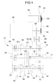
- numerals 10 and 80 indicate, respectively, a mechanical gearbox and an electric machine forming part of a hybrid propulsion system for a motor vehicle also comprising an internal combustion engine (not shown) and a clutch unit (also not shown) forming with the gearbox 10 a double-clutch transmission.
- the gearbox 10 is a gearbox with five forward gears and one reverse gear and comprises:
- the first primary shaft 12 projects axially from the second primary shaft 14 (outer primary shaft) and carries, in order from the side axially opposite to the clutch unit of the transmission (left-hand side relative to the observer of Figure 1 ) to the side axially facing the clutch unit of the transmission (right-hand side relative to the observer of Figure 1 ), a gearwheel 20 acting as driving gearwheel for both the gear train of first gear and the gear train of reverse gear, a gearwheel 22 acting as driving gearwheel for the gear train of fifth gear and a gearwheel 24 acting as driving gearwheel for the gear train of third gear.
- the first primary shaft 12 also carries, at the left-hand end relative to the observer of Figure 1 , an idle gearwheel 26 acting as intermediate gearwheel of a gear train which cinematically connects the lay shaft 18 to the secondary shaft 16, as will be further explained in the following part of the description.
- the second primary shaft 14 carries, in order from left to right relative to the observer of Figure 1 , a gearwheel 28 acting as driving gearwheel for the gear train of fourth gear and a gearwheel 30 acting as driving gearwheel for the gear train of second gear.
- the driving gearwheels 20, 22, 24, 28 and 30 mentioned above are made as fixed gearwheels, i.e. as gearwheels permanently fast for rotation with the respective shafts.
- the secondary shaft 16 carries, at the end axially opposite to the clutch unit, a gearwheel 32 which is made as a fixed gearwheel and permanently meshes with the idle gearwheel 26 of the first primary shaft 12 and, at the end axially facing the clutch unit, a final reduction pinion 34 intended to mesh permanently with an input gearwheel or ring gear of a differential gear of the motor vehicle (not shown).
- a gearwheel 32 which is made as a fixed gearwheel and permanently meshes with the idle gearwheel 26 of the first primary shaft 12 and, at the end axially facing the clutch unit, a final reduction pinion 34 intended to mesh permanently with an input gearwheel or ring gear of a differential gear of the motor vehicle (not shown).
- the secondary shaft 16 also carries between the gearwheel 32 and the final reduction pinion 34, in order from left to right relative to the observer of Figure 1 , a gearwheel 36 permanently meshing with the driving gearwheel 20 and acting as driven gearwheel of the gear train of first gear, a gearwheel 38 permanently meshing with the driving gearwheel 22 and acting as driven gearwheel of the gear train of fifth gear, a gearwheel 40 permanently meshing with the driving gearwheel 28 and acting as driven gearwheel of the gear train of fourth gear, and a gearwheel 42 permanently meshing with the driving gearwheel 30 and acting as driven gearwheel of the gear train of second gear.
- the driven gearwheels 36, 38, 40 and 42 mentioned above are made as idle gearwheels and are selectively connectable for rotation with the secondary shaft 16 by means of a pair of sliding engagement sleeves 44 and 46. More precisely, the engagement sleeve 44 is interposed between the gearwheels 36 and 38 and is selectively movable to the left or to the right, through an intermediate neutral position, to connect the gearwheel 36 or the gearwheel 38, respectively, for rotation with the secondary shaft 16, thereby engaging the first gear or the fifth gear, respectively, whereas the sliding engagement sleeve 46 is interposed between the gearwheels 40 and 42 and is selectively movable to the left or to the right, through an intermediate neutral position, to connect the gearwheel 40 or the gearwheel 42, respectively, for rotation with the secondary shaft 16, thereby engaging the fourth gear or the second gear, respectively.
- the lay shaft 18 carries, at the end axially opposite to the clutch unit, a gearwheel 48 which is made as fixed gearwheel and permanently meshes with the idle gearwheel 26 of the first primary shaft 12, in such a manner that the lay shaft 18 is permanently cinematically connected to the secondary shaft 16 by means of the gear train formed by the gearwheel 48 which is fast for rotation with the lay shaft 18, by the idle gearwheel 26 which is coaxial to the first primary shaft 12 and by the gearwheel 32 which is fast for rotation with the secondary shaft 16.
- the lay shaft 18 also carries, in order from left to right relative to the observer of Figure 1 , a gearwheel 50 permanently meshing with the gearwheel 36 carried by the secondary shaft 16 and acting as intermediate gearwheel of the gear train of reverse gear, a gearwheel 52 permanently meshing with the driving gearwheel 24 carried by the first primary shaft 12 and acting as intermediate gearwheel of the gear train of third gear and a gearwheel 54 acting as parking gearwheel.
- the intermediate gearwheels 50 and 52 mentioned above are made as idle gearwheels, whereas the parking gearwheel 54 is made as fixed gearwheel.
- a sliding engagement sleeve 56 is interposed between the gearwheels 50 and 52 and is selectively movable to the left or to the right, through an intermediate neutral position, to connect the gearwheel 50 or the gearwheel 52, respectively, for rotation with the lay shaft 18, thereby engaging the reverse gear or the third gear, respectively.
- the transmission of the torque in reverse gear and in at least one of the forward gears takes place via the lay shaft 18. More specifically, with the reverse gear engaged (engagement sleeve 56 in the left-hand shift position), the torque is transmitted from the first primary shaft 12 to the lay shaft 18 via the gear train formed by the gearwheel 20 carried by the primary shaft 12 and acting as driving gearwheel, by the gearwheel 36 carried by the secondary shaft 16 and acting as idle gearwheel, and by the gearwheel 50 carried by the lay shaft 18 and acting as driven gearwheel, and then from the lay shaft 18 to the secondary shaft 16 via the gear train formed by the gearwheel 48 carried by the lay shaft 18 and acting as driving gearwheel, by the gearwheel 26 carried by the first primary shaft 12 and acting as idle gearwheel, and by the gearwheel 32 carried by the secondary shaft 16 and acting as driven gearwheel.
- the torque is transmitted from the first primary shaft 12 to the lay shaft 18 via the gear train formed by the gearwheel 24 carried by the primary shaft 12 and acting as driving gearwheel, and by the gearwheel 52 carried by the lay shaft 18 and acting as driven gearwheel, and then from the lay shaft 18 to the secondary shaft 16 via the above-described gear train formed by the gearwheels 48, 26 and 32.
- the gearbox described above with reference to Figure 1 enables to carry out all the single gear shifts in so-called powershift mode, i.e. with the old and new gears engaged at the same time, apart from the gear shift from the first gear to the reverse gear and vice versa, since all the driving gearwheels associated to the odd gears (first, third and fifth gears) are carried by the one primary shaft (in the present case the first primary shaft 12), whereas all the driving gearwheels associated to the even gears (second and fourth gears) are carried by the other primary shaft (in the present case the second primary shaft 14).
- the electric machine 80 is arranged parallel to the gearbox, i.e. with the axis of an output shaft 82 thereof arranged parallel to the axes of the shafts 12, 14, 16 and 18 of the gearbox, and is permanently cinematically connected to either of the primary shafts 12, 14 (in the proposed example to the second primary shaft 14 associated to the even gears) of the gearbox 10 via a gear train consisting of a pinion 84 carried by the output shaft 82 of the electric machine 80, of an intermediate gearwheel 86 carried by a special intermediate shaft 88 (supported by the case of the gearbox 10) and permanently meshing with the pinion 84, and of one of the gearwheels carried by the aforesaid primary shaft 12, 14 of the gearbox (in the example of Figure 1 of the gearwheel 30 acting as driving gearwheel for the gear train of second gear).
- the electric machine 80 is able to perform, in addition to the usual functions of traction (generation of mechanical power for the wheels of the vehicle taking energy from the high-voltage batteries of the vehicle) and of generation (generation of electrical power for the high-voltage batteries of the vehicle taking energy from the recovery of the kinetic energy of the vehicle or from the operation of the internal combustion engine when the vehicle is still), also the functions of alternator and of starting motor, and hence makes it possible to avoid the use of additional alternator and starting motor.
- the electric machine 80 is also connected to a compressor 90 of the air conditioner by means of a driving pulley 92 mounted on the output shaft 82 of the electric machine 80, a driven pulley 94 mounted on a drive shaft 96 of the compressor 90, a belt 98 wound on the two pulleys 92 and 94, and an electromagnetic clutch 100 associated to the driven pulley 94.
- the electric machine 80 is thus able to perform the additional function of generating mechanical power for the compressor 90 of the air conditioner, which is particularly useful as it allows the compressor of the air conditioner to operate also when the internal combustion engine is not running.
- the electric machine 80 and the compressor 90 of the air conditioner (in case of the compressor being connected to the electric machine) can thus be shifted from the side of the internal combustion engine to the side of the gearbox of the motor vehicle.
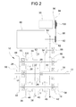
- FIG. 2 A further embodiment of the invention is illustrated in Figure 2 , where parts and elements identical or similar to those of Figure 1 have been given the same reference numerals.
- the gearbox shown in Figure 2 is a gearbox with six forward gears and one reverse gear which also comprises a pair of primary shafts 12 and 14, a secondary shaft 16 and a lay shaft 18.
- the arrangement of the gearwheels associated to the first five forward gears and to the reverse gear is identical to that of the gearbox of Figure 1 , and therefore reference is made to the above detailed description of that gearbox.
- the sixth gear is obtained by adding a sliding engagement sleeve 58 associated to the gearwheel 26 to connect it for rotation with the first primary shaft 12.
- the gearbox according to Figure 2 offers the same advantages mentioned above with reference to the gearbox of Figure 1 , with the difference that in the present case the gear shift from the fifth to the sixth gear, and vice versa, is not allowed in powershift mode, but the gear shift from the sixth to the fourth or second gear during a kick-down manoeuvre is allowed in powershift mode.
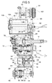
- FIG. 3 A further embodiment of the invention is illustrated in Figure 3 , where parts and elements identical or similar to those of Figure 2 have been given the same reference numerals, increased by 100.
- the gearbox is generally indicated 110 and also comprises a first primary shaft 112 (inner primary shaft), a second primary shaft 114 (outer primary shaft), a secondary shaft 116 and a lay shaft 118.
- the first primary shaft 112 projects axially from the second primary shaft 114 and carries, in order from left to right relative to the observer of Figure 3 , an idle gearwheel 126 acting both as intermediate gearwheel of a gear train which cinematically connects the lay shaft 118 to the secondary shaft 116, and as driving gearwheel for the gear train of third gear, a gearwheel 120 acting as driving gearwheel both for the gear train of first gear and for the gear train of reverse gear, and a gearwheel 122 acting as driving gearwheel for the gear train of fifth gear.
- the second primary shaft 114 carries, in order from left to right relative to the observer of Figure 3 , a gearwheel 124 acting as driving gearwheel for the gear train of fourth gear, a gearwheel 128 acting as driving gearwheel for the gear train of sixth gear and a gearwheel 130 acting as driving gearwheel for the gear train of second gear.
- the above-mentioned driving gearwheels 120, 122, 124, 128 and 130 are made as fixed gearwheels, i.e. they are permanently fast for rotation with the respective shafts.
- the secondary shaft 116 carries, at the end axially opposite to the clutch unit, a gearwheel 132 which is made as fixed gearwheel and permanently meshes with the idle gearwheel 126 of the first primary shaft 112 and, at the end axially facing the clutch unit, a final reduction pinion 134 intended to mesh permanently with an input gearwheel or ring gear of the differential gear of the motor vehicle (not shown).
- the secondary shaft 116 also carries, in order from left to right relative to the observer of Figure 3 , between the gearwheel 132 and the final reduction pinion 134, a gearwheel 136 permanently meshing with the driving gearwheel 120 and acting as driven gearwheel of the gear train of first gear, a gearwheel 138 permanently meshing with the driving gearwheel 122 and acting as driven gearwheel of the gear train of fifth gear, a gearwheel 140 permanently meshing with the driving gearwheel 128 and acting as driven gearwheel of the gear train of sixth gear, and a gearwheel 142 permanently meshing with the driving gearwheel 130 and acting as driven gearwheel of the gear train of second gear.
- the above-mentioned driven gearwheels 136, 138, 140 and 142 are made as idle gearwheels and are selectively connectable for rotation with the secondary shaft 116 by means of a pair of sliding engagement sleeves 144 and 146. More specifically, the sliding engagement sleeve 144 is interposed between the gearwheels 136 and 138 and is selectively movable to the left or to the right to connect the gearwheel 136 or the gearwheel 138, respectively, for rotation with the secondary shaft 116, thereby engaging the first gear or the fifth gear, respectively, whereas the sliding engagement sleeve 146 is interposed between the gearwheels 140 and 142 and is selectively movable to the left or to the right to connect the gearwheel 140 or the gearwheel 142, respectively, for rotation with the secondary shaft 116, thereby engaging the sixth gear or the second gear, respectively.
- the lay shaft 118 carries, at the end axially opposite to the clutch unit, a gearwheel 148 which is made as fixed gearwheel and permanently meshes with the idle gearwheel 126 of the first primary shaft 112, in such a manner that the lay shaft 118 is permanently cinematically connected with the secondary shaft 116 by means of the gear train formed by the gearwheel 148 which is fast for rotation with the lay shaft 118, by the idle gearwheel 126 which is coaxial with the first primary shaft 112 and by the gearwheel 132 which is fast for rotation with the secondary shaft 116.
- the lay shaft 118 also carries, in order from left to right relative to the observer of Figure 3 , a gearwheel 150 permanently meshing with the gearwheel 136 carried by the secondary shaft 116 and acting as intermediate gearwheel of the gear train of reverse gear, a gearwheel 152 permanently meshing with the driving gearwheel 124 carried by the second primary shaft 114 and acting as intermediate gearwheel of the gear train of fourth gear and a gearwheel 154 acting as parking gearwheel.
- the above-mentioned intermediate gearwheels 150 and 152 are made as idle gearwheels, whereas the parking gearwheel 154 is made as fixed gearwheel.
- a sliding engagement sleeve 156 is interposed between the gearwheels 150 and 152 and is selectively movable to the left or to the right to connect the gearwheel 150 or the gearwheel 152, respectively, for rotation with the lay shaft 118, thereby engaging the reverse gear or the fourth gear, respectively.
- the forward gear corresponding to the transmission of the torque via the lay shaft 118 is therefore the fourth gear, instead of the third gear.
- the gear obtained by connecting the idle gearwheel 126 for rotation with the first primary shaft by means of the sliding engagement sleeve 158 is the third gear, instead of the sixth gear.
- the gearbox of Figure 3 makes it possible to carry out all the single gear shifts in powershift mode, apart from the gear shift from the first gear to the reverse gear and vice versa, since all the driving gearwheels associated to the odd gears (first, third and fifth gears) are carried by one primary shaft (also in this case the first primary shaft 112), whereas all the driving gearwheels associated to the even gears (second, fourth and sixth gears) are carried by the other primary shaft (second primary shaft 114). Also the embodiment of Figure 3 offers the same advantages described above in terms of limited axial sizes of the gearbox and of reduced actuation forces of the parking device.
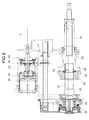
- FIG. 4 A further embodiment of the invention is illustrated in Figure 4 , where parts and elements identical or similar to those of Figure 3 have been given the same reference numerals.
- the gearbox of Figure 4 also comprises a pair of primary shafts 112 and 114, a secondary shaft 116 and a lay shaft 118 and has an arrangement of the gearwheels associated to the six forward gears and to the reverse gear which is identical to that of the gearbox of Figure 3 , the only difference being that the driving gearwheel 128 permanently meshing with the driven gearwheel 140 carried by the secondary shaft 116 to implement the sixth gear is in this case carried by the first primary shaft 112, instead of the second primary shaft 114, and in particular on the right (according to the point of view of the observer of Figure 4 ) of the driving gearwheel 122. Accordingly, the gearbox according to Figure 4 does not allow to shift form the fifth gear to the sixth gear, and vice versa, in powershift mode, but allows anyway to shift from the sixth gear to the fourth or second gear in powershift mode during a kick-down manoeuvre.
- the electric machine is advantageously integrated in the gearbox.
- the electric machine 80 is inserted and fixed into a special seat 102 formed by the case of the gearbox, in such a manner that a spiral-shaped profile 104 of the cooling circuit of the electric machine formed on the outer surface of a stator 106 of the electric machine is closed on the radially outer side by an inner cylindrical surface 108 of the seat 102, the channels of the cooling circuit being therefore defined between the spiral-shaped profile 104 and the inner cylindrical surface 108.
- the transmission according to the invention further comprises a gear shift device arranged to control sequentially the engagement of the gears by controlling the displacement of the engagement sleeves of the gearbox between the respective neutral and shift positions.
- the gear shift device will be described now in combination with the gearbox illustrated in Figures 2 and 5 .
- the gearbox of Figures 2 and 5 is a gearbox with six forward gears and one reverse gear, in which the gears are engaged by means of the four engagement sleeves 44, 46, 56 and 58 associated to the first and fifth gears, to the fourth and second gears, to the reverse and third gears, and finally to the sixth gear, respectively.
- the engagement sleeve 44 can be displaced to the left and to the right, starting from a central neutral position, into a left-hand shift position in which it engages the first gear and into a right-hand shift position in which it engages the fifth gear, respectively
- the engagement sleeve 46 can be displaced to the left and to the right, starting from a central neutral position, into a left-hand shift position in which it engages the fourth gear and into a right-hand shift position in which it engages the second gear, respectively
- the engagement sleeve 56 can be displaced to the left and to the right, starting from a central neutral position, into a left-hand shift position in which it engages the reverse gear and into a right-hand shift position in which it engages the third gear, respectively
- the engagement sleeve 58 can be displaced to the right, starting from a central neutral position, into a right-hand shift position in which it engages the sixth gear.
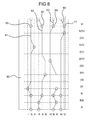
- the gear shift device includes a rotary drum 60, whose axis of rotation (indicated X in Figure 6 ) coincides with the geometrical axis of the drum and is arranged parallel to the axes of the shafts 12, 14, 16 and 18 of the gearbox 10.
- Four guide grooves 61, 62, 63 and 64 are provided, in order from left to right relative to the observer of Figures 5 to 7 , on the outer cylindrical surface of the drum 60.
- a stud 65 slidably engages in the guide groove 61 and is rigidly connected for axial translation (i.e.
- a stud 67 slidably engages in the guide groove 62 and is rigidly connected for axial translation with a shift fork 68, which in turn is rigidly connected for axial translation with the engagement sleeve 56 associated to the reverse and third gears.
- a stud 69 slidably engages in the guide groove 63 and is rigidly connected for axial translation with a shift fork 70, which in turn is rigidly connected for axial translation with the engagement sleeve 46 associated to the fourth and second gears.
- a stud 71 slidably engages in the guide groove 64 and is rigidly connected for axial translation with a shift fork 72, which in turn is rigidly connected for axial translation with the engagement sleeve 58 associated to the sixth gear.
- the shift forks 66 and 70 associated to the engagement sleeves 44 and 46 are slidably mounted along a stationary rod 73, while the shift fork 68 is slidably mounted along a stationary rod 74, the two stationary rods 73 and 74 being fixed to the case of the gearbox 10.
- the shift fork 72 associated to the engagement sleeve 58 is fixed to a sliding rod 75 supported by the case of the gearbox 10. It is however clear that the arrangement of the shift forks and of the respective rods may differ from the one described and illustrated herein.
- the gear shift device further comprises an actuation unit (not shown) arranged to cause the drum 60 to rotate stepwise about the axis of rotation X among a plurality of angular positions each corresponding to predetermined positions of the engagement sleeves 44, 46, 56 and 58.
- the actuation unit includes, in per-se-known manner, an electric motor or a servo-assisted hydraulic device, if necessary coupled to a gear reduction unit.
- the guide grooves 61, 62, 63 and 64 of the drum 60 are suitably shaped in such a manner that they cause each time, as a result of the rotation of the drum, at least one of the studs 65, 67, 69 and 71, and hence at least one of the respective engagement sleeves 44, 56, 46 and 58, to move (axial translation) according to predetermined operating modes to engage or disengage each time one or more gears.
- Figure 8 schematically shows the development in a plane of the guide grooves 61, 62, 63 and 64 of the drum 60 and the positions taken by the studs 65, 67, 69 and 71 (and hence by the engagement sleeves 44, 46, 56 and 58 operatively connected thereto) in each of the angular positions of the drum.
- the angular positions of the drum are indicated on the right side of the scheme of Figure 8 by the symbol of the engaged gear(s).
- the drum takes in sequence the following angular positions in the direction towards the forward gears:
- an intermediate position (II) is provided in which the engagement sleeve 44 is moved into the central neutral position to disengage the first gear, whereas the engagement sleeve 46 remains in the shift position corresponding to the engagement of the second gear.
- an intermediate position (III) is provided in which the engagement sleeve 46 is moved into the central neutral position to disengage the second gear, whereas the engagement sleeve 56 remains in the shift position corresponding to the engagement of the third gear.
- an intermediate position (IV) is provided in which the engagement sleeve 56 is moved into the central neutral position to disengage the third gear, whereas the engagement sleeve 46 remains in the shift position corresponding to the engagement of the fourth gear.
- an intermediate position (IV) is provided in which the engagement sleeve 44 is moved into the central neutral position to disengage the fifth gear, whereas the engagement sleeve 46 remains in the shift position corresponding to the engagement of the fourth gear.
- the drum takes in sequence the following angular positions in the direction towards the reverse gear:
- parking manoeuvres can be performed in powershift mode.
- the second gear and the reverse gear are driven by two different primary shafts, namely the second primary shaft 14 and the first primary shaft 12, respectively, parking manoeuvres can be performed keeping these two gears engaged at the same time and controlling the transmission of the torque in either of these gears by means of the two friction clutches.
- parking manoeuvres can be normally driven by the electric machine or, if necessary, for example in case of exhaustion of the batteries, also by the internal combustion engine.
- the guide grooves of the drum are shaped in such a manner that in one of the angular positions of the drum only the reverse gear is engaged, it is possible, in case of use of the transmission in a hybrid propulsion system with an electric machine permanently cinematically connected to the second primary shaft (even gears), to drive the vehicle in reverse gear by means of the internal combustion engine even in case of breakage of the electric machine.
- the guide grooves of the drum are shaped in such a manner that in one of the angular positions of the drum the sixth gear (associated to the first primary shaft 12) and the fourth gear (associated to the second primary shaft 14) are engaged at the same time, it is possible for the electric machine, in case of use of the transmission in a hybrid propulsion system with an electric machine permanently cinematically connected to the second primary shaft, to operate as a generator when the vehicle is running in sixth gear (motorway gear) to charge the batteries, as well as for the electric machine to be used as a booster. Moreover, the presence of a further angular position of the drum in which only the sixth gear is engaged makes it possible to disconnect the electric machine when the vehicle is running with the sixth gear engaged and the batteries are charged.
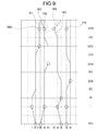
- Figure 9 schematically shows the development in a plane of the outer cylindrical surface of a rotary drum 160 forming part of the gear shift device associated to the gearbox of Figure 3 .
- Four guide grooves 161, 162, 163 and 164 are provided on the outer cylindrical surface of the drum 160, in order from left to right relative to the observer of Figure 9 .
- a stud 165 slidably engages in the guide groove 161 and is rigidly connected for axial translation with the engagement sleeve 144 associated to the first and fifth gears.
- an actuation unit (not shown) is provided to cause the drum 160 to rotate stepwise about its own axis of rotation among a plurality of angular positions each corresponding to predetermined positions of the engagement sleeves 144, 146, 156 and 158.
- the guide grooves 161, 162, 163 and 164 of the drum 160 are suitably shaped in such a manner that they cause each time, as a result of the rotation of the drum, at least one of the studs 165, 167, 169 and 171, and hence at least one of the respective engagement sleeves 144, 156, 146 and 158, to move (axial translation) according to predetermined operating modes to engage or disengage each time one or more gears.
- the drum 160 is arranged to take in sequence the following angular positions:
- an intermediate position (II) is provided in which the engagement sleeve 144 is moved into the central neutral position to disengage the first gear, whereas the engagement sleeve 146 remains in the shift position corresponding to the engagement of the second gear.
- an intermediate position (III) is provided in which the engagement sleeve 146 is moved into the central neutral position to disengage the second gear, whereas the engagement sleeve 158 remains in the shift position corresponding to the engagement of the third gear.
- an intermediate position (IV) is provide in which the engagement sleeve 158 is moved into the central neutral position to disengage the third gear, whereas the engagement sleeve 156 remains in the shift position corresponding to the engagement of the fourth gear.
- an intermediate position (V) is provided in which the engagement sleeve 156 is moved into the central neutral position to disengage the fourth gear, whereas the engagement sleeve 144 remains in the shift position corresponding to the engagement of the fifth gear.
- a gear shift device comprising a drum with guide grooves shaped in such a manner that in one of the angular positions of the drum the second gear and the reverse gear are engaged at the same time can obviously be used also in combination with the gearbox described above with reference to Figure 4 .
Landscapes
- Engineering & Computer Science (AREA)
- Mechanical Engineering (AREA)
- Chemical & Material Sciences (AREA)
- Combustion & Propulsion (AREA)
- Transportation (AREA)
- General Engineering & Computer Science (AREA)
- Structure Of Transmissions (AREA)
Priority Applications (1)
| Application Number | Priority Date | Filing Date | Title |
|---|---|---|---|
| EP11170473.0A EP2375101B1 (de) | 2009-11-13 | 2009-11-13 | Doppelkupplungsgetriebe eines Kraftfahrzeugs mit Gangschaltungsvorrichtung, die eine Drehtrommel umfasst, und Hybridantriebssystem eines Kraftfahrzeugs, das ein solches Getriebe beinhaltet |
Applications Claiming Priority (2)
| Application Number | Priority Date | Filing Date | Title |
|---|---|---|---|
| EP09425460A EP2322822B1 (de) | 2009-11-13 | 2009-11-13 | Doppelkupplungsgetriebe eines Kraftfahrzeugs mit Gangschaltungsvorrichtung, die eine Drehtrommel umfasst, und Hybridantriebssystem eines Kraftfahrzeugs, das ein solches Getriebe beinhaltet |
| EP11170473.0A EP2375101B1 (de) | 2009-11-13 | 2009-11-13 | Doppelkupplungsgetriebe eines Kraftfahrzeugs mit Gangschaltungsvorrichtung, die eine Drehtrommel umfasst, und Hybridantriebssystem eines Kraftfahrzeugs, das ein solches Getriebe beinhaltet |
Related Parent Applications (2)
| Application Number | Title | Priority Date | Filing Date |
|---|---|---|---|
| EP09425460A Division EP2322822B1 (de) | 2009-11-13 | 2009-11-13 | Doppelkupplungsgetriebe eines Kraftfahrzeugs mit Gangschaltungsvorrichtung, die eine Drehtrommel umfasst, und Hybridantriebssystem eines Kraftfahrzeugs, das ein solches Getriebe beinhaltet |
| EP09425460.4 Division | 2009-11-13 |
Publications (3)
| Publication Number | Publication Date |
|---|---|
| EP2375101A2 true EP2375101A2 (de) | 2011-10-12 |
| EP2375101A3 EP2375101A3 (de) | 2012-05-02 |
| EP2375101B1 EP2375101B1 (de) | 2015-01-14 |
Family
ID=41718562
Family Applications (2)
| Application Number | Title | Priority Date | Filing Date |
|---|---|---|---|
| EP09425460A Not-in-force EP2322822B1 (de) | 2009-11-13 | 2009-11-13 | Doppelkupplungsgetriebe eines Kraftfahrzeugs mit Gangschaltungsvorrichtung, die eine Drehtrommel umfasst, und Hybridantriebssystem eines Kraftfahrzeugs, das ein solches Getriebe beinhaltet |
| EP11170473.0A Not-in-force EP2375101B1 (de) | 2009-11-13 | 2009-11-13 | Doppelkupplungsgetriebe eines Kraftfahrzeugs mit Gangschaltungsvorrichtung, die eine Drehtrommel umfasst, und Hybridantriebssystem eines Kraftfahrzeugs, das ein solches Getriebe beinhaltet |
Family Applications Before (1)
| Application Number | Title | Priority Date | Filing Date |
|---|---|---|---|
| EP09425460A Not-in-force EP2322822B1 (de) | 2009-11-13 | 2009-11-13 | Doppelkupplungsgetriebe eines Kraftfahrzeugs mit Gangschaltungsvorrichtung, die eine Drehtrommel umfasst, und Hybridantriebssystem eines Kraftfahrzeugs, das ein solches Getriebe beinhaltet |
Country Status (4)
| Country | Link |
|---|---|
| US (2) | US20110113922A1 (de) |
| EP (2) | EP2322822B1 (de) |
| CN (2) | CN102062178B (de) |
| AT (1) | ATE548587T1 (de) |
Families Citing this family (21)
| Publication number | Priority date | Publication date | Assignee | Title |
|---|---|---|---|---|
| DE102008000637A1 (de) * | 2008-03-13 | 2009-09-17 | Zf Friedrichshafen Ag | Betätigungsanordnung eines zentralsynchronisierten Doppelkupplungsgetriebe |
| EP2322822B1 (de) * | 2009-11-13 | 2012-03-07 | C.R.F. Società Consortile per Azioni | Doppelkupplungsgetriebe eines Kraftfahrzeugs mit Gangschaltungsvorrichtung, die eine Drehtrommel umfasst, und Hybridantriebssystem eines Kraftfahrzeugs, das ein solches Getriebe beinhaltet |
| US10550920B2 (en) * | 2010-12-17 | 2020-02-04 | Dti Group B.V. | Transmission system, as well as method for changing a transmission ratio |
| EP2760692B1 (de) * | 2011-09-30 | 2018-12-05 | BRP-Rotax GmbH & Co. KG | Antriebsaggregat für hybridkraftfahrzeug |
| EP2600039A1 (de) * | 2011-11-30 | 2013-06-05 | C.R.F. Società Consortile per Azioni | Gangwechselvorrichtung für ein Kraftfahrzeug |
| KR101327864B1 (ko) * | 2011-12-23 | 2013-11-11 | 대동공업주식회사 | 전기구동식 다목적 운반차량의 변속충격 저감 시스템 |
| KR101362059B1 (ko) * | 2012-12-10 | 2014-02-12 | 현대자동차 주식회사 | 더블 클러치 변속기 |
| WO2015117610A1 (de) * | 2014-02-07 | 2015-08-13 | Schaeffler Technologies AG & Co. KG | Betätigungsvorrichtung mit wenigstens zwei schaltwalzen in kompakter anordnung sowie schaltgetriebe |
| CN106143102B (zh) * | 2014-11-18 | 2019-07-16 | 上海汽车集团股份有限公司 | 车辆混合动力驱动系统及其变速器 |
| CN105673780B (zh) | 2014-11-18 | 2019-08-06 | 上海汽车集团股份有限公司 | 车辆混合动力驱动系统及其变速器 |
| CN105667491B (zh) | 2014-11-18 | 2019-07-16 | 上海汽车集团股份有限公司 | 用于混合动力车辆变速器的控制系统和方法 |
| US10252613B2 (en) | 2016-01-22 | 2019-04-09 | Team Industries, Inc. | Dual clutch transaxle |
| US10626929B2 (en) | 2016-05-09 | 2020-04-21 | Team Industries, Inc. | Dual clutch |
| CN106515418B (zh) * | 2016-11-11 | 2018-11-27 | 上海中科深江电动车辆有限公司 | 换挡机构及混合动力装置 |
| CN106585356B (zh) * | 2016-12-21 | 2018-12-25 | 上海中科深江电动车辆有限公司 | 混合动力装置及其操控方法 |
| DE102017009029B4 (de) * | 2017-09-27 | 2019-11-21 | Daimler Ag | Kraftfahrzeuggetriebe, insbesondere für einen Kraftwagen |
| CN107795675B (zh) * | 2017-11-27 | 2023-10-13 | 智新科技股份有限公司 | 一种汽车双离合变速箱的新型选换档装置 |
| IT201900004213A1 (it) * | 2019-03-22 | 2020-09-22 | Piaggio & C Spa | Cambio di trasmissione di un veicolo a sella cavalcabile |
| DE102019110044A1 (de) * | 2019-04-16 | 2020-10-22 | Schaeffler Technologies AG & Co. KG | Schalteinrichtung für ein hybrides Antriebssystem eines Kraftfahrzeuges; Antriebssystem sowie Kraftfahrzeug |
| WO2021021479A1 (en) * | 2019-07-26 | 2021-02-04 | Polaris Industries Inc. | Automated sequential transmissions |
| CN111173925A (zh) * | 2020-01-22 | 2020-05-19 | 凯博易控车辆科技(苏州)股份有限公司 | 一种变速器的换挡机构、换挡方法和车辆 |
Family Cites Families (33)
| Publication number | Priority date | Publication date | Assignee | Title |
|---|---|---|---|---|
| DE3037990A1 (de) * | 1980-10-08 | 1982-05-13 | Volkswagenwerk Ag, 3180 Wolfsburg | Zahnraedergetriebe |
| DE19727569A1 (de) * | 1997-06-28 | 1999-01-07 | Schaeffler Waelzlager Ohg | Schaltwalze für ein Zahnräderwechselgetriebe |
| DE19800880A1 (de) * | 1998-01-13 | 1999-04-29 | Bosch Gmbh Robert | Schaltvorrichtung für ein mehrgängiges Wechselgetriebe |
| US6012561A (en) * | 1998-09-15 | 2000-01-11 | Chrysler Corporation | Dual clutch design for and electro-mechanical automatic transmission having a dual input shaft |
| US6286381B1 (en) * | 1999-12-17 | 2001-09-11 | Daimlerchrysler Corporation | Gear preselect system for an electro-mechanical automatic transmission having dual input shafts |
| DE10011271B4 (de) * | 2000-03-08 | 2009-04-09 | Daimler Ag | Stufengetriebe mit einer Schalt- und Wählvorrichtung |
| DE10165097B3 (de) * | 2000-07-18 | 2015-07-23 | Schaeffler Technologies AG & Co. KG | Doppelkupplungsgetriebe |
| IT1315661B1 (it) * | 2000-08-10 | 2003-03-14 | Automac Sas Di Bigi Ing Mauriz | Dispositivo per il comando sequenziale di cambi con azionamento aselezione ed innesto per veicoli a motore |
| DE10209514B4 (de) * | 2001-03-30 | 2016-06-09 | Schaeffler Technologies AG & Co. KG | Antriebsstrang |
| DE10128853A1 (de) * | 2001-06-15 | 2002-12-19 | Zf Sachs Ag | Kraftfahrzeug und Verfahren zum Betrieb des Fahrzeugs, insbesondere zum Freischaukeln oder/und Rangieren |
| JP2003336701A (ja) * | 2002-05-22 | 2003-11-28 | Hitachi Ltd | 自動変速機 |
| US6766705B1 (en) * | 2003-01-24 | 2004-07-27 | General Motors Corporation | Seven-speed power transmission |
| DE10305241A1 (de) * | 2003-02-08 | 2004-09-23 | Zf Friedrichshafen Ag | Sechs- oder siebengängiges Doppelkupplungsgetriebe |
| KR100569140B1 (ko) * | 2003-12-10 | 2006-04-07 | 현대자동차주식회사 | 이중 클러치 변속기 |
| KR100634589B1 (ko) * | 2003-12-24 | 2006-10-13 | 현대자동차주식회사 | 하이브리드 전기자동차용 이중 클러치 변속기 및 그모드별 작동방법 |
| US7082850B2 (en) * | 2003-12-30 | 2006-08-01 | Eaton Corporation | Hybrid powertrain system |
| EP1681497A3 (de) * | 2005-01-15 | 2010-03-10 | LuK Lamellen und Kupplungsbau Beteiligungs KG | Verfahren zur Steuerung eines Doppelkupplungsgetriebes |
| DE602005003461T2 (de) * | 2005-06-09 | 2008-09-25 | C.R.F. Società Consortile per Azioni, Orbassano | Doppelkupplungsgetriebe für Kraftfahrzeug |
| CN2835716Y (zh) * | 2005-09-26 | 2006-11-08 | 春风控股集团有限公司 | 一种全场地车发动机换档结构 |
| US7467564B2 (en) * | 2006-03-13 | 2008-12-23 | Ford Global Technologies, Llc | Actuator mechanism for shift motors of a transmission |
| US7428852B2 (en) * | 2006-03-13 | 2008-09-30 | Ford Global Technologies, Llc | Actuator mechanism for shift motors of a transmission |
| JP2007285363A (ja) * | 2006-04-13 | 2007-11-01 | Aisin Ai Co Ltd | 歯車式自動変速機のシフト装置 |
| EP2109724B1 (de) * | 2007-01-16 | 2013-02-27 | BorgWarner, Inc. | Getriebe mit doppelkupplung |
| JP2008202640A (ja) * | 2007-02-16 | 2008-09-04 | Aisin Ai Co Ltd | 歯車変速装置 |
| US7752936B2 (en) * | 2007-03-06 | 2010-07-13 | Honda Motor Co., Ltd. | Automatic transmission assembly for a vehicle, and vehicle incorporating same |
| JP4897534B2 (ja) * | 2007-03-28 | 2012-03-14 | 本田技研工業株式会社 | 車両用変速機 |
| JP4970183B2 (ja) * | 2007-07-27 | 2012-07-04 | 本田技研工業株式会社 | 車両用変速機 |
| JP5211741B2 (ja) * | 2008-02-19 | 2013-06-12 | いすゞ自動車株式会社 | 変速機の変速操作装置 |
| US8056429B2 (en) * | 2008-04-02 | 2011-11-15 | GM Global Technology Operations LLC | Multi-speed dual clutch transmission with countershaft gearing arrangement |
| DE102008039452B3 (de) * | 2008-08-25 | 2010-04-01 | Gertrag Ford Transmissions Gmbh | Verfahren zum Steuern eines automatisierten Schaltgetriebes |
| JP4607222B2 (ja) * | 2009-01-27 | 2011-01-05 | 本田技研工業株式会社 | ハイブリッド車両 |
| US8402859B2 (en) * | 2009-11-04 | 2013-03-26 | GM Global Technology Operations LLC | Barrel cam shift mechanism |
| EP2322822B1 (de) * | 2009-11-13 | 2012-03-07 | C.R.F. Società Consortile per Azioni | Doppelkupplungsgetriebe eines Kraftfahrzeugs mit Gangschaltungsvorrichtung, die eine Drehtrommel umfasst, und Hybridantriebssystem eines Kraftfahrzeugs, das ein solches Getriebe beinhaltet |
-
2009
- 2009-11-13 EP EP09425460A patent/EP2322822B1/de not_active Not-in-force
- 2009-11-13 EP EP11170473.0A patent/EP2375101B1/de not_active Not-in-force
- 2009-11-13 AT AT09425460T patent/ATE548587T1/de active
-
2010
- 2010-05-14 US US12/780,586 patent/US20110113922A1/en not_active Abandoned
- 2010-06-11 CN CN2010102026120A patent/CN102062178B/zh not_active Expired - Fee Related
- 2010-06-11 CN CN201110343016.9A patent/CN102506130B/zh not_active Expired - Fee Related
-
2012
- 2012-10-11 US US13/649,864 patent/US20130091984A1/en not_active Abandoned
Non-Patent Citations (1)
| Title |
|---|
| None |
Also Published As
| Publication number | Publication date |
|---|---|
| US20130091984A1 (en) | 2013-04-18 |
| US20110113922A1 (en) | 2011-05-19 |
| EP2375101A3 (de) | 2012-05-02 |
| EP2322822A1 (de) | 2011-05-18 |
| EP2375101B1 (de) | 2015-01-14 |
| CN102062178A (zh) | 2011-05-18 |
| EP2322822B1 (de) | 2012-03-07 |
| CN102506130B (zh) | 2015-09-09 |
| CN102062178B (zh) | 2013-08-28 |
| CN102506130A (zh) | 2012-06-20 |
| ATE548587T1 (de) | 2012-03-15 |
Similar Documents
| Publication | Publication Date | Title |
|---|---|---|
| EP2375101B1 (de) | Doppelkupplungsgetriebe eines Kraftfahrzeugs mit Gangschaltungsvorrichtung, die eine Drehtrommel umfasst, und Hybridantriebssystem eines Kraftfahrzeugs, das ein solches Getriebe beinhaltet | |
| EP2322371B1 (de) | Hybrides Motorfahrzeugantriebssystem mit Doppelkupplungsgetriebe mit einer Schaltvorrichtung mit Drehtrommel | |
| EP2322372B1 (de) | Hybridantriebssystem für ein Motorfahrzeug | |
| EP2752325B1 (de) | Hybridgetriebe für ein Kraftfahrzeug | |
| CN102348568B (zh) | 混合动力车辆用动力传递装置 | |
| CN102348567B (zh) | 动力传递装置 | |
| US8522635B2 (en) | Hybrid propulsion system for a motor vehicle with a double-drum gear control device | |
| KR101481304B1 (ko) | Dct를 구비한 하이브리드 파워트레인 | |
| US9744840B2 (en) | Power transmission apparatus for vehicle | |
| KR101294089B1 (ko) | 차량용 변속장치 | |
| US20150211607A1 (en) | Transmission for hybrid vehicle | |
| KR101338458B1 (ko) | 차량용 변속장치 | |
| KR101294090B1 (ko) | 차량용 변속장치 | |
| KR102809281B1 (ko) | 차량용 동력 유닛 및 차량용 동력 유닛을 동작시키는 방법 | |
| WO2017168377A1 (en) | Transmission system for a hybrid propulsion vehicle | |
| KR101339248B1 (ko) | 차량용 변속장치 | |
| CN216374160U (zh) | 一种变速器 | |
| CN115704446A (zh) | 用于机动车的变速器以及具有这种变速器的传动系和机动车 |
Legal Events
| Date | Code | Title | Description |
|---|---|---|---|
| PUAI | Public reference made under article 153(3) epc to a published international application that has entered the european phase |
Free format text: ORIGINAL CODE: 0009012 |
|
| AC | Divisional application: reference to earlier application |
Ref document number: 2322822 Country of ref document: EP Kind code of ref document: P |
|
| AK | Designated contracting states |
Kind code of ref document: A2 Designated state(s): AT BE BG CH CY CZ DE DK EE ES FI FR GB GR HR HU IE IS IT LI LT LU LV MC MK MT NL NO PL PT RO SE SI SK SM TR |
|
| AX | Request for extension of the european patent |
Extension state: AL BA RS |
|
| PUAL | Search report despatched |
Free format text: ORIGINAL CODE: 0009013 |
|
| AK | Designated contracting states |
Kind code of ref document: A3 Designated state(s): AT BE BG CH CY CZ DE DK EE ES FI FR GB GR HR HU IE IS IT LI LT LU LV MC MK MT NL NO PL PT RO SE SI SK SM TR |
|
| AX | Request for extension of the european patent |
Extension state: AL BA RS |
|
| RIC1 | Information provided on ipc code assigned before grant |
Ipc: F16H 63/18 20060101ALI20120329BHEP Ipc: F16H 3/00 20060101AFI20120329BHEP Ipc: B60K 6/36 20071001ALI20120329BHEP |
|
| 17P | Request for examination filed |
Effective date: 20121029 |
|
| GRAP | Despatch of communication of intention to grant a patent |
Free format text: ORIGINAL CODE: EPIDOSNIGR1 |
|
| INTG | Intention to grant announced |
Effective date: 20140728 |
|
| GRAS | Grant fee paid |
Free format text: ORIGINAL CODE: EPIDOSNIGR3 |
|
| GRAA | (expected) grant |
Free format text: ORIGINAL CODE: 0009210 |
|
| AC | Divisional application: reference to earlier application |
Ref document number: 2322822 Country of ref document: EP Kind code of ref document: P |
|
| AK | Designated contracting states |
Kind code of ref document: B1 Designated state(s): AT BE BG CH CY CZ DE DK EE ES FI FR GB GR HR HU IE IS IT LI LT LU LV MC MK MT NL NO PL PT RO SE SI SK SM TR |
|
| REG | Reference to a national code |
Ref country code: GB Ref legal event code: FG4D |
|
| REG | Reference to a national code |
Ref country code: CH Ref legal event code: EP |
|
| REG | Reference to a national code |
Ref country code: IE Ref legal event code: FG4D |
|
| REG | Reference to a national code |
Ref country code: AT Ref legal event code: REF Ref document number: 707237 Country of ref document: AT Kind code of ref document: T Effective date: 20150215 |
|
| REG | Reference to a national code |
Ref country code: DE Ref legal event code: R096 Ref document number: 602009029043 Country of ref document: DE Effective date: 20150305 |
|
| REG | Reference to a national code |
Ref country code: NL Ref legal event code: VDEP Effective date: 20150114 |
|
| REG | Reference to a national code |
Ref country code: AT Ref legal event code: MK05 Ref document number: 707237 Country of ref document: AT Kind code of ref document: T Effective date: 20150114 |
|
| REG | Reference to a national code |
Ref country code: LT Ref legal event code: MG4D |
|
| PG25 | Lapsed in a contracting state [announced via postgrant information from national office to epo] |
Ref country code: SE Free format text: LAPSE BECAUSE OF FAILURE TO SUBMIT A TRANSLATION OF THE DESCRIPTION OR TO PAY THE FEE WITHIN THE PRESCRIBED TIME-LIMIT Effective date: 20150114 Ref country code: HR Free format text: LAPSE BECAUSE OF FAILURE TO SUBMIT A TRANSLATION OF THE DESCRIPTION OR TO PAY THE FEE WITHIN THE PRESCRIBED TIME-LIMIT Effective date: 20150114 Ref country code: FI Free format text: LAPSE BECAUSE OF FAILURE TO SUBMIT A TRANSLATION OF THE DESCRIPTION OR TO PAY THE FEE WITHIN THE PRESCRIBED TIME-LIMIT Effective date: 20150114 Ref country code: BG Free format text: LAPSE BECAUSE OF FAILURE TO SUBMIT A TRANSLATION OF THE DESCRIPTION OR TO PAY THE FEE WITHIN THE PRESCRIBED TIME-LIMIT Effective date: 20150414 Ref country code: NO Free format text: LAPSE BECAUSE OF FAILURE TO SUBMIT A TRANSLATION OF THE DESCRIPTION OR TO PAY THE FEE WITHIN THE PRESCRIBED TIME-LIMIT Effective date: 20150414 Ref country code: ES Free format text: LAPSE BECAUSE OF FAILURE TO SUBMIT A TRANSLATION OF THE DESCRIPTION OR TO PAY THE FEE WITHIN THE PRESCRIBED TIME-LIMIT Effective date: 20150114 Ref country code: LT Free format text: LAPSE BECAUSE OF FAILURE TO SUBMIT A TRANSLATION OF THE DESCRIPTION OR TO PAY THE FEE WITHIN THE PRESCRIBED TIME-LIMIT Effective date: 20150114 |
|
| PG25 | Lapsed in a contracting state [announced via postgrant information from national office to epo] |
Ref country code: PL Free format text: LAPSE BECAUSE OF FAILURE TO SUBMIT A TRANSLATION OF THE DESCRIPTION OR TO PAY THE FEE WITHIN THE PRESCRIBED TIME-LIMIT Effective date: 20150114 Ref country code: LV Free format text: LAPSE BECAUSE OF FAILURE TO SUBMIT A TRANSLATION OF THE DESCRIPTION OR TO PAY THE FEE WITHIN THE PRESCRIBED TIME-LIMIT Effective date: 20150114 Ref country code: AT Free format text: LAPSE BECAUSE OF FAILURE TO SUBMIT A TRANSLATION OF THE DESCRIPTION OR TO PAY THE FEE WITHIN THE PRESCRIBED TIME-LIMIT Effective date: 20150114 Ref country code: GR Free format text: LAPSE BECAUSE OF FAILURE TO SUBMIT A TRANSLATION OF THE DESCRIPTION OR TO PAY THE FEE WITHIN THE PRESCRIBED TIME-LIMIT Effective date: 20150415 Ref country code: NL Free format text: LAPSE BECAUSE OF FAILURE TO SUBMIT A TRANSLATION OF THE DESCRIPTION OR TO PAY THE FEE WITHIN THE PRESCRIBED TIME-LIMIT Effective date: 20150114 Ref country code: IS Free format text: LAPSE BECAUSE OF FAILURE TO SUBMIT A TRANSLATION OF THE DESCRIPTION OR TO PAY THE FEE WITHIN THE PRESCRIBED TIME-LIMIT Effective date: 20150514 |
|
| REG | Reference to a national code |
Ref country code: DE Ref legal event code: R097 Ref document number: 602009029043 Country of ref document: DE |
|
| PG25 | Lapsed in a contracting state [announced via postgrant information from national office to epo] |
Ref country code: SK Free format text: LAPSE BECAUSE OF FAILURE TO SUBMIT A TRANSLATION OF THE DESCRIPTION OR TO PAY THE FEE WITHIN THE PRESCRIBED TIME-LIMIT Effective date: 20150114 Ref country code: EE Free format text: LAPSE BECAUSE OF FAILURE TO SUBMIT A TRANSLATION OF THE DESCRIPTION OR TO PAY THE FEE WITHIN THE PRESCRIBED TIME-LIMIT Effective date: 20150114 Ref country code: CZ Free format text: LAPSE BECAUSE OF FAILURE TO SUBMIT A TRANSLATION OF THE DESCRIPTION OR TO PAY THE FEE WITHIN THE PRESCRIBED TIME-LIMIT Effective date: 20150114 Ref country code: RO Free format text: LAPSE BECAUSE OF FAILURE TO SUBMIT A TRANSLATION OF THE DESCRIPTION OR TO PAY THE FEE WITHIN THE PRESCRIBED TIME-LIMIT Effective date: 20150114 Ref country code: DK Free format text: LAPSE BECAUSE OF FAILURE TO SUBMIT A TRANSLATION OF THE DESCRIPTION OR TO PAY THE FEE WITHIN THE PRESCRIBED TIME-LIMIT Effective date: 20150114 |
|
| PLBE | No opposition filed within time limit |
Free format text: ORIGINAL CODE: 0009261 |
|
| STAA | Information on the status of an ep patent application or granted ep patent |
Free format text: STATUS: NO OPPOSITION FILED WITHIN TIME LIMIT |
|
| REG | Reference to a national code |
Ref country code: FR Ref legal event code: PLFP Year of fee payment: 7 |
|
| 26N | No opposition filed |
Effective date: 20151015 |
|
| PG25 | Lapsed in a contracting state [announced via postgrant information from national office to epo] |
Ref country code: SI Free format text: LAPSE BECAUSE OF FAILURE TO SUBMIT A TRANSLATION OF THE DESCRIPTION OR TO PAY THE FEE WITHIN THE PRESCRIBED TIME-LIMIT Effective date: 20150114 |
|
| PG25 | Lapsed in a contracting state [announced via postgrant information from national office to epo] |
Ref country code: BE Free format text: LAPSE BECAUSE OF FAILURE TO SUBMIT A TRANSLATION OF THE DESCRIPTION OR TO PAY THE FEE WITHIN THE PRESCRIBED TIME-LIMIT Effective date: 20150114 |
|
| PG25 | Lapsed in a contracting state [announced via postgrant information from national office to epo] |
Ref country code: MC Free format text: LAPSE BECAUSE OF FAILURE TO SUBMIT A TRANSLATION OF THE DESCRIPTION OR TO PAY THE FEE WITHIN THE PRESCRIBED TIME-LIMIT Effective date: 20150114 Ref country code: LU Free format text: LAPSE BECAUSE OF FAILURE TO SUBMIT A TRANSLATION OF THE DESCRIPTION OR TO PAY THE FEE WITHIN THE PRESCRIBED TIME-LIMIT Effective date: 20151113 |
|
| REG | Reference to a national code |
Ref country code: CH Ref legal event code: PL |
|
| GBPC | Gb: european patent ceased through non-payment of renewal fee |
Effective date: 20151113 |
|
| PG25 | Lapsed in a contracting state [announced via postgrant information from national office to epo] |
Ref country code: LI Free format text: LAPSE BECAUSE OF NON-PAYMENT OF DUE FEES Effective date: 20151130 Ref country code: CH Free format text: LAPSE BECAUSE OF NON-PAYMENT OF DUE FEES Effective date: 20151130 |
|
| REG | Reference to a national code |
Ref country code: IE Ref legal event code: MM4A |
|
| PG25 | Lapsed in a contracting state [announced via postgrant information from national office to epo] |
Ref country code: IE Free format text: LAPSE BECAUSE OF NON-PAYMENT OF DUE FEES Effective date: 20151113 Ref country code: GB Free format text: LAPSE BECAUSE OF NON-PAYMENT OF DUE FEES Effective date: 20151113 |
|
| REG | Reference to a national code |
Ref country code: FR Ref legal event code: PLFP Year of fee payment: 8 |
|
| PG25 | Lapsed in a contracting state [announced via postgrant information from national office to epo] |
Ref country code: HU Free format text: LAPSE BECAUSE OF FAILURE TO SUBMIT A TRANSLATION OF THE DESCRIPTION OR TO PAY THE FEE WITHIN THE PRESCRIBED TIME-LIMIT; INVALID AB INITIO Effective date: 20091113 Ref country code: SM Free format text: LAPSE BECAUSE OF FAILURE TO SUBMIT A TRANSLATION OF THE DESCRIPTION OR TO PAY THE FEE WITHIN THE PRESCRIBED TIME-LIMIT Effective date: 20150114 |
|
| PG25 | Lapsed in a contracting state [announced via postgrant information from national office to epo] |
Ref country code: CY Free format text: LAPSE BECAUSE OF FAILURE TO SUBMIT A TRANSLATION OF THE DESCRIPTION OR TO PAY THE FEE WITHIN THE PRESCRIBED TIME-LIMIT Effective date: 20150114 |
|
| PG25 | Lapsed in a contracting state [announced via postgrant information from national office to epo] |
Ref country code: MT Free format text: LAPSE BECAUSE OF FAILURE TO SUBMIT A TRANSLATION OF THE DESCRIPTION OR TO PAY THE FEE WITHIN THE PRESCRIBED TIME-LIMIT Effective date: 20150114 Ref country code: TR Free format text: LAPSE BECAUSE OF FAILURE TO SUBMIT A TRANSLATION OF THE DESCRIPTION OR TO PAY THE FEE WITHIN THE PRESCRIBED TIME-LIMIT Effective date: 20150114 |
|
| REG | Reference to a national code |
Ref country code: FR Ref legal event code: PLFP Year of fee payment: 9 |
|
| PG25 | Lapsed in a contracting state [announced via postgrant information from national office to epo] |
Ref country code: MK Free format text: LAPSE BECAUSE OF FAILURE TO SUBMIT A TRANSLATION OF THE DESCRIPTION OR TO PAY THE FEE WITHIN THE PRESCRIBED TIME-LIMIT Effective date: 20150114 Ref country code: PT Free format text: LAPSE BECAUSE OF FAILURE TO SUBMIT A TRANSLATION OF THE DESCRIPTION OR TO PAY THE FEE WITHIN THE PRESCRIBED TIME-LIMIT Effective date: 20150114 |
|
| RIC2 | Information provided on ipc code assigned after grant |
Ipc: F16H 3/00 20060101AFI20120329BHEP Ipc: F16H 63/18 20060101ALI20120329BHEP Ipc: B60K 6/36 20071001ALI20120329BHEP |
|
| PGFP | Annual fee paid to national office [announced via postgrant information from national office to epo] |
Ref country code: DE Payment date: 20201130 Year of fee payment: 12 Ref country code: IT Payment date: 20201109 Year of fee payment: 12 Ref country code: FR Payment date: 20201130 Year of fee payment: 12 |
|
| REG | Reference to a national code |
Ref country code: DE Ref legal event code: R119 Ref document number: 602009029043 Country of ref document: DE |
|
| PG25 | Lapsed in a contracting state [announced via postgrant information from national office to epo] |
Ref country code: DE Free format text: LAPSE BECAUSE OF NON-PAYMENT OF DUE FEES Effective date: 20220601 |
|
| PG25 | Lapsed in a contracting state [announced via postgrant information from national office to epo] |
Ref country code: FR Free format text: LAPSE BECAUSE OF NON-PAYMENT OF DUE FEES Effective date: 20211130 |
|
| PG25 | Lapsed in a contracting state [announced via postgrant information from national office to epo] |
Ref country code: IT Free format text: LAPSE BECAUSE OF NON-PAYMENT OF DUE FEES Effective date: 20211113 |