EP2375207A2 - Kühlerkondensatsystem - Google Patents
Kühlerkondensatsystem Download PDFInfo
- Publication number
- EP2375207A2 EP2375207A2 EP11159010A EP11159010A EP2375207A2 EP 2375207 A2 EP2375207 A2 EP 2375207A2 EP 11159010 A EP11159010 A EP 11159010A EP 11159010 A EP11159010 A EP 11159010A EP 2375207 A2 EP2375207 A2 EP 2375207A2
- Authority
- EP
- European Patent Office
- Prior art keywords
- condensate
- chiller
- flow
- heat exchanger
- load
- Prior art date
- Legal status (The legal status is an assumption and is not a legal conclusion. Google has not performed a legal analysis and makes no representation as to the accuracy of the status listed.)
- Withdrawn
Links
- 238000004891 communication Methods 0.000 claims abstract description 12
- 238000001816 cooling Methods 0.000 claims description 43
- 239000007921 spray Substances 0.000 claims description 23
- 238000004378 air conditioning Methods 0.000 claims description 10
- 239000012530 fluid Substances 0.000 claims description 3
- 239000007789 gas Substances 0.000 description 20
- XLYOFNOQVPJJNP-UHFFFAOYSA-N water Substances O XLYOFNOQVPJJNP-UHFFFAOYSA-N 0.000 description 11
- 230000037361 pathway Effects 0.000 description 7
- 239000000446 fuel Substances 0.000 description 6
- 238000000605 extraction Methods 0.000 description 4
- VNWKTOKETHGBQD-UHFFFAOYSA-N methane Chemical compound C VNWKTOKETHGBQD-UHFFFAOYSA-N 0.000 description 4
- 239000010687 lubricating oil Substances 0.000 description 3
- 239000004909 Moisturizer Substances 0.000 description 2
- 239000000567 combustion gas Substances 0.000 description 2
- 230000001333 moisturizer Effects 0.000 description 2
- 239000003345 natural gas Substances 0.000 description 2
- 238000013461 design Methods 0.000 description 1
- 230000000694 effects Effects 0.000 description 1
- 239000003595 mist Substances 0.000 description 1
- 239000000203 mixture Substances 0.000 description 1
- 238000012986 modification Methods 0.000 description 1
- 230000004048 modification Effects 0.000 description 1
- 238000012552 review Methods 0.000 description 1
- 229920006395 saturated elastomer Polymers 0.000 description 1
- 238000012546 transfer Methods 0.000 description 1
Images


Classifications
-
- F—MECHANICAL ENGINEERING; LIGHTING; HEATING; WEAPONS; BLASTING
- F28—HEAT EXCHANGE IN GENERAL
- F28F—DETAILS OF HEAT-EXCHANGE AND HEAT-TRANSFER APPARATUS, OF GENERAL APPLICATION
- F28F17/00—Removing ice or water from heat-exchange apparatus
- F28F17/005—Means for draining condensates from heat exchangers, e.g. from evaporators
-
- F—MECHANICAL ENGINEERING; LIGHTING; HEATING; WEAPONS; BLASTING
- F01—MACHINES OR ENGINES IN GENERAL; ENGINE PLANTS IN GENERAL; STEAM ENGINES
- F01D—NON-POSITIVE DISPLACEMENT MACHINES OR ENGINES, e.g. STEAM TURBINES
- F01D25/00—Component parts, details, or accessories, not provided for in, or of interest apart from, other groups
- F01D25/08—Cooling; Heating; Heat-insulation
- F01D25/12—Cooling
-
- F—MECHANICAL ENGINEERING; LIGHTING; HEATING; WEAPONS; BLASTING
- F02—COMBUSTION ENGINES; HOT-GAS OR COMBUSTION-PRODUCT ENGINE PLANTS
- F02C—GAS-TURBINE PLANTS; AIR INTAKES FOR JET-PROPULSION PLANTS; CONTROLLING FUEL SUPPLY IN AIR-BREATHING JET-PROPULSION PLANTS
- F02C7/00—Features, components parts, details or accessories, not provided for in, or of interest apart form groups F02C1/00 - F02C6/00; Air intakes for jet-propulsion plants
- F02C7/12—Cooling of plants
-
- F—MECHANICAL ENGINEERING; LIGHTING; HEATING; WEAPONS; BLASTING
- F02—COMBUSTION ENGINES; HOT-GAS OR COMBUSTION-PRODUCT ENGINE PLANTS
- F02C—GAS-TURBINE PLANTS; AIR INTAKES FOR JET-PROPULSION PLANTS; CONTROLLING FUEL SUPPLY IN AIR-BREATHING JET-PROPULSION PLANTS
- F02C7/00—Features, components parts, details or accessories, not provided for in, or of interest apart form groups F02C1/00 - F02C6/00; Air intakes for jet-propulsion plants
- F02C7/12—Cooling of plants
- F02C7/14—Cooling of plants of fluids in the plant, e.g. lubricant or fuel
- F02C7/141—Cooling of plants of fluids in the plant, e.g. lubricant or fuel of working fluid
- F02C7/143—Cooling of plants of fluids in the plant, e.g. lubricant or fuel of working fluid before or between the compressor stages
-
- F—MECHANICAL ENGINEERING; LIGHTING; HEATING; WEAPONS; BLASTING
- F02—COMBUSTION ENGINES; HOT-GAS OR COMBUSTION-PRODUCT ENGINE PLANTS
- F02C—GAS-TURBINE PLANTS; AIR INTAKES FOR JET-PROPULSION PLANTS; CONTROLLING FUEL SUPPLY IN AIR-BREATHING JET-PROPULSION PLANTS
- F02C7/00—Features, components parts, details or accessories, not provided for in, or of interest apart form groups F02C1/00 - F02C6/00; Air intakes for jet-propulsion plants
- F02C7/12—Cooling of plants
- F02C7/14—Cooling of plants of fluids in the plant, e.g. lubricant or fuel
- F02C7/141—Cooling of plants of fluids in the plant, e.g. lubricant or fuel of working fluid
- F02C7/143—Cooling of plants of fluids in the plant, e.g. lubricant or fuel of working fluid before or between the compressor stages
- F02C7/1435—Cooling of plants of fluids in the plant, e.g. lubricant or fuel of working fluid before or between the compressor stages by water injection
-
- F—MECHANICAL ENGINEERING; LIGHTING; HEATING; WEAPONS; BLASTING
- F28—HEAT EXCHANGE IN GENERAL
- F28C—HEAT-EXCHANGE APPARATUS, NOT PROVIDED FOR IN ANOTHER SUBCLASS, IN WHICH THE HEAT-EXCHANGE MEDIA COME INTO DIRECT CONTACT WITHOUT CHEMICAL INTERACTION
- F28C1/00—Direct-contact trickle coolers, e.g. cooling towers
-
- F—MECHANICAL ENGINEERING; LIGHTING; HEATING; WEAPONS; BLASTING
- F28—HEAT EXCHANGE IN GENERAL
- F28C—HEAT-EXCHANGE APPARATUS, NOT PROVIDED FOR IN ANOTHER SUBCLASS, IN WHICH THE HEAT-EXCHANGE MEDIA COME INTO DIRECT CONTACT WITHOUT CHEMICAL INTERACTION
- F28C3/00—Other direct-contact heat-exchange apparatus
- F28C3/06—Other direct-contact heat-exchange apparatus the heat-exchange media being a liquid and a gas or vapour
-
- F—MECHANICAL ENGINEERING; LIGHTING; HEATING; WEAPONS; BLASTING
- F28—HEAT EXCHANGE IN GENERAL
- F28D—HEAT-EXCHANGE APPARATUS, NOT PROVIDED FOR IN ANOTHER SUBCLASS, IN WHICH THE HEAT-EXCHANGE MEDIA DO NOT COME INTO DIRECT CONTACT
- F28D21/00—Heat-exchange apparatus not covered by any of the groups F28D1/00 - F28D20/00
- F28D21/0001—Recuperative heat exchangers
- F28D21/0012—Recuperative heat exchangers the heat being recuperated from waste water or from condensates
-
- F—MECHANICAL ENGINEERING; LIGHTING; HEATING; WEAPONS; BLASTING
- F05—INDEXING SCHEMES RELATING TO ENGINES OR PUMPS IN VARIOUS SUBCLASSES OF CLASSES F01-F04
- F05D—INDEXING SCHEME FOR ASPECTS RELATING TO NON-POSITIVE-DISPLACEMENT MACHINES OR ENGINES, GAS-TURBINES OR JET-PROPULSION PLANTS
- F05D2260/00—Function
- F05D2260/60—Fluid transfer
- F05D2260/602—Drainage
-
- Y—GENERAL TAGGING OF NEW TECHNOLOGICAL DEVELOPMENTS; GENERAL TAGGING OF CROSS-SECTIONAL TECHNOLOGIES SPANNING OVER SEVERAL SECTIONS OF THE IPC; TECHNICAL SUBJECTS COVERED BY FORMER USPC CROSS-REFERENCE ART COLLECTIONS [XRACs] AND DIGESTS
- Y02—TECHNOLOGIES OR APPLICATIONS FOR MITIGATION OR ADAPTATION AGAINST CLIMATE CHANGE
- Y02B—CLIMATE CHANGE MITIGATION TECHNOLOGIES RELATED TO BUILDINGS, e.g. HOUSING, HOUSE APPLIANCES OR RELATED END-USER APPLICATIONS
- Y02B30/00—Energy efficient heating, ventilation or air conditioning [HVAC]
- Y02B30/56—Heat recovery units
-
- Y—GENERAL TAGGING OF NEW TECHNOLOGICAL DEVELOPMENTS; GENERAL TAGGING OF CROSS-SECTIONAL TECHNOLOGIES SPANNING OVER SEVERAL SECTIONS OF THE IPC; TECHNICAL SUBJECTS COVERED BY FORMER USPC CROSS-REFERENCE ART COLLECTIONS [XRACs] AND DIGESTS
- Y02—TECHNOLOGIES OR APPLICATIONS FOR MITIGATION OR ADAPTATION AGAINST CLIMATE CHANGE
- Y02B—CLIMATE CHANGE MITIGATION TECHNOLOGIES RELATED TO BUILDINGS, e.g. HOUSING, HOUSE APPLIANCES OR RELATED END-USER APPLICATIONS
- Y02B30/00—Energy efficient heating, ventilation or air conditioning [HVAC]
- Y02B30/70—Efficient control or regulation technologies, e.g. for control of refrigerant flow, motor or heating
Definitions
- the present application relates generally to gas turbine engines and more particularly relates to a gas turbine engine with a chiller condensate system used for cooling purposes.
- the power output of a gas turbine engine is directly proportional to the inlet air mass flow rate.
- the inlet air mass depends upon the density of the inlet air and hence the temperature of the air.
- known gas turbine engines may use a chiller system to lower the air temperature about the compressor inlet. By lowering the inlet air temperature, the density of the inlet air may be increased and the mass flow rate to the compressor may increase. The power output of the gas turbine engine thus increases due to the higher mass flow rate.
- Sensible heat transfer from the inlet air to the low temperature water circulating through the chiller coils cools the inlet air.
- the condensate is drained and collected so as to avoid carryover downstream and into the compressor.
- the condensate generally is discharged to the atmosphere or otherwise disposed.
- the temperature of the condensate may be around about fifty (50) to about sixty (60) degrees Fahrenheit (about ten (10) to about 15.6 degrees Celsius) although other temperatures may be used. If a typical chiller system is operating at full load, the volume of the condensate may be at about 75 gallons per minute (about 284 liters per minute). Other condensate volumes may be used.
- the present application thus provides a chiller condensate system.
- the chiller condensate system may include a chiller that produces a flow of condensate, a condensate drain system positioned about the chiller to collect the flow of condensate, and a heat exchanger in communication with the condensate drain system for the condensate to flow therethrough.
- the present application thus provides a chiller condensate system.
- the chiller condensate system may include a chiller that produces a flow of condensate, a condensate drain system positioned about the chiller to collect the flow of condensate, and a nozzle in communication with the condensate drain system for the condensate to spray therethrough.
- the present application further provides a cooling tower.
- the cooling tower may include a chiller condensate system with a nozzle to provide a spray of condensate and a closed cooling circuit.
- the spray of condensate may chill the closed cooling circuit.
- Fig. 1 shows a schematic view of a gas turbine engine 100.
- the gas turbine engine 100 may include a compressor 110 to compress an incoming flow of air.
- the compressor 110 delivers the compressed flow of air to a combustor 120.
- the combustor 120 mixes the compressed flow of air with a compressed flow of fuel and ignites the mixture.
- the gas turbine engine 100 may include any number of combustors 120.
- the hot combustion gases are in turn delivered to a turbine 130.
- the hot combustion gases drive the turbine 130 so as to produce mechanical work.
- the mechanical work produced in the turbine 130 drives the compressor 110 and an external load 140 such as an electrical generator and the like.
- the gas turbine engine 100 may use natural gas, various types of syngas, and other types of fuels. Other gas turbine engine configurations may be used herein.
- the gas turbine engine 100 also may include a chiller system 150.
- the chiller system 150 may be positioned about the inlet of the compressor 110. As described above, the chiller system 150 chills an incoming airflow 160 to a desired temperature.
- Various types of chiller systems 150 are known.
- Fig. 2 shows an improved chiller system 170 as is described herein.
- the chiller system 170 may include a number of coils 180. As described above, water flows through the coils 180 so as to chill the incoming airflow 160.
- the chiller system 170 also may include a condensate drain system 190.
- the condensate drain system may include a coil drain 200 positioned about each of the coils 180. A flow of condensate 210 passes on to each coil drain 200.
- the coil drain 200 may take the form of a trough or a similar structure to catch the condensate.
- the coil drains 200 may lead to a condensate pipe 220 or other type of central basin. As described above, the flow of condensate 210 may be at about 75 gallons per minute (about 284 liters per minute). Other condensate volumes may be used herein.
- Fig. 3 shows an example of a chiller condensate system 230 as is claimed herein.
- the chiller condensate system 230 may be in the form of a condensate heat exchange system 235.
- the condensate heat exchange system 235 includes the chiller system 170 with the condensate drain system 190.
- the flow of condensate 210 from the coil drains 200 is forwarded to a heat exchanger 240 by the condensate pipe 220.
- the heat exchanger 240 may be any type of heat exchange device including shell and tube heat exchangers, plate heat exchangers, plate and fin heat exchangers, air coils, direct contact, adiabatic heat exchangers, etc.
- the heat exchanger 240 exchanges heat with any type of load 245 such as an airflow, a turbine component, or other structure in a manner similar to those examples described below.
- a pump 250 may be positioned about the condensate pipe 220. The flow of condensate 210 may then flow to additional heat exchangers 240, discharged, or otherwise used.
- Fig. 4 shows use of the condensate heat exchanger system 235 with an example of a load 245, an air conditioning system 260.
- the heat exchanger 240 of the condensate heat exchanger system 235 may be positioned about a fan 270 or other type of air movement device of the air conditioning system 260.
- the heat exchanger 240 may cool an air conditioning flow 280 therethrough.
- the condensate heat exchanger system 235 thus uses the flow of condensate 210 to provide cooling in the form of air conditioning.
- the use of the condensate heat exchanger system 235 thus reduces the need for externally generated chilled water that may be used exclusively for air conditioning purposes.
- Other air conditioning configurations and systems may be used herein.
- Fig. 5 shows the use of the condensate heat exchanger system 235 with a steam turbine condenser 290.
- the heat exchanger 240 thus may take the form of tubes or other types of pathways through the condenser 290.
- a vacuum is maintained in the steam turbine condenser 290 by expanding a flow of steam passing through a steam pathway 300 therein.
- the expansion may maintain the vacuum.
- the back pressure in the condenser 290 may be reduced. With lower back pressure, the steam may expand to a lower temperature and thus provide more output.
- the flow of condensate 210 also may be added to an existing ambient flow through the condenser 290.
- Other steam turbine condenser configurations and other structures may be used herein.
- Fig. 6 shows the use of the condensate heat exchanger system 235 with a turbine compartment 310.
- the turbine compartment 310 may be an enclosure of any shape with turbine equipment therein. Heat from the turbine casing and other components may cause safety and lifetime issues for the equipment therein.
- the turbine compartment 310 thus may include a cooling air pathway 320 extending therethrough.
- the heat exchanger 240 of the condensate heat exchanger system 235 may be positioned about the cooling air pathway 320 or otherwise to chill an incoming flow of air 325 along the cooling air pathway 320. Alternatively, the heat exchanger 240 may be positioned about any of the specific pieces of equipment therein.
- Other turbine compartment configurations may be used herein.
- Fig. 7 shows use of the condensate heat exchanger system 235 with an exhaust frame and bearing system 330.
- the exhaust frame and bearing system 330 may include a bearing housing 340 supporting a rotor 350.
- the bearing housing 340 may be positioned within an exhaust frame 360 with a hot gas path 370 extending therethrough.
- the exhaust frame and bearing system 330 also may include a cooling air pathway 380 extending therethrough to cool the bearing housing 340 and the exhaust frame 360 with an incoming flow of air 385.
- the heat exchanger 240 of the condenser heat exchanger system 235 may be positioned about the cooling air pathway 380 to cool the incoming airflow 385. Further, the heat exchanger 240 may be positioned elsewhere within the exhaust frame and bearing system 330. Cooling may increase the lifespan of the bearing housing 340, the exhaust frame 360, and the other components therein. Other exhaust frame and bearing system configurations may be used herein.
- Fig. 8 shows the use of the condensate heat exchanger system 235 with a nozzle cooling system 390.
- Air extracted from, for example, a ninth stage 400 and the eleventh stage 410 of the compressor 110 may be used to cool a stage three nozzle 420 and a stage two nozzle 430 of the turbine 130 via a number of extraction lines 440.
- the heat exchanger 240 of the condensate heat exchanger system 235 may be positioned about the extraction lines 440 so as to cool an air extraction 450 therein. Better cooling of the nozzles 420, 430 thus may increase component lifetime.
- the heat exchanger 240 also may be positioned elsewhere about the nozzle cooling system 390. Likewise, other types of extractions may be used. Other types of nozzle cooling configurations also may be used herein.
- the chiller condensate system 230 also may be used with a fuel moisturizer 455.
- Fuel moisturization systems have been used in combined cycle power plants in an attempt to increase power output and thermodynamic efficiency. In such systems, natural gas is saturated with water and the moisturized fuel is heated to saturation conditions at the design gas pressure. The increased gas mass flow due to the addition of moisture may result in increased power output from gas and steam turbines.
- the flow of condensate 210 may be directed to the saturator 455 to saturate a flow of fuel therein.
- the flow of condensate 210 may flow directly to the saturator 445, exchange heat with the heat exchanger 240, or otherwise be warmed. Such moisturization may improve the overall efficiency of the gas turbine engine 100.
- the pump 250 also may be used herein.
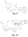
- Fig. 9 shows a further example of the chiller condensate system 230.
- the chiller condensate system 230 may be in the form of a condensate spray system 460 as may be described herein.
- the condensate spray system 460 may include one or more spray nozzles 470 so as to provide a spray 480 of the condensate 210 for cooling purposes to a load 490 in a manner similar to the heat exchanger 240.
- the spray nozzles 470 may be any type of device that provides the spray 480 in any form.
- the spray 480 may take the form of a mist, a stream, or any type of output.
- the spray nozzles 470 also may be positioned downstream of the heat exchanger 240 for use therewith. Other positions and components may be used herein.
- the pump 250 also may be used herein.
- Fig. 10 shows the use of the condensate spray system 460 with a cooling tower 500.
- the cooling tower 500 may include a water tube bundle 510 extending therethrough. (Although only one water tube is shown herein, the water tube bundle 510 may have any number of tubes.)
- the water tube bundle 510 may be part of a closed cooling circuit 520.
- the closed cooling circuit 520 may include one or more heat exchangers 530. Any type of heat exchanger or heat exchange device may be used herein.
- the water tube bundle 510 may be cooled by an incoming airflow 540 drawn in by a number of fans 550 or other types of air movement devices positioned within the cooling tower 500.
- One or more nozzles 470 of the condensate spray system 460 may be positioned about the airflow 540 so as to provide the spray 480 to the airflow 540. Cooling the airflow 540 with the spray 480 of the condensate 210 may further cool the water tube bundle 510. As such, the overall operation of the heat exchanger 530 and the closed cooling circuit 520 may be improved.
- the heat exchanger 530 of the closed cooling circuit 520 may be used to cool any type of further load 560 such as a fluid flow, a component, and the like.
- the heat exchanger 530 may be a lube oil heat exchanger, a generator heat exchanger or cooler, a steam condenser, or any type of component for heat exchange therewith.
- Better cooling of the lube oil may increase the lube oil life and varnishing may be avoided.
- additional cooling for the generator may raise the efficiency of the generator.
- better cooling of the condenser may increase output due to better expansion of the steam. Other benefits of additional (and free) cooling may be found herein.
- the condensate heat exchanger system 235 and/or the condensate spray system 460 of the chiller condensate system 230 thus may be used to cool any component within the gas turbine engine 100 as well as related components such as power plant air conditioning and other types of loads 245. Such cooling provided by otherwise discarded condensate thus serves to improve the overall efficiency of the gas turbine engine system 100.
Landscapes
- Engineering & Computer Science (AREA)
- Mechanical Engineering (AREA)
- General Engineering & Computer Science (AREA)
- Chemical & Material Sciences (AREA)
- Combustion & Propulsion (AREA)
- Physics & Mathematics (AREA)
- Thermal Sciences (AREA)
- Engine Equipment That Uses Special Cycles (AREA)
- Other Air-Conditioning Systems (AREA)
- Sorption Type Refrigeration Machines (AREA)
Applications Claiming Priority (1)
| Application Number | Priority Date | Filing Date | Title |
|---|---|---|---|
| US12/730,334 US20110232313A1 (en) | 2010-03-24 | 2010-03-24 | Chiller Condensate System |
Publications (2)
| Publication Number | Publication Date |
|---|---|
| EP2375207A2 true EP2375207A2 (de) | 2011-10-12 |
| EP2375207A3 EP2375207A3 (de) | 2014-02-26 |
Family
ID=44484110
Family Applications (1)
| Application Number | Title | Priority Date | Filing Date |
|---|---|---|---|
| EP11159010.5A Withdrawn EP2375207A3 (de) | 2010-03-24 | 2011-03-21 | Kühlerkondensatsystem |
Country Status (3)
| Country | Link |
|---|---|
| US (1) | US20110232313A1 (de) |
| EP (1) | EP2375207A3 (de) |
| JP (1) | JP2011202657A (de) |
Families Citing this family (7)
| Publication number | Priority date | Publication date | Assignee | Title |
|---|---|---|---|---|
| CN103321879A (zh) * | 2012-03-22 | 2013-09-25 | 简明堃 | 气体供应装置 |
| CA2885161A1 (en) * | 2012-10-16 | 2014-04-24 | Loren K. Starcher | Increasing combustibility of low btu natural gas |
| US20140123623A1 (en) * | 2012-11-08 | 2014-05-08 | General Electric Company | Gas turbomachine system including an inlet chiller condensate recovery system |
| US20160237902A1 (en) * | 2013-11-05 | 2016-08-18 | Jianmin Zhang | Gas turbine inlet air conditioning coil system |
| US10082083B2 (en) * | 2015-12-22 | 2018-09-25 | General Electric Company | False start drain system with vertical header |
| US10443898B2 (en) | 2016-10-28 | 2019-10-15 | Ingersoll-Rand Company | Air compressor system including a refrigerated dryer and a condensate harvester and water supply |
| CN117288000B (zh) * | 2023-11-22 | 2024-02-13 | 山东华科环境科技有限公司 | 一种节水的冷却塔水雾回收装置 |
Family Cites Families (16)
| Publication number | Priority date | Publication date | Assignee | Title |
|---|---|---|---|---|
| US3895499A (en) * | 1974-05-29 | 1975-07-22 | Borg Warner | Absorption refrigeration system and method |
| US4660390A (en) * | 1986-03-25 | 1987-04-28 | Worthington Mark N | Air conditioner with three stages of indirect regeneration |
| US4760423A (en) * | 1987-03-12 | 1988-07-26 | Savin Corporation | Apparatus and method for reducing hydrocarbon emissions from a liquid-based electrophotographic copying machine |
| US5419146A (en) * | 1994-04-28 | 1995-05-30 | American Standard Inc. | Evaporator water temperature control for a chiller system |
| DE60033738T2 (de) * | 1999-07-01 | 2007-11-08 | General Electric Co. | Vorrichtung zur Befeuchtung und Heizung von Brenngas |
| US6318065B1 (en) * | 1999-08-06 | 2001-11-20 | Tom L. Pierson | System for chilling inlet air for gas turbines |
| TW445360B (en) * | 2000-08-02 | 2001-07-11 | Nutec Electrical Eng Co Ltd | Air-conditioning apparatus with evaporative type condenser |
| US6412291B1 (en) * | 2000-09-05 | 2002-07-02 | Donald C. Erickson | Air compression improvement |
| US6457315B1 (en) * | 2000-12-07 | 2002-10-01 | Ipsi, Llc | Hybrid refrigeration cycle for combustion turbine inlet air cooling |
| US6739119B2 (en) * | 2001-12-31 | 2004-05-25 | Donald C. Erickson | Combustion engine improvement |
| US7013658B2 (en) * | 2004-02-03 | 2006-03-21 | Carrier Corporation | Refrigerant subcooling by condensate |
| US20080092579A1 (en) * | 2006-10-18 | 2008-04-24 | Viking Range Corporation | Refrigerator Condensation Removal System |
| KR100831850B1 (ko) * | 2006-12-14 | 2008-05-22 | 모딘코리아 유한회사 | 열교환기 |
| CN101568782A (zh) * | 2006-12-26 | 2009-10-28 | 开利公司 | 改进冷凝物去除的热交换器 |
| US7762054B2 (en) * | 2007-08-21 | 2010-07-27 | Donald Charles Erickson | Thermally powered turbine inlet air chiller heater |
| US7966802B2 (en) * | 2008-02-05 | 2011-06-28 | General Electric Company | Methods and apparatus for operating gas turbine engine systems |
-
2010
- 2010-03-24 US US12/730,334 patent/US20110232313A1/en not_active Abandoned
-
2011
- 2011-03-21 EP EP11159010.5A patent/EP2375207A3/de not_active Withdrawn
- 2011-03-22 JP JP2011062673A patent/JP2011202657A/ja not_active Withdrawn
Non-Patent Citations (1)
| Title |
|---|
| None |
Also Published As
| Publication number | Publication date |
|---|---|
| EP2375207A3 (de) | 2014-02-26 |
| JP2011202657A (ja) | 2011-10-13 |
| US20110232313A1 (en) | 2011-09-29 |
Similar Documents
| Publication | Publication Date | Title |
|---|---|---|
| EP2375207A2 (de) | Kühlerkondensatsystem | |
| CN101059101B (zh) | 燃气轮机进口调节系统和方法 | |
| US9719423B2 (en) | Inlet air chilling system with humidity control and energy recovery | |
| KR101459142B1 (ko) | 일체형 플랜트 냉각 시스템 | |
| JP5072994B2 (ja) | 風力発電装置 | |
| US20080304954A1 (en) | Highly Supercharged Gas Turbine Generating System | |
| US6422019B1 (en) | Apparatus for augmenting power produced from gas turbines | |
| US20110113781A1 (en) | System and method for secondary energy production in a compressed air energy storage system | |
| US20130239542A1 (en) | Structures and methods for intercooling aircraft gas turbine engines | |
| EP3396118B1 (de) | Zwischengekühlte turbine mit wärmespeichersystem | |
| US20190078513A1 (en) | Humid air turbine power, water extraction, and refrigeration cycle | |
| ITMI941519A1 (it) | Metodo ed apparecchio per aumentare la potenza prodotta da turbina a gas | |
| KR930019989A (ko) | 가스 터어빈 그룹을 작동하는 방법 | |
| JP2013160233A (ja) | ガスタービン入口空気加熱システム及び方法 | |
| WO2011005343A1 (en) | Combined cycle power plant | |
| US6119445A (en) | Method of and apparatus for augmenting power produced from gas turbines | |
| CN101660452A (zh) | 用于涡轮机的热管中间冷却器 | |
| CN101749120A (zh) | 用于涡轮机的冷却系统 | |
| CN104350257A (zh) | 燃气涡轮控制系统及方法 | |
| JP4992346B2 (ja) | ヒートポンプシステム、ヒートポンプシステムの軸封方法 | |
| CN101749286B (zh) | 深制冷空气洗涤器 | |
| Hatamiya et al. | An evaluation of advanced humid air turbine system with water recovery | |
| JP5433590B2 (ja) | ガスタービンシステム | |
| JP2013024079A (ja) | 吸気噴霧型ガスタービン及び高湿分空気利用型ガスタービン | |
| Baghirov | Supersonic cooling technology of gas turbine air |
Legal Events
| Date | Code | Title | Description |
|---|---|---|---|
| PUAI | Public reference made under article 153(3) epc to a published international application that has entered the european phase |
Free format text: ORIGINAL CODE: 0009012 |
|
| AK | Designated contracting states |
Kind code of ref document: A2 Designated state(s): AL AT BE BG CH CY CZ DE DK EE ES FI FR GB GR HR HU IE IS IT LI LT LU LV MC MK MT NL NO PL PT RO RS SE SI SK SM TR |
|
| AX | Request for extension of the european patent |
Extension state: BA ME |
|
| PUAL | Search report despatched |
Free format text: ORIGINAL CODE: 0009013 |
|
| AK | Designated contracting states |
Kind code of ref document: A3 Designated state(s): AL AT BE BG CH CY CZ DE DK EE ES FI FR GB GR HR HU IE IS IT LI LT LU LV MC MK MT NL NO PL PT RO RS SE SI SK SM TR |
|
| AX | Request for extension of the european patent |
Extension state: BA ME |
|
| RIC1 | Information provided on ipc code assigned before grant |
Ipc: F02C 7/143 20060101ALI20140123BHEP Ipc: F28D 21/00 20060101ALI20140123BHEP Ipc: F28C 1/00 20060101AFI20140123BHEP Ipc: F02C 7/16 20060101ALI20140123BHEP Ipc: F28C 3/06 20060101ALI20140123BHEP Ipc: F01D 25/12 20060101ALN20140123BHEP Ipc: F02C 7/12 20060101ALN20140123BHEP Ipc: F28F 17/00 20060101ALI20140123BHEP |
|
| STAA | Information on the status of an ep patent application or granted ep patent |
Free format text: STATUS: THE APPLICATION IS DEEMED TO BE WITHDRAWN |
|
| 18D | Application deemed to be withdrawn |
Effective date: 20140827 |