EP2375281A1 - Multiplexeur optique et laser à fibre - Google Patents
Multiplexeur optique et laser à fibre Download PDFInfo
- Publication number
- EP2375281A1 EP2375281A1 EP10733403A EP10733403A EP2375281A1 EP 2375281 A1 EP2375281 A1 EP 2375281A1 EP 10733403 A EP10733403 A EP 10733403A EP 10733403 A EP10733403 A EP 10733403A EP 2375281 A1 EP2375281 A1 EP 2375281A1
- Authority
- EP
- European Patent Office
- Prior art keywords
- wavelength
- light
- output
- laser
- optical multiplexer
- Prior art date
- Legal status (The legal status is an assumption and is not a legal conclusion. Google has not performed a legal analysis and makes no representation as to the accuracy of the status listed.)
- Withdrawn
Links
Images




Classifications
-
- H—ELECTRICITY
- H01—ELECTRIC ELEMENTS
- H01S—DEVICES USING THE PROCESS OF LIGHT AMPLIFICATION BY STIMULATED EMISSION OF RADIATION [LASER] TO AMPLIFY OR GENERATE LIGHT; DEVICES USING STIMULATED EMISSION OF ELECTROMAGNETIC RADIATION IN WAVE RANGES OTHER THAN OPTICAL
- H01S3/00—Lasers, i.e. devices using stimulated emission of electromagnetic radiation in the infrared, visible or ultraviolet wave range
- H01S3/30—Lasers, i.e. devices using stimulated emission of electromagnetic radiation in the infrared, visible or ultraviolet wave range using scattering effects, e.g. stimulated Brillouin or Raman effects
- H01S3/302—Lasers, i.e. devices using stimulated emission of electromagnetic radiation in the infrared, visible or ultraviolet wave range using scattering effects, e.g. stimulated Brillouin or Raman effects in an optical fibre
-
- H—ELECTRICITY
- H04—ELECTRIC COMMUNICATION TECHNIQUE
- H04B—TRANSMISSION
- H04B10/00—Transmission systems employing electromagnetic waves other than radio-waves, e.g. infrared, visible or ultraviolet light, or employing corpuscular radiation, e.g. quantum communication
- H04B10/29—Repeaters
- H04B10/291—Repeaters in which processing or amplification is carried out without conversion of the main signal from optical form
- H04B10/2912—Repeaters in which processing or amplification is carried out without conversion of the main signal from optical form characterised by the medium used for amplification or processing
- H04B10/2916—Repeaters in which processing or amplification is carried out without conversion of the main signal from optical form characterised by the medium used for amplification or processing using Raman or Brillouin amplifiers
-
- G—PHYSICS
- G02—OPTICS
- G02F—OPTICAL DEVICES OR ARRANGEMENTS FOR THE CONTROL OF LIGHT BY MODIFICATION OF THE OPTICAL PROPERTIES OF THE MEDIA OF THE ELEMENTS INVOLVED THEREIN; NON-LINEAR OPTICS; FREQUENCY-CHANGING OF LIGHT; OPTICAL LOGIC ELEMENTS; OPTICAL ANALOGUE/DIGITAL CONVERTERS
- G02F1/00—Devices or arrangements for the control of the intensity, colour, phase, polarisation or direction of light arriving from an independent light source, e.g. switching, gating or modulating; Non-linear optics
- G02F1/35—Non-linear optics
- G02F1/353—Frequency conversion, i.e. wherein a light beam is generated with frequency components different from those of the incident light beams
-
- G—PHYSICS
- G02—OPTICS
- G02F—OPTICAL DEVICES OR ARRANGEMENTS FOR THE CONTROL OF LIGHT BY MODIFICATION OF THE OPTICAL PROPERTIES OF THE MEDIA OF THE ELEMENTS INVOLVED THEREIN; NON-LINEAR OPTICS; FREQUENCY-CHANGING OF LIGHT; OPTICAL LOGIC ELEMENTS; OPTICAL ANALOGUE/DIGITAL CONVERTERS
- G02F2203/00—Function characteristic
- G02F2203/58—Multi-wavelength, e.g. operation of the device at a plurality of wavelengths
- G02F2203/585—Add/drop devices
-
- H—ELECTRICITY
- H01—ELECTRIC ELEMENTS
- H01S—DEVICES USING THE PROCESS OF LIGHT AMPLIFICATION BY STIMULATED EMISSION OF RADIATION [LASER] TO AMPLIFY OR GENERATE LIGHT; DEVICES USING STIMULATED EMISSION OF ELECTROMAGNETIC RADIATION IN WAVE RANGES OTHER THAN OPTICAL
- H01S3/00—Lasers, i.e. devices using stimulated emission of electromagnetic radiation in the infrared, visible or ultraviolet wave range
- H01S3/05—Construction or shape of optical resonators; Accommodation of active medium therein; Shape of active medium
- H01S3/06—Construction or shape of active medium
- H01S3/063—Waveguide lasers, i.e. whereby the dimensions of the waveguide are of the order of the light wavelength
- H01S3/067—Fibre lasers
- H01S3/06708—Constructional details of the fibre, e.g. compositions, cross-section, shape or tapering
- H01S3/06729—Peculiar transverse fibre profile
-
- H—ELECTRICITY
- H01—ELECTRIC ELEMENTS
- H01S—DEVICES USING THE PROCESS OF LIGHT AMPLIFICATION BY STIMULATED EMISSION OF RADIATION [LASER] TO AMPLIFY OR GENERATE LIGHT; DEVICES USING STIMULATED EMISSION OF ELECTROMAGNETIC RADIATION IN WAVE RANGES OTHER THAN OPTICAL
- H01S3/00—Lasers, i.e. devices using stimulated emission of electromagnetic radiation in the infrared, visible or ultraviolet wave range
- H01S3/05—Construction or shape of optical resonators; Accommodation of active medium therein; Shape of active medium
- H01S3/06—Construction or shape of active medium
- H01S3/063—Waveguide lasers, i.e. whereby the dimensions of the waveguide are of the order of the light wavelength
- H01S3/067—Fibre lasers
- H01S3/06708—Constructional details of the fibre, e.g. compositions, cross-section, shape or tapering
- H01S3/06729—Peculiar transverse fibre profile
- H01S3/06741—Photonic crystal fibre, i.e. the fibre having a photonic bandgap
-
- H—ELECTRICITY
- H01—ELECTRIC ELEMENTS
- H01S—DEVICES USING THE PROCESS OF LIGHT AMPLIFICATION BY STIMULATED EMISSION OF RADIATION [LASER] TO AMPLIFY OR GENERATE LIGHT; DEVICES USING STIMULATED EMISSION OF ELECTROMAGNETIC RADIATION IN WAVE RANGES OTHER THAN OPTICAL
- H01S3/00—Lasers, i.e. devices using stimulated emission of electromagnetic radiation in the infrared, visible or ultraviolet wave range
- H01S3/09—Processes or apparatus for excitation, e.g. pumping
- H01S3/091—Processes or apparatus for excitation, e.g. pumping using optical pumping
- H01S3/094—Processes or apparatus for excitation, e.g. pumping using optical pumping by coherent light
- H01S3/094096—Multi-wavelength pumping
-
- H—ELECTRICITY
- H01—ELECTRIC ELEMENTS
- H01S—DEVICES USING THE PROCESS OF LIGHT AMPLIFICATION BY STIMULATED EMISSION OF RADIATION [LASER] TO AMPLIFY OR GENERATE LIGHT; DEVICES USING STIMULATED EMISSION OF ELECTROMAGNETIC RADIATION IN WAVE RANGES OTHER THAN OPTICAL
- H01S3/00—Lasers, i.e. devices using stimulated emission of electromagnetic radiation in the infrared, visible or ultraviolet wave range
- H01S3/10—Controlling the intensity, frequency, phase, polarisation or direction of the emitted radiation, e.g. switching, gating, modulating or demodulating
- H01S3/10007—Controlling the intensity, frequency, phase, polarisation or direction of the emitted radiation, e.g. switching, gating, modulating or demodulating in optical amplifiers
- H01S3/10015—Controlling the intensity, frequency, phase, polarisation or direction of the emitted radiation, e.g. switching, gating, modulating or demodulating in optical amplifiers by monitoring or controlling, e.g. attenuating, the input signal
-
- H—ELECTRICITY
- H01—ELECTRIC ELEMENTS
- H01S—DEVICES USING THE PROCESS OF LIGHT AMPLIFICATION BY STIMULATED EMISSION OF RADIATION [LASER] TO AMPLIFY OR GENERATE LIGHT; DEVICES USING STIMULATED EMISSION OF ELECTROMAGNETIC RADIATION IN WAVE RANGES OTHER THAN OPTICAL
- H01S3/00—Lasers, i.e. devices using stimulated emission of electromagnetic radiation in the infrared, visible or ultraviolet wave range
- H01S3/14—Lasers, i.e. devices using stimulated emission of electromagnetic radiation in the infrared, visible or ultraviolet wave range characterised by the material used as the active medium
- H01S3/16—Solid materials
- H01S3/1601—Solid materials characterised by an active (lasing) ion
- H01S3/1603—Solid materials characterised by an active (lasing) ion rare earth
- H01S3/1618—Solid materials characterised by an active (lasing) ion rare earth ytterbium
Definitions
- the present invention relates to an optical multiplexer and a fiber laser, and especially relates to the optical multiplexer and the fiber laser for providing a high-output fiber laser with an excellent beam quality.
- Such high-output fiber laser is increasingly used industrially in various fields such as a processor, a medical device and a measuring device, and especially, in a field of material processing, since the fiber laser may perform precision processing because this is more excellent in a light collecting property than other lasers, power density of which is high and this may obtain a small beam spot, and since this performs non-contact processing and this may also perform processing of a hard material, which may absorb laser light, application thereof is rapidly enlarged.
- the coherent beam system generates phase coupling to multiplex by adjusting phases of a plurality of laser output lights oscillated at the same wavelength (for example, refer to the patent document 1). According to this, high-output light of the same wavelength is obtained.
- a method of generating the phase coupling without performing phase control is suggested (for example, refer to the patent document 2).
- cores of two optical fibers are moved closer to each other in a part of an oscillator, light, which leaks from the core of one optical fiber, is optically coupled with the core of the other optical fiber, thereby performing injection locking.
- the two fiber lasers automatically oscillate with the same phase and it is possible to multiplex the laser output lights without individually performing the phase control.
- a coupling unit is necessarily present in the oscillator, so that it is difficult to make an optical coupler, which may be used as the coupling unit, in a case of the fiber laser of a clad pump type used in the high-output fiber laser.
- the diffraction grating is extremely expensive, and it is necessary to separate the wavelengths of the fiber lasers to be multiplexed by approximately 1 nm in general. Therefore, when multiplexing a great number of fiber lasers, a wavelength spectrum width of the laser after the multiplexing becomes significantly large and there has been a problem that an expensive optical component should be used in order to remove chromatic aberration in actual processing application, especially micro processing and the like.
- an object of the present invention is to provide the optical multiplexer and the fiber laser for obtaining the high-output light of the single wavelength.
- the wavelength multiplexing unit multiplexes the lights of the different wavelengths, thereby generating high-output multiplexed light including a plurality of wavelengths.
- wavelength-multiplexing it is possible to multiplex without a coupling loss.
- the plurality of wavelengths included in the multiplexed light may be converted to the single wavelength.
- the high-output light of the single wavelength may be generated.
- the phase control is not necessary and the light of the single wavelength may be generated by a simple structure.
- the single wavelength is preferably the wavelength longer than a longest wavelength out of the wavelengths included in the multiplexed light from the wavelength multiplexing unit.
- the light output from the multiplexed converting unit is reflected to enter a laser light source connected to the input unit. Since the single wavelength is outside a gain wavelength band of the laser light source, damage of the laser light source may be prevented even when the light of the single wavelength enters the laser light source.
- the multiplexed light converting unit transmits the wavelength not shorter than a shortest wavelength and not longer than the single wavelength out of the wavelengths included in the multiplexed light from the wavelength multiplexing unit and blocks the wavelength longer than the single wavelength.
- the multiplexed light converting unit the multiplexed light is converted to the light of a longer wavelength. At that time, since the multiplexed light converting unit blocks the wavelength longer than the single wavelength, the light of the single wavelength may be efficiently generated.
- a fiber laser according to the present invention is provided with the optical multiplexer according to the present invention and a plurality of laser light sources of which output wavelengths are different from each other, wherein the plurality of laser light sources supply lights of the output wavelengths to the different input units of the optical multiplexer.
- the fiber laser the lights of a plurality of wavelengths from the laser light sources are converted to the light of the single wavelength, so that the high-output light of the single wavelength may be generated. Since the optical multiplexer wavelength-multiplexes, generation of the coupling loss when multiplexing the output lights from a plurality of laser light sources may be prevented from generating.
- At least one of the plurality of laser light sources is provided with an output light converting unit for generating Raman light by light allowed to enter and converting to the light of the output wavelength to be supplied to the optical multiplexer.
- the light generating units of a plurality of laser light sources generate the lights of the same wavelength, the lights of the different wavelengths may be input to the input units. According to this, the light generated by each laser light source may be wavelength-multiplexed without a loss by the wavelength multiplexing unit.
- the optical multiplexer and the fiber laser for obtaining the high-output light of the single wavelength may be provided.
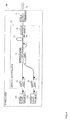
- FIG. 1 is a schematic configuration diagram of an optical multiplexer according to this embodiment.
- An optical multiplexer 10 according to this embodiment is provided with input units 11 and 12, a wavelength multiplexing unit 14, a multiplexed light converting unit 15 and an output unit 16.
- Input ports of the wavelength multiplexing unit 14 are connected to the input units 11 and 12 of the optical multiplexer 10, respectively.
- An output port of the multiplexed light converting unit 15 is connected to the output unit 16 of the optical multiplexer 10.
- Lights of wavelengths ⁇ 1 and ⁇ 2 are input to the input units 11 and 12, respectively.
- the wavelengths ⁇ 1 and ⁇ 2 are different from each other.
- the wavelength multiplexing unit 14 wavelength-multiplexes the lights of a plurality of wavelengths ⁇ 1 and ⁇ 2 input from the input units 11 and 12 different for each wavelength to one multiplexed light. By wavelength-multiplexing, a plurality of input lights may be multiplexed without a loss.
- a wavelength division multiplexer (WDM) may be used as the wavelength multiplexing unit 14.
- the multiplexed light from the wavelength multiplexing unit 14 is input to the multiplexed light converting unit 15.
- the multiplexed light converting unit 15 converts the multiplexed light of the wavelengths ⁇ 1 and ⁇ 2 from the wavelength multiplexing unit 14 to light of a single wavelength ⁇ m .
- the multiplexed light converting unit 15 is a fiber, which generates Raman light by the light of at least one wavelength out of the wavelengths ⁇ 1 and ⁇ 2 included in the multiplexed light from the wavelength multiplexing unit 14.
- the light of the single wavelength ⁇ m is output from the output unit 16 of the optical multiplexer 10.
- the wavelengths ⁇ 1 and ⁇ 2 are set to 1040 nm, 1090 nm or 1140 nm.
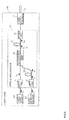
- FIG. 2 is an example of a spectrum of propagating light in each part of the multiplexed light converting unit 15 in which (a) illustrates an input light spectrum to the multiplexed light converting unit and (b) illustrates an output light spectrum from the multiplexed light converting unit. Since each of the light of the wavelength ⁇ 1 and the light of the wavelength ⁇ 2 is converted to the single wavelength ⁇ m , optical intensity of the single wavelength ⁇ m is a value closer to a sum of the optical intensity of the wavelength ⁇ 1 and the optical intensity of the wavelength ⁇ 2 . In this manner, the optical multiplexer 10 illustrated in FIG.
- the 1 may output the light of the single wavelength ⁇ m with large optical intensity by including the wavelength multiplexing unit 14 and the multiplexed light converting unit 15.
- the optical intensity of the single wavelength ⁇ m from the output unit 16 may be further increased.
- the single wavelength ⁇ m is the same wavelength as the longest wavelength ⁇ 2 out of the wavelengths ⁇ 1 and ⁇ 2 included in the multiplexed light from the wavelength multiplexing unit 14.
- the multiplexed light converting unit 15 the light of a short wavelength (wavelength ⁇ 1 ) out of the input two lights of different wavelengths is converted to the other light of the wavelength ⁇ 2 to be output. Since the optical intensity of the light of the wavelength ⁇ 2 is not decreased by the multiplexed light converting unit 15, the optical intensity of the single wavelength ⁇ m may be improved.
- the multiplexed light converting unit 15 transmits the wavelength not shorter than the shortest wavelength ⁇ 1 and not longer than the single wavelength ⁇ m out of the wavelengths ⁇ 1 and ⁇ 2 included in the multiplexed light from the wavelength multiplexing unit 14 and blocks the wavelength longer than the single wavelength ⁇ m .
- the multiplexed light converting unit 15 is the fiber, which continuously causes a loss in a waveguide direction for N-th order Raman light out of the generated Raman light, thereby inhibiting generation of N-th order induced Raman scattering light.
- the multiplexed light converting unit 15 is a PBGF, which causes the loss distributed in the waveguide direction for high-order Raman light, thereby inhibiting generation of high-order induced Raman light. That is to say, it is preferable that a bandgap wavelength band of the PBGF includes the shortest wavelength ⁇ 1 and the single wavelength ⁇ m and does not include a wavelength of a desired order, for example, a secondary Raman light of the shortest wavelength ⁇ 1 . According to this, the continuous loss in the waveguide direction is generated for the desired order (for example, secondary) Raman light and generation of desired order (for example, secondary) Raman scattering light may be inhibited. Further, by winding the PBGF into a coil pattern, the bandgap wavelength band may be finely adjusted.
- the order of the induced Raman light to be inhibited is optional.
- the single wavelength ⁇ m is set to the same wavelength as the wavelength ⁇ 2 and as the wavelength of primary Raman scattering of the wavelength ⁇ 1
- the wavelength of the secondary Raman light of the wavelength ⁇ 1 is inhibited.
- the single wavelength ⁇ m is set to the same wavelength as the wavelength of secondary Raman scattering of the wavelength ⁇ 1 and when the wavelength ⁇ 2 is set to the same wavelength as the wavelength of the primary Raman scattering of the wavelength ⁇ 1
- the wavelength of tertiary Raman light of the wavelength ⁇ 1 is inhibited.
- the order of the induced Raman light to be inhibited is preferably equal or larger than the number of the ports of the input unit.
- the PBGF 500 may optionally set a transmission band and a block band by the periodic structure and the like of the high-refractive index areas 502.
- the transmission band is intended to mean the band of the wavelength, which may be propagated by being confined in the low-refractive index area 501.
- the laser light of the wavelength in the transmission band of the optical multiplexer according to this embodiment is allowed to enter, if the wavelength band in which the spontaneous Raman light is generated is within the bandgap wavelength band of the PBGF 500, the wavelength conversion by the induced Raman scattering occurs.
- the PBGF 500 has a structure in which the wavelength of the secondary Raman light of ⁇ 1 is out of the bandgap wavelength band.
- the plurality of laser light sources 101 and 102 supply the lights of the different output wavelengths to the different input units 11 and 12 of the optical multiplexer 10, respectively.
- the laser light source 101 supplies the light of the wavelength ⁇ 1 to the input unit 11.
- the laser light source 102 supplies the light of the wavelength ⁇ 2 different from the wavelength ⁇ 1 to the input unit 12.
- the optical multiplexer 10 converts the lights of a plurality of wavelengths ⁇ 1 and ⁇ 2 input to the input units 11 and 12 to the light of the single wavelength ⁇ m to output from the output unit 16.
- the laser output terminal 17 outputs the light of the single wavelength ⁇ m .
- the optical multiplexer 10 is as described in the first embodiment.
- a specific example of the fiber laser 100 is described.
- An Yb-doped optical fiber laser of which oscillation wavelength ⁇ 1 is 1040 nm and of which output is 50 W is used as the laser light source 101.
- the Yb-doped optical fiber laser of which oscillation wavelength ⁇ 2 is 1090 nm and of which output is 50 W is used as the laser light source 102.
- the wavelength of the laser light source 102 is selected such that there is the oscillation wavelength in the wavelength band in which the Raman light is generated by propagation of the laser light of the laser light source 101 through the fiber being the multiplexed light converting unit 15.
- the multiplexed light converting unit 15 50m of the PBGF having the bandgap with the wavelength not shorter than 1030 nm and not longer than 1100 nm of which mode field diameter is 10 ⁇ m is used.
- the laser light of which wavelength is 1040 nm generates the Raman light in the vicinity of 1090 nm by the Raman scattering when propagating in the PBGF.
- the laser light of 1090 nm since the laser light of 1090 nm is simultaneously allowed to enter the PBGF, the laser light of 1090 nm induces the induced Raman scattering of the laser light of 1040 nm and the laser light of which wavelength is 1040 nm is converted to the laser light of which wavelength is 1090 nm at high efficiency.
- the band in which the Raman light of the laser light of 1090 nm is generated is in the vicinity of 1140 nm, the vicinity of 1140 nm is outside the bandgap wavelength band and the light of this wavelength cannot be guided to the low-refractive index area (reference numeral 501 in FIG. 3 ), so that further conversion of the wavelength does not occur.
- the laser light of which wavelength is 1090 nm as the single wavelength ⁇ m is output from the laser output terminal 17 as illustrated in FIG. 2 .
- the output of the output laser light is 84 W, and it is confirmed that the two laser lights of different wavelengths are multiplexed at the high efficiency to be output as the laser light of the single wavelength.
- the Yb-doped optical fiber lasers are connected to the input units 11 and 12 as the laser light sources 101 and 102 and the Yb-doped optical fiber has a large gain in the wavelength band from the wavelength 1020 nm to the wavelength approximately 1100 nm. Therefore, by extending the bandgap wavelength band of the PBGF used as the multiplexed light converting unit 15 to approximately 1150 nm, the wavelength conversion to the wavelength 1140 nm inhibited in the first embodiment occurs. In this manner, the output from the laser output terminal 17 may be set outside the gain wavelength band of the Yb-doped optical fiber and brake of the laser light sources 101 and 102 may be prevented even when the reflected light enters the laser light sources 101 and 102.
- FIG. 5 is a schematic configuration diagram of a fiber laser according to this embodiment.
- a fiber laser 200 according to this embodiment is provided with three laser light sources 101, 102 and 103, three input units 11, 12 and 13 and two wavelength multiplexing units 14a and 14b.
- the number of the wavelengths included in the multiplexed light input to the multiplexed light converting unit 15 increases from two to three, so that the optical intensity of the multiplexed light input to the multiplexed light converting unit 15 increases. According to this, the optical intensity of the single wavelength ⁇ m output from the output unit 16 may be increased.
- the multiplexed light converting unit 15 converts the multiplexed light of a plurality of wavelengths from the wavelength multiplexing unit 14 to the light of the single wavelength ⁇ m .
- the multiplexed light converting unit 15 converts to the same wavelength 1140 nm as the longest wavelength ⁇ 3 .
- the multiplexed light converting unit 15 converts to the wavelength of the tertiary Raman light 1200 nm as the single wavelength ⁇ m .
- the output unit 16 and the laser output terminal 17 output the light of the single wavelength ⁇ m .
- FIG. 6 is a schematic configuration diagram of a fiber laser according to this embodiment.
- a fiber laser 300 according to this embodiment is provided with optical multiplexers 10a and 10b and has a configuration in which the optical multiplexers 10 described in the first embodiment are multistage connected.
- a plurality of laser light sources 102 and 101 are connected to the input units 11 and 12 of the optical multiplexer 10a and the lights of the wavelengths ⁇ 2 and ⁇ 1 are input, respectively. Then, the light of the same wavelength as the longest wavelength ⁇ 2 is output from the output unit 16 of the optical multiplexer 10a as the single wavelength ⁇ m .
- the wavelength ⁇ 1 is 1040 nm and the wavelength ⁇ 2 is 1090 nm
- the light of the same wavelength 1090 nm as the longest wavelength ⁇ 2 is output from the output unit 16 of the optical multiplexer 10b.
- the optical intensity of the longest wavelength ⁇ 2 may be increased according to the number of the optical multiplexers 10a and 10b, which are multistage connected.
- the optical intensity of the same wavelength as the longest wavelength ⁇ 2 from the output unit 16 may be further increased.
- FIG. 7 is a schematic configuration diagram of a fiber laser according to this embodiment.
- the laser light source 102 described in the second embodiment is provided with a light generating unit 111 and an output light converting unit 112.
- the laser light sources of different wavelengths are multiplexed in the second to fourth embodiments. Since the wavelength multiplexing is used, the laser lights of the same wavelength cannot be multiplexed. However, by allowing at least one laser light source 102 out of a plurality of laser light sources 101 and 102 to include the light generating unit 111 and the output light converting unit 112, the output light wavelength of the laser light source 101 and the output light wavelength of the light generating unit 111 may be made the same. That is to say, even when the laser light source 101 and the light generating unit 111 have the same configuration, the single wavelength light with high intensity may be obtained by the wavelength multiplexing.
- the laser light source which oscillates at the wavelength ⁇ 1 , is used as the laser light source 101 and the light generating unit 111.
- the laser light of the wavelength ⁇ 1 input from the input unit 11 is directly input to the wavelength multiplexing unit 14.
- FIG. 8 is a schematic configuration diagram of a fiber laser according to a sixth embodiment.
- the laser lights of the wavelengths ⁇ 1 and ⁇ 2 different from each other are input to the input ports of the wavelength multiplexing unit 14. Therefore, it is possible to multiplex without a loss by the wavelength multiplexing unit 14.
- the light multiplexed by the wavelength multiplexing unit 14 is output from the output unit 16 as the light of the wavelength ⁇ m after a process similar to that of the first embodiment.
- An output of the output laser light is 82 W, and it has been confirmed that two fiber laser outputs of the same wavelength are multiplexed to be output as the laser light of a single wavelength component at efficiency substantially equivalent to that of the second embodiment.
- the multiplexed light converting unit 15 is not limited to the PBGF as long as it is configured to transmit the wavelength of the converted light and to generate the continuous loss in the waveguide direction for the Raman light of the desired order.
- the fiber wound into the coil pattern to generate a bending loss from the desired wavelength may be used as the multiplexed light converting unit 15.
- the fiber including dopant to absorb the light of the wavelength band of which generation is desired to be inhibited as the multiplexed light converting unit 15, an effect to generate the continuous loss in the waveguide direction for the Raman light of the desired order may be obtained.
- the present invention may be utilized for a processing fiber laser due to development of a high-output fiber laser, this may be utilized for a broad range of industry such as an electrical equipment industry and a general machinery industry.
Landscapes
- Physics & Mathematics (AREA)
- Electromagnetism (AREA)
- Engineering & Computer Science (AREA)
- Plasma & Fusion (AREA)
- Optics & Photonics (AREA)
- Computer Networks & Wireless Communication (AREA)
- Signal Processing (AREA)
- Optical Modulation, Optical Deflection, Nonlinear Optics, Optical Demodulation, Optical Logic Elements (AREA)
- Lasers (AREA)
Applications Claiming Priority (2)
| Application Number | Priority Date | Filing Date | Title |
|---|---|---|---|
| JP2009012564 | 2009-01-23 | ||
| PCT/JP2010/050185 WO2010084796A1 (fr) | 2009-01-23 | 2010-01-08 | Multiplexeur optique et laser à fibre |
Publications (2)
| Publication Number | Publication Date |
|---|---|
| EP2375281A1 true EP2375281A1 (fr) | 2011-10-12 |
| EP2375281A4 EP2375281A4 (fr) | 2017-08-23 |
Family
ID=42355850
Family Applications (1)
| Application Number | Title | Priority Date | Filing Date |
|---|---|---|---|
| EP10733403.9A Withdrawn EP2375281A4 (fr) | 2009-01-23 | 2010-01-08 | Multiplexeur optique et laser à fibre |
Country Status (6)
| Country | Link |
|---|---|
| US (1) | US9184556B2 (fr) |
| EP (1) | EP2375281A4 (fr) |
| JP (1) | JP5469099B2 (fr) |
| CN (1) | CN102292672B (fr) |
| RU (1) | RU2011135042A (fr) |
| WO (1) | WO2010084796A1 (fr) |
Cited By (1)
| Publication number | Priority date | Publication date | Assignee | Title |
|---|---|---|---|---|
| EP2717095A4 (fr) * | 2011-06-03 | 2015-04-15 | Sumitomo Electric Industries | Dispositif de source de lumière et procédé de traitement |
Families Citing this family (7)
| Publication number | Priority date | Publication date | Assignee | Title |
|---|---|---|---|---|
| CN103091934B (zh) * | 2013-02-05 | 2015-02-11 | 西安邮电大学 | 增益平坦的拉曼光纤波长转换耦合器及方法 |
| WO2015035514A1 (fr) * | 2013-09-12 | 2015-03-19 | Mpb Communications Inc. | Architecture de laser de pompage et système d'étoile guide laser à amplificateur à fibre raman pompé à distance pour télescopes |
| US10408999B2 (en) | 2014-05-09 | 2019-09-10 | National University Corporation University Of Fukui | Multiplexer |
| KR102264191B1 (ko) | 2014-05-09 | 2021-06-10 | 고쿠리츠다이가쿠호징 후쿠이다이가쿠 | 합파기, 이 합파기를 사용한 화상 투영 장치 및 화상 투영 시스템 |
| CN105067146B (zh) * | 2015-03-20 | 2019-09-03 | 深圳市迅捷光通科技有限公司 | 受激拉曼散射抑制装置与方法及分布式光纤传感系统 |
| CN111487713B (zh) * | 2016-02-18 | 2023-01-24 | 日本电信电话株式会社 | 光合波回路 |
| CN108462024B (zh) * | 2018-05-29 | 2023-09-22 | 中国人民解放军国防科技大学 | 一种抑制高亮度窄线宽掺镱光纤放大器中热致模式不稳定的系统 |
Family Cites Families (15)
| Publication number | Priority date | Publication date | Assignee | Title |
|---|---|---|---|---|
| JPH10118038A (ja) | 1996-10-16 | 1998-05-12 | Nippon Colin Co Ltd | 心拍数報知器 |
| JP3808734B2 (ja) * | 2001-08-10 | 2006-08-16 | 富士通株式会社 | ラマン増幅器 |
| JP2003107543A (ja) * | 2001-09-28 | 2003-04-09 | Sumitomo Electric Ind Ltd | ラマン増幅方法、ラマン増幅器、及び光伝送システム |
| US20050024716A1 (en) * | 2003-07-15 | 2005-02-03 | Johan Nilsson | Optical device with immediate gain for brightness enhancement of optical pulses |
| US20050078714A1 (en) * | 2003-10-08 | 2005-04-14 | Hiroshi Komine | High power fiber laser with eye safe wavelengths |
| US7034992B2 (en) * | 2003-10-08 | 2006-04-25 | Northrop Grumman Corporation | Brightness enhancement of diode light sources |
| US7286574B2 (en) * | 2003-11-19 | 2007-10-23 | Neumann Information Systems, Inc. | Infrared laser |
| CN100373252C (zh) * | 2004-05-20 | 2008-03-05 | 北京大学 | 分布式拉曼放大器 |
| US7233442B1 (en) | 2005-01-26 | 2007-06-19 | Aculight Corporation | Method and apparatus for spectral-beam combining of high-power fiber lasers |
| US7420994B2 (en) * | 2005-03-04 | 2008-09-02 | Corning Incorporated | Pulsed cascaded Raman laser |
| US7336869B2 (en) * | 2006-04-14 | 2008-02-26 | Xtera Communications, Inc. | System and method for implementing a high capacity unrepeatered optical communication system |
| WO2007127356A2 (fr) * | 2006-04-28 | 2007-11-08 | Corning Incorporated | Systèmes pulsés de laser raman dans l'ultraviolet et la lumière visible |
| JP2008078728A (ja) * | 2006-09-19 | 2008-04-03 | Fujitsu Ltd | 光伝送装置 |
| US7346085B1 (en) | 2006-10-05 | 2008-03-18 | Northrop Grumman Corporation | Multi-stage method and system for coherent diffractive beam combining |
| RU2460186C2 (ru) | 2007-06-27 | 2012-08-27 | Фудзикура Лтд. | Волоконный лазер, имеющий превосходную стойкость к отраженному свету |
-
2010
- 2010-01-08 RU RU2011135042/28A patent/RU2011135042A/ru unknown
- 2010-01-08 EP EP10733403.9A patent/EP2375281A4/fr not_active Withdrawn
- 2010-01-08 JP JP2010547458A patent/JP5469099B2/ja not_active Expired - Fee Related
- 2010-01-08 WO PCT/JP2010/050185 patent/WO2010084796A1/fr not_active Ceased
- 2010-01-08 US US13/144,745 patent/US9184556B2/en not_active Expired - Fee Related
- 2010-01-08 CN CN201080005205.9A patent/CN102292672B/zh not_active Expired - Fee Related
Non-Patent Citations (1)
| Title |
|---|
| See references of WO2010084796A1 * |
Cited By (1)
| Publication number | Priority date | Publication date | Assignee | Title |
|---|---|---|---|---|
| EP2717095A4 (fr) * | 2011-06-03 | 2015-04-15 | Sumitomo Electric Industries | Dispositif de source de lumière et procédé de traitement |
Also Published As
| Publication number | Publication date |
|---|---|
| US9184556B2 (en) | 2015-11-10 |
| RU2011135042A (ru) | 2013-02-27 |
| JPWO2010084796A1 (ja) | 2012-07-19 |
| JP5469099B2 (ja) | 2014-04-09 |
| CN102292672B (zh) | 2016-06-22 |
| EP2375281A4 (fr) | 2017-08-23 |
| CN102292672A (zh) | 2011-12-21 |
| WO2010084796A1 (fr) | 2010-07-29 |
| US20110274125A1 (en) | 2011-11-10 |
Similar Documents
| Publication | Publication Date | Title |
|---|---|---|
| US9184556B2 (en) | Optical multiplexer and fiber laser | |
| US10625373B2 (en) | Optical arrangements for processing a workpiece | |
| EP3058628B1 (fr) | Procédé et appareil pour produire une lumière laser à puissance élevée | |
| JP6348861B2 (ja) | 光伝送装置及び光伝送方法 | |
| JP2014170850A (ja) | マルチモード伝送用光増幅器 | |
| JP7809691B2 (ja) | レーザ装置および加工装置 | |
| JP6482126B2 (ja) | 光増幅器 | |
| JP5659341B2 (ja) | マルチコア光伝送システム、光増幅及び光増幅用部品 | |
| US7738751B1 (en) | All-fiber laser coupler with high stability | |
| JP5946196B2 (ja) | ファイバおよびファイバ増幅器 | |
| KR20140068795A (ko) | 광대역 광원 | |
| CN110663146B (zh) | 大功率包层泵浦单模光纤拉曼激光器 | |
| JPWO2020071262A1 (ja) | 光増幅装置および光増幅方法 | |
| Uematsu et al. | PLC-type LP 11 mode rotator with single-trench waveguide for mode-division multiplexing transmission | |
| JP5751008B2 (ja) | 光合分波器および光合分波方法 | |
| EP2717095A1 (fr) | Dispositif de source de lumière et procédé de traitement | |
| US6973240B2 (en) | Optical filter | |
| JP2012204372A (ja) | 短パルス光源およびレーザ走査顕微鏡システム | |
| CN114744472A (zh) | 一种支持多种横向模式同时输出的多波长光纤激光器 | |
| US20130315537A1 (en) | Optical multiplexing/demultiplexing device | |
| Wang et al. | Theoretical and experimental optimization of O-band multiwavelength mixed-cascaded phosphosilicate Raman fiber lasers | |
| Chen et al. | Wavelength selective mode conversion in few-mode fiber with cascaded long-period gratings | |
| Jollivet et al. | Advances in multi-core fiber lasers | |
| Arora | Frequency Comb-Based Seed Sources for High-Power Spectral Beam Combining | |
| Zhao et al. | Simulations of multiwavelength cladding pumping of high-power fiber Raman amplifiers |
Legal Events
| Date | Code | Title | Description |
|---|---|---|---|
| PUAI | Public reference made under article 153(3) epc to a published international application that has entered the european phase |
Free format text: ORIGINAL CODE: 0009012 |
|
| 17P | Request for examination filed |
Effective date: 20110628 |
|
| AK | Designated contracting states |
Kind code of ref document: A1 Designated state(s): AT BE BG CH CY CZ DE DK EE ES FI FR GB GR HR HU IE IS IT LI LT LU LV MC MK MT NL NO PL PT RO SE SI SK SM TR |
|
| DAX | Request for extension of the european patent (deleted) | ||
| RA4 | Supplementary search report drawn up and despatched (corrected) |
Effective date: 20170721 |
|
| RIC1 | Information provided on ipc code assigned before grant |
Ipc: H01S 3/30 20060101ALI20170717BHEP Ipc: H01S 3/10 20060101ALI20170717BHEP Ipc: H04B 10/291 20130101ALI20170717BHEP Ipc: H01S 3/067 20060101ALI20170717BHEP Ipc: H01S 3/06 20060101ALI20170717BHEP Ipc: H01S 3/16 20060101ALN20170717BHEP Ipc: H01S 3/094 20060101ALI20170717BHEP Ipc: G02F 1/365 20060101ALI20170717BHEP Ipc: G02F 1/35 20060101AFI20170717BHEP |
|
| STAA | Information on the status of an ep patent application or granted ep patent |
Free format text: STATUS: EXAMINATION IS IN PROGRESS |
|
| 17Q | First examination report despatched |
Effective date: 20191216 |
|
| STAA | Information on the status of an ep patent application or granted ep patent |
Free format text: STATUS: THE APPLICATION HAS BEEN WITHDRAWN |
|
| 18W | Application withdrawn |
Effective date: 20200207 |