EP2375302A2 - Fahrendes Fahrzeugsystem und Selbstdiagnoseverfahren für das fahrende Fahrzeugsystem - Google Patents
Fahrendes Fahrzeugsystem und Selbstdiagnoseverfahren für das fahrende Fahrzeugsystem Download PDFInfo
- Publication number
- EP2375302A2 EP2375302A2 EP11160789A EP11160789A EP2375302A2 EP 2375302 A2 EP2375302 A2 EP 2375302A2 EP 11160789 A EP11160789 A EP 11160789A EP 11160789 A EP11160789 A EP 11160789A EP 2375302 A2 EP2375302 A2 EP 2375302A2
- Authority
- EP
- European Patent Office
- Prior art keywords
- detection
- traveling
- abnormal condition
- traveling vehicle
- positions
- Prior art date
- Legal status (The legal status is an assumption and is not a legal conclusion. Google has not performed a legal analysis and makes no representation as to the accuracy of the status listed.)
- Granted
Links
Images




Classifications
-
- G—PHYSICS
- G05—CONTROLLING; REGULATING
- G05D—SYSTEMS FOR CONTROLLING OR REGULATING NON-ELECTRIC VARIABLES
- G05D1/00—Control of position, course, altitude or attitude of land, water, air or space vehicles, e.g. using automatic pilots
- G05D1/02—Control of position or course in two dimensions
- G05D1/021—Control of position or course in two dimensions specially adapted to land vehicles
- G05D1/0212—Control of position or course in two dimensions specially adapted to land vehicles with means for defining a desired trajectory
-
- G—PHYSICS
- G01—MEASURING; TESTING
- G01M—TESTING STATIC OR DYNAMIC BALANCE OF MACHINES OR STRUCTURES; TESTING OF STRUCTURES OR APPARATUS, NOT OTHERWISE PROVIDED FOR
- G01M17/00—Testing of vehicles
- G01M17/08—Railway vehicles
-
- B—PERFORMING OPERATIONS; TRANSPORTING
- B61—RAILWAYS
- B61L—GUIDING RAILWAY TRAFFIC; ENSURING THE SAFETY OF RAILWAY TRAFFIC
- B61L27/00—Central railway traffic control systems; Trackside control; Communication systems specially adapted therefor
- B61L27/50—Trackside diagnosis or maintenance, e.g. software upgrades
- B61L27/57—Trackside diagnosis or maintenance, e.g. software upgrades for vehicles or trains, e.g. trackside supervision of train conditions
-
- G—PHYSICS
- G05—CONTROLLING; REGULATING
- G05D—SYSTEMS FOR CONTROLLING OR REGULATING NON-ELECTRIC VARIABLES
- G05D1/00—Control of position, course, altitude or attitude of land, water, air or space vehicles, e.g. using automatic pilots
- G05D1/40—Control within particular dimensions
- G05D1/43—Control of position or course in two dimensions [2D]
-
- G—PHYSICS
- G06—COMPUTING OR CALCULATING; COUNTING
- G06F—ELECTRIC DIGITAL DATA PROCESSING
- G06F7/00—Methods or arrangements for processing data by operating upon the order or content of the data handled
-
- H—ELECTRICITY
- H10—SEMICONDUCTOR DEVICES; ELECTRIC SOLID-STATE DEVICES NOT OTHERWISE PROVIDED FOR
- H10P—GENERIC PROCESSES OR APPARATUS FOR THE MANUFACTURE OR TREATMENT OF DEVICES COVERED BY CLASS H10
- H10P72/00—Handling or holding of wafers, substrates or devices during manufacture or treatment thereof
- H10P72/06—Apparatus for monitoring, sorting, marking, testing or measuring
- H10P72/0616—Monitoring of warpages, curvatures, damages, defects or the like
-
- H—ELECTRICITY
- H10—SEMICONDUCTOR DEVICES; ELECTRIC SOLID-STATE DEVICES NOT OTHERWISE PROVIDED FOR
- H10P—GENERIC PROCESSES OR APPARATUS FOR THE MANUFACTURE OR TREATMENT OF DEVICES COVERED BY CLASS H10
- H10P72/00—Handling or holding of wafers, substrates or devices during manufacture or treatment thereof
- H10P72/06—Apparatus for monitoring, sorting, marking, testing or measuring
- H10P72/0618—Apparatus for monitoring, sorting, marking, testing or measuring using identification means, e.g. labels on substrates or labels on containers
-
- H—ELECTRICITY
- H10—SEMICONDUCTOR DEVICES; ELECTRIC SOLID-STATE DEVICES NOT OTHERWISE PROVIDED FOR
- H10P—GENERIC PROCESSES OR APPARATUS FOR THE MANUFACTURE OR TREATMENT OF DEVICES COVERED BY CLASS H10
- H10P72/00—Handling or holding of wafers, substrates or devices during manufacture or treatment thereof
- H10P72/30—Handling or holding of wafers, substrates or devices during manufacture or treatment thereof for conveying, e.g. between different workstations
- H10P72/32—Handling or holding of wafers, substrates or devices during manufacture or treatment thereof for conveying, e.g. between different workstations between different workstations
- H10P72/3214—Handling or holding of wafers, substrates or devices during manufacture or treatment thereof for conveying, e.g. between different workstations between different workstations by means of a cart or a vehicle
-
- H—ELECTRICITY
- H10—SEMICONDUCTOR DEVICES; ELECTRIC SOLID-STATE DEVICES NOT OTHERWISE PROVIDED FOR
- H10P—GENERIC PROCESSES OR APPARATUS FOR THE MANUFACTURE OR TREATMENT OF DEVICES COVERED BY CLASS H10
- H10P72/00—Handling or holding of wafers, substrates or devices during manufacture or treatment thereof
- H10P72/30—Handling or holding of wafers, substrates or devices during manufacture or treatment thereof for conveying, e.g. between different workstations
- H10P72/32—Handling or holding of wafers, substrates or devices during manufacture or treatment thereof for conveying, e.g. between different workstations between different workstations
- H10P72/3221—Overhead conveying
Definitions
- the present invention relates to self-diagnosis of a traveling vehicle system.
- Systems for transporting articles such as FOUPs using traveling vehicles such as overhead traveling vehicles are used in semiconductor factories or the like.
- it is required to maintain the high utilization ratio of the entire system.
- it is required to not only simply transport articles but also provide preventive maintenance for the traveling vehicles of the system and equipment on the ground such as travel rails.
- equipment provided on the ground such as travel rails, equipment associated with the travel rails such as non-contact power feeder line, load ports, buffers as temporal storages of the articles are referred to as the "infrastructure" of the traveling vehicle system.
- An object of the present invention is to perform self-diagnosis of a traveling vehicle system more properly to prevent occurrence of troubles.
- the present invention relates to a traveling vehicle system including a travel route and a plurality of traveling vehicles traveling along the travel route.
- Each of the traveling vehicles is equipped with an abnormal condition detection sensor for reporting an abnormal condition to a ground controller when the abnormal condition is detected.
- the ground controller includes a designation unit configured to provide instructions for the traveling vehicles of positions for performing detection with the abnormal condition detection sensors in the traveling vehicles based on an absolute coordinates for uniquely identifying the positions on the travel route.
- the traveling vehicles include reporting units configured to detect the abnormal condition at the designated positions with the abnormal condition detection sensors and report detection data including the detection positions and detection times to the ground controller.
- the present invention relates to a self-diagnosis method for a traveling vehicle system including a travel route and a plurality of traveling vehicles traveling along the travel route.
- Each of the traveling vehicles is equipped with an abnormal condition detection sensor for reporting an abnormal condition to a ground controller when the abnormal condition is detected.
- the method includes the steps of providing an instruction from the ground controller to the traveling vehicles of positions designated for performing detection with the abnormal condition detection sensors based on absolute coordinates for uniquely identifying positions on the travel route, and performing detection at the designated positions with the abnormal condition detection sensors in the traveling vehicles, and reporting detection data including the detection positions and detection times to the ground controller.
- description regarding the traveling vehicle system is directly applicable to the self-diagnosis method for the traveling vehicle system, conversely, and description regarding the self-diagnosis method for the traveling vehicle system is directly applicable to description regarding the traveling vehicle system.
- the position for performing detection can be designated finely, conditions of the traveling vehicle and the travel route can be detected accurately. Therefore, maintenance for the traveling vehicle or the travel route can be performed before any trouble occurs actually, and preventive maintenance is performed.
- the ground controller is configured to provide instructions for the traveling vehicles of target positions in each predetermined control cycle, and designate positions for performing detection during communication of instructing the target positions.
- the traveling vehicles are configured to carry out velocity control in each control cycle to arrive at the target positions, and perform detection at the designated positions.
- communication does not become complicated.
- bad influences may be caused by the troubles in the traveling vehicle and the troubles on the travel route. Therefore, by providing preventive maintenance for the system, the high throughput of the system can be maintained.
- a storage unit configured to store the detection data from the sensor is provided in the ground controller.
- the detection data is associated with at least velocities and accelerations of the traveling vehicles. Since the meaning of the detection data depends on the velocity and acceleration of the traveling vehicle, by associating the sensor data with these items of data, and storing the sensor data, accurate analysis is achieved.
- the traveling vehicles have abnormal condition detection sensors for detecting an abnormal condition related to traveling and abnormal condition detection sensors for detecting an abnormal condition related to transfer.
- the ground controller is configured to designate a joint between travel rails on the travel route, a diverging point, and a merging point, and a curve segment as positions for performing detection with the abnormal condition detection sensors for detecting the abnormal condition related to traveling, and designate positions for transferring articles between a transfer apparatus of the traveling vehicle and transfer equipment as positions for performing detection with the abnormal condition detection sensors for detecting the abnormal condition related to transfer.
- the condition can be detected by finely designating the position for performing detection.
- the condition of a step or the like that is present at the joint between the travel rails can be detected correctly.
- the ground controller has an identification unit configured to identify positions requiring maintenance on the travel route and traveling vehicles requiring maintenance based on the detection data from a plurality of traveling vehicles at the same position or the detection data from the same traveling vehicle at a plurality of positions.
- an identification unit configured to identify positions requiring maintenance on the travel route and traveling vehicles requiring maintenance based on the detection data from a plurality of traveling vehicles at the same position or the detection data from the same traveling vehicle at a plurality of positions.
- the ground controller includes a time series analysis unit for performing time series analysis of the detection data.
- a time series analysis unit for performing time series analysis of the detection data.
- the traveling vehicles include vibration sensors and sound volume sensors as the abnormal condition detection sensors, and a frequency analyzing unit for performing frequency analysis of data from the vibration sensors and data from the sound volume sensors is provided in the traveling vehicle or the ground controller.
- a frequency analyzing unit for performing frequency analysis of data from the vibration sensors and data from the sound volume sensors is provided in the traveling vehicle or the ground controller.
- the frequency analysis it becomes possible to detect the cause of vibrations, e.g., detect whether the vibrations are caused by the travel motor, the gap in the travel route, loosening in the joint portion between the travel motor and the travel wheels, abrasion or the like.
- the frequency analysis of the sound volume sensor the above determination can be made more reliably based on the frequency of noises.
- the ground controller has a traveling vehicle analysis unit for analyzing a condition of the traveling vehicles based on the detection data from the abnormal condition detection sensors and an infrastructure analysis unit for analyzing a condition on the travel route based on the detection data from the abnormal condition detection sensors.
- Each of the traveling vehicle analysis unit and the infrastructure analysis unit includes an instantaneous value analysis unit for analyzing the abnormal condition based on an instantaneous value of the detection data, and a time series analysis unit for performing time series analysis of the detection data, and a group analysis unit for analyzing the detection data of all of the traveling vehicles or the detection data of the entire travel route.
- FIGS. 1 to 9 show a traveling vehicle system 2 according to the embodiment.
- a reference numeral 4 denotes inter-bay route
- reference numerals 6 denote intra-bay routes
- reference numerals 8 denote maintenance routes.
- the maintenance routes 8 are partially used as parking routes 9.
- Reference numerals 10 denote traveling vehicles. Though overhead traveling vehicles are adopted in the embodiment, the traveling vehicles 10 are not limited to the overhead traveling vehicles, and other types of traveling vehicles may be used as well.
- the maintenance routes 8 may not be dedicated routes. Parts of inter-bay routes 6 may be used as the maintenance routes 8.
- the routes 4 to 9 make up a travel route of the overhead traveling vehicles 10.
- a large number of load ports 12 are provided along the intra-bay routes 6 for transfer of FOUPs between the load ports 12 and semiconductor processing equipment (not shown).
- a large number of buffers 14 are provided along the intra-bay routes 6 and the inter-bay route 4 for temporarily storing the FOUPs in the buffers 14.
- the travel route includes diverging points 16, merging points 18, and curve segments 20.
- the traveling vehicles 10 tend to be vibrated in these portions.
- the travel route is formed by connecting a plurality of travel rails, and the traveling vehicles 10 tend to be vibrated at joints between the travel rails.
- FIG. 1 only some of the load ports 12, the buffers 14, the diverging points 16, the merging points 18, and curve segments 20 are shown.
- the maintenance route 8 is a route used for maintenance of the traveling vehicle 10, and used as a waiting space.
- a reference numeral 22 denotes a lifter for elevating and lowering the traveling vehicles 10 between the ground and the travel rails. Maintenance operation is performed in a working area 24 provided on the ground. Further, when the traveling vehicle 10 travels in the maintenance route 8, for example, vibrations at the time of traveling, occurrence of noises, and electrical current consumed in each motor, accuracy in the travel stop position and the transfer position or the like are detected.
- the data for detection of abnormal conditions is collected over the entire areas of the intra-bay routes 6 and the inter-bay route 4.
- data for detection of abnormal conditions of the traveling vehicle 10 can be collected based on traveling, transfer or the like of the traveling vehicle 10.
- the maintenance routes 8 may not be provided.
- the system controller 30 controls the overall operation of the overhead traveling vehicle system 2.
- a plurality of zone controllers 32 are connected to the ground LAN 34.
- a zone is allocated to each of the zone controllers 32.
- the zone controller 32 communicates with traveling vehicles 10 in its zone for controlling the traveling vehicles 10.
- the zone controller 32 may not be provided.
- the system controller 30 may directly communicate with the traveling vehicles 10 for directly controlling the entire area of the traveling vehicle system 2.
- FIG. 3 shows structure of the traveling vehicle 10 and communication with the zone controller 32.
- the system controller 30 directly communicates with the traveling vehicle 10.
- the traveling vehicle 10 is equipped with a communication unit 40 for communicating its own position and velocity, acceleration, the presence or absence of articles currently being transported, and sensor data obtained from various sensors in each predetermined control cycle.
- the zone controller 32 receives a positioning instruction regarding a target position in the next control cycle, items to be detected by sensors, instructions regarding transfer or the like in each predetermined control cycle.
- the control cycle is 0.1 second, preferably, in a range of 0.01 to 1 second.
- One report or one instruction may be sent by one packet or a plurality of packets.
- the instructions regarding detection are provided during the same communication as the instructions regarding the position or the like. Further, the communication cycle between the zone controller 32 and the traveling vehicle 10 is about 0.1 second, and the clock of the traveling vehicle 10 is synchronized with the clock notified from the zone controller 32. Therefore, reporting from the overhead traveling vehicle 10 may include, or may not include the time data.
- a travel drive unit 45 implements control of a travel motor (not shown). Specifically, the travel drive unit 45 controls the travel motor by generating velocity instructions for allowing the traveling vehicle to reach the target position in the next control cycle designated by the zone controller 32.
- a lateral feed unit 46 laterally feeds an elevation drive unit 48 and a ⁇ drive unit 47 for transfer of articles to or transfer of articles from the buffer or the load port.
- the ⁇ drive unit 47 rotates the elevation drive unit 48 about a vertical axis, e.g., for adjusting the orientation of the FOUPs.
- the elevation drive unit 48 has a hoisting mechanism or the like, for elevating and lowering an elevation frame supporting the FOUPs for transfer of the FOUPs to or from the buffer or the load port.
- Each of the drive units 45 to 48 has at least one motor, and the electrical current value of each motor is detected by an electrical current sensor 56.
- a power receiving unit 50 receive electrical energy from a non-contact power feeder line provided inside the travel rails, and a linear sensor 52 detects marks such as magnets provided along the travel rails for detecting positions based on the marks.
- a height sensor 53 detects a height position of the elevation frame. Specifically, the height sensor 53 detects the height position based on, e.g., the number of rotations of the elevation motor of the elevation derive unit 48.
- a vibration sensor 54 is attached to the elevation frame to detect vibrations applied to articles during transportation of the articles.
- a sound volume sensor 55 detects the volume of sounds generated in the traveling vehicle 10.
- One sound volume sensor 55 may be provided for all of components including the travel drive unit 45. Alternatively, the sound volume sensor 55 5 may be provided for each of the units.
- the electrical current sensor 56 detects electrical current energy consumed in the motor of each drive unit.
- An on board controller 41 implements the overall control of the traveling vehicle 10.
- Data regarding the travel route is written in a map 42.
- absolute coordinates of marks are written in the map 42.
- the absolute coordinate is a coordinate that can uniquely identify a position of the travel route.
- the absolute coordinate include data indicating which route corresponds to the current position and a relative coordinate relative to a reference position in the route.
- a memory 43 stores various items of data generated in the traveling vehicle 10.
- the memory 43 stores data from sensors for detecting abnormal conditions together with the time when the data is generated, the position, velocity, and acceleration of the traveling vehicle, the presence or absence of articles, information regarding the condition such as "in the middle of transfer", “stopped”, and "in the middle of traveling”.
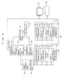
- FIG. 4 shows structure of the system controller 30.
- a reference numeral 60 denotes a communication unit for communication with the zone controller 32. The communication unit communicates with a host controller (not shown), and reports transportation results when there was a request for transportation of articles such as FOUPs.
- a reference numeral 61 denotes an instruction generator unit, and a reference numeral 63 denotes a designation unit for combining instructions from the units 61, 63. Instructions from the units 61, 63 are combined, and provided from the communication unit 60 to the traveling vehicle through the zone controller 32.
- the instruction generator unit 61 generates instructions regarding a target position in the next control cycle, a diverging direction, execution of stop and transfer, and other instructions regarding traveling and transfer.
- the designation unit 63 generates instructions designating detection positions and items that should be detected.
- the detection positions are displayed using the absolute coordinates.
- a memory 62 stores items of data such as the position, time, velocity, acceleration, and the condition of the traveling vehicle, and sensor data. Data for each of the traveling vehicles is obtained in each control cycle through the communication unit 60. Based on these items of data, instructions regarding traveling and transfer are generated by the instruction generator unit 61, and instructions regarding detection are generated by the designation unit 63.
- Two types of instructions are combined by the communication unit 60, and the combined instructions are notified to the traveling vehicle.
- instructions are received in each control cycle and executed in the next control cycle, and the designated detection is performed.
- the current position of the traveling vehicle is stored in the memory 62, and the instruction generator unit 61 designates a target position in the next control cycle. Therefore, at the time of passing the detection position in the next control cycle, detection is instructed. It is sufficient to carry out detection when a detection position and detection items are designated, and it is not necessary to carry out detection in each control cycle.
- the traveling vehicle performs detection at the designated position.
- data for diagnosis determined by the vibration sensor, the sound volume sensor, and the electrical current sensor are stored in the memory 65.
- These items of data in the memory 65 are associated with the ID of the traveling vehicle, the detection time, the detection position, velocity and acceleration at the time of detection, data indicating whether any articles are present or not.
- the detection data may be stored temporarily in the memory of the traveling vehicle, and a plurality of items of data may be communicated collectively to the system controller.
- a preprocessing unit 66 is an FFT (Fast Fourier Transform) unit or the like, and Fourier Transform is applied to data related to frequency such as vibration data and/or sound volume data. Fourier Transform may be performed by the traveling vehicle, and data after Fourier Transform may be notified to the system controller. Diagnosis data is analyzed by a traveling vehicle analysis unit 68 for each of the traveling vehicles. An infrastructure analysis unit 70 analyzes the diagnosis data for equipment on the rail side such as the travel rail, the load port, or the buffer. Though the target of analysis by the analysis units 68, 70 changes depending on the traveling vehicle or the equipment on the ground, the method of analysis does not change.
- FFT Fast Fourier Transform
- An instantaneous value analysis unit 72 analyses instantaneous values of vibration data, the sound volume data, the electrical current data or the like, and classifies the instantaneous values into three types, e.g., a normal range, a caution required range, and an abnormal range.
- a normal range e.g., a caution required range, and an abnormal range.
- the caution required range is present on both of outer sides of the normal range at the center.
- the abnormal range is present on both of outer sides of the caution required range.
- the thresholds of the normal, caution required, and abnormal ranges may vary depending on factors such as the velocity and acceleration of the traveling vehicle, the presence or absence of articles, and the type of detection position.
- the thresholds of the normal, caution required, and abnormal ranges vary depending on whether the traveling vehicle is at the joint between travel rails, whether the traveling vehicle is traveling at a diverging point, the merging point or not, whether the detection position is in a curve segment or not.
- the thresholds of the normal, caution required, and abnormal ranges vary depending on transfer to or from to the load port, transfer to or from the buffer, elevation velocity and elevation acceleration of the elevation frame, lateral feeing amount or the like.
- the instantaneous value analysis unit 72 For example, if the instantaneous value analysis unit 72 detects any abnormal condition, the instantaneous value analysis unit 72 requests the traveling vehicle to retry detection at the next joint between rails. Likewise, the instantaneous value analysis unit 72 requests another traveling vehicle to retry detection at the joint between the rails where the abnormal condition was detected. In this manner, whether the cause of the abnormal condition is present in the traveling vehicle or in the rails or the like is determined.
- a time series analysis unit 73 predicts the future condition of the traveling vehicle and infrastructure based on time series data such as the vibration, sound volume, electrical current or the like of a plurality of traveling vehicles at the same position or the same traveling vehicle at a plurality of positions, and determines whether the future condition is ranked the normal condition, the caution required condition, or the abnormal condition. It is not essential to perform the prediction of the future condition for both of the traveling vehicle and infrastructure. Depending on the situation, the prediction of the condition of one of the traveling vehicle and infrastructure may be omitted. If the predicted condition is determined as any of the ranks of normal, caution required, and abnormal conditions, the thresholds may be changed depending on the velocity and acceleration of the traveling vehicle, and the presence or absence of articles.
- the time series analysis for example, using the time as a variable, for example, the average value and variance or the like of the detection data are determined, and these items of data are extrapolated to the future for determining prediction values. Otherwise, among these items of such distributed data, data close to the abnormal side is extrapolated into the future to determine prediction values. Further, the amount of changes in the data detected each time, i.e., the amount of change in the data between the previous detection and the present detection is determined. Based on the magnitude of the change amount, it is determined whether the condition of the rail, the condition of the traveling vehicle or the like is stable or not. If there is a chance of reaching an abnormal value within one day or within one week, the traveling vehicle is controlled to travel to the maintenance route for performing maintenance operation for the traveling vehicle. In the case where the abnormal condition is caused by equipment such as the travel rail or the buffer, use of the equipment in the abnormal condition is prohibited, and an instruction to perform maintenance operation for the equipment is provided.
- the abnormal condition is caused by equipment such as the travel rail or the buffer, use of the equipment
- a group analysis unit 74 analyses the condition of equipment on the ground such as the condition of a group of traveling vehicles or the condition of a group of travel rails. For example, the average value, dispersion, and the tendencies in the change of the data such as vibrations, noises, and motor's electrical current are determined for all of the traveling vehicles. Further, the average value, dispersion, and the tendencies in change of the data such as vibrations, noises or the like are determined in each position of the equipment on the ground such as the rails. In this manner, the condition of vehicles as a whole and the condition of the travel route as a whole are determined.
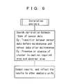
- the correlation analysis unit 75 checks the condition of the traveling vehicle or the condition of the member on the travel route before and after an event such as the maintenance to determine how the condition of the traveling vehicle or the condition of the member on the travel route has been changed by the maintenance, and detects correlation between various items of data.
- the results obtained by the analysis units 72 to 75 are outputted to components such as a monitor 78 and a printer 80, and outputted to the instruction generator unit 61, e.g., as an instruction to travel to the maintenance route.
- the group analysis unit 74 and the correlation analysis unit 75 may not be provided.
- FIG. 5 shows preprocessing of analysis data.
- Fast Fourier transform is applied to vibration data and sound volume data to generate frequency data. Based on the frequency characteristics of the vibration data or the sound volume data, the abnormal position or the cause of the abnormal condition is identified.
- wavelet transform may be performed to develop the frequency characteristics of the vibration data, the time when signals of the vibration data and the sound volume data are generated, and the spatial transition of the signals as a result of movement of the traveling vehicle to more reliably identify the abnormal position. Further, the position where detection was performed, the time when detection was performed, the ID of the traveling vehicle, various items of sensor data, velocity, acceleration, and the electrical current value are inputted to the analysis units as diagnosis data.
- FIG. 6 shows contents of instantaneous value analysis.
- Sensor data is compared with thresholds in correspondence with the condition of the traveling vehicle to classify the condition into any of the normal condition, caution required condition, abnormal condition or the like.
- it is determined whether maintenance is required or not, and items that require maintenance are extracted. If maintenance is required, the details of the abnormal condition, sensor data, and items that require maintenance are outputted. In this manner, since what kind of abnormal condition is present and what kind of maintenance is required can be determined, maintenance can be performed easily.
- vibration data, sound volume data, and the average value and variance of the electrical current value of each motor, and tendencies of the changes in these items of data are determined.
- the traveling vehicle and the position of on the travel route that are deviated from the average value are extracted.
- correlation between items of sensor data is searched. For example, if maintenance is performed normally, after the maintenance, the sensor data should be stabilized. Therefore, it is checked whether the sensor data has been stabilized actually. Assuming that each of factors such as vibrations, noises, velocity, electrical current value or the like is represented by an individual dimension, sensor data obtained one time can be regarded as one point in multi-dimensional space. Cluster is an area as a collection of these points. If there is a cluster in a caution required range or an abnormal range, it indicates that troubles are caused by combination of various factors. When a result is obtained by the correlation analysis, the result is outputted and reflected to other analysis units.
Landscapes
- Engineering & Computer Science (AREA)
- Physics & Mathematics (AREA)
- General Physics & Mathematics (AREA)
- Theoretical Computer Science (AREA)
- Mechanical Engineering (AREA)
- Health & Medical Sciences (AREA)
- General Health & Medical Sciences (AREA)
- Biomedical Technology (AREA)
- Automation & Control Theory (AREA)
- Aviation & Aerospace Engineering (AREA)
- Remote Sensing (AREA)
- Radar, Positioning & Navigation (AREA)
- General Engineering & Computer Science (AREA)
- Control Of Position, Course, Altitude, Or Attitude Of Moving Bodies (AREA)
- Electric Propulsion And Braking For Vehicles (AREA)
- Platform Screen Doors And Railroad Systems (AREA)
- Container, Conveyance, Adherence, Positioning, Of Wafer (AREA)
- Testing Of Devices, Machine Parts, Or Other Structures Thereof (AREA)
Applications Claiming Priority (1)
| Application Number | Priority Date | Filing Date | Title |
|---|---|---|---|
| JP2010088457A JP5110405B2 (ja) | 2010-04-07 | 2010-04-07 | 走行台車システム |
Publications (3)
| Publication Number | Publication Date |
|---|---|
| EP2375302A2 true EP2375302A2 (de) | 2011-10-12 |
| EP2375302A3 EP2375302A3 (de) | 2012-04-18 |
| EP2375302B1 EP2375302B1 (de) | 2014-07-09 |
Family
ID=44064961
Family Applications (1)
| Application Number | Title | Priority Date | Filing Date |
|---|---|---|---|
| EP11160789.1A Not-in-force EP2375302B1 (de) | 2010-04-07 | 2011-04-01 | Hängebahnlaufwagensystem und Selbstdiagnoseverfahren für das Hängebahnlaufwagensystem |
Country Status (7)
| Country | Link |
|---|---|
| US (1) | US8712600B2 (de) |
| EP (1) | EP2375302B1 (de) |
| JP (1) | JP5110405B2 (de) |
| KR (1) | KR101395073B1 (de) |
| CN (1) | CN102213963B (de) |
| SG (1) | SG175494A1 (de) |
| TW (1) | TWI485539B (de) |
Cited By (3)
| Publication number | Priority date | Publication date | Assignee | Title |
|---|---|---|---|---|
| WO2018050502A1 (de) * | 2016-09-19 | 2018-03-22 | Siemens Aktiengesellschaft | Überwachung von infrastruktureinrichtungen mittels geoclustering |
| EP3540547B1 (de) | 2018-03-13 | 2022-07-20 | Gebhardt Fördertechnik GmbH | Verfahren zur funktionsüberwachung eines automatisierten fördersystems und entsprechendes fördersystem |
| EP4389647A1 (de) * | 2022-12-22 | 2024-06-26 | BEUMER Group GmbH & Co. KG | Hängeförderersystem und verfahren zur überwachung eines hängeförderers |
Families Citing this family (72)
| Publication number | Priority date | Publication date | Assignee | Title |
|---|---|---|---|---|
| JP5110405B2 (ja) * | 2010-04-07 | 2012-12-26 | 村田機械株式会社 | 走行台車システム |
| JP5146855B2 (ja) * | 2010-08-09 | 2013-02-20 | 村田機械株式会社 | 天井走行車システム |
| JP5446055B2 (ja) * | 2012-01-27 | 2014-03-19 | 村田機械株式会社 | 台車システム |
| CN102722169A (zh) * | 2012-07-13 | 2012-10-10 | 昆山工研院工业机器人研究所有限公司 | 基于双车同轨的rgv小车智能控制装置 |
| US9026300B2 (en) | 2012-11-06 | 2015-05-05 | Google Inc. | Methods and systems to aid autonomous vehicles driving through a lane merge |
| JP6136434B2 (ja) * | 2013-03-25 | 2017-05-31 | 村田機械株式会社 | 自律移動式無人搬送車 |
| JP6051993B2 (ja) * | 2013-03-25 | 2016-12-27 | 村田機械株式会社 | 自律移動式無人搬送車、及び、自律移動式無人搬送システム |
| CN104627841A (zh) * | 2013-11-13 | 2015-05-20 | 沈阳新松机器人自动化股份有限公司 | 洁净天车避障控制系统 |
| KR101527686B1 (ko) * | 2014-05-02 | 2015-06-10 | 오학서 | 자동 반송 시스템용 데이터 전송 시스템 |
| WO2016103310A1 (ja) * | 2014-12-26 | 2016-06-30 | 川崎重工業株式会社 | 搬送装置の制御装置 |
| US9472098B2 (en) * | 2015-01-15 | 2016-10-18 | International Business Machines Corporation | Vehicle-based abnormal travel event detecting and reporting |
| JP6657498B2 (ja) * | 2015-04-24 | 2020-03-04 | エスゼット ディージェイアイ テクノロジー カンパニー リミテッドSz Dji Technology Co.,Ltd | モバイルプラットフォームの動作情報を提示する方法、装置、およびコンピュータプログラム |
| JP6332147B2 (ja) * | 2015-05-28 | 2018-05-30 | 株式会社ダイフク | 物品取扱設備 |
| JP6531638B2 (ja) * | 2015-12-09 | 2019-06-19 | 株式会社ダイフク | 物品搬送設備 |
| JP6520797B2 (ja) * | 2016-04-11 | 2019-05-29 | 株式会社ダイフク | 物品搬送設備 |
| TW201839890A (zh) * | 2017-02-13 | 2018-11-01 | 日商東京威力科創股份有限公司 | 搬送裝置﹑搬送方法及記憶媒體 |
| JP6910846B2 (ja) * | 2017-05-22 | 2021-07-28 | 東芝テック株式会社 | リーダー装置、及びセンシングシステム |
| EP3647229B1 (de) * | 2017-06-30 | 2022-09-07 | Murata Machinery, Ltd. | Fördersystem und förderverfahren |
| JP7051045B2 (ja) * | 2017-11-08 | 2022-04-11 | オムロン株式会社 | 移動式マニピュレータ、移動式マニピュレータの制御方法及びプログラム |
| TWI648209B (zh) * | 2017-11-29 | 2019-01-21 | 台灣積體電路製造股份有限公司 | 自動化物料處理方法與系統 |
| US10564632B2 (en) | 2017-11-29 | 2020-02-18 | Taiwan Semiconductor Manufacturing Co., Ltd. | Systems and methods for sensory automated material handing |
| CN112292308B (zh) * | 2018-04-20 | 2023-03-31 | 奔腾瑞马cs有限责任公司 | 输送系统和用于控制该输送系统的方法 |
| JP7139164B2 (ja) * | 2018-06-22 | 2022-09-20 | 本田技研工業株式会社 | 共用車管理システム |
| JP7305258B2 (ja) | 2018-07-18 | 2023-07-10 | 株式会社ディスコ | 搬送システム |
| US10479356B1 (en) | 2018-08-17 | 2019-11-19 | Lyft, Inc. | Road segment similarity determination |
| US11348817B2 (en) * | 2018-11-29 | 2022-05-31 | Taiwan Semiconductor Manufacturing Co., Ltd. | Wafer transport system and method for transporting wafers |
| CN113557487B (zh) * | 2019-03-22 | 2024-05-17 | 村田机械株式会社 | 输送车系统 |
| CN111863681B (zh) * | 2019-04-26 | 2024-05-24 | 台湾积体电路制造股份有限公司 | 搬运装置及其应用的搬运系统及搬运系统的预测保养方法 |
| JP7238589B2 (ja) * | 2019-05-13 | 2023-03-14 | トヨタ車体株式会社 | 搬送車管理装置及び搬送車管理方法 |
| US11819965B2 (en) * | 2019-05-17 | 2023-11-21 | Taiwan Semiconductor Manufacturing Company Limited | Device maintenance in semiconductor manufacturing environment |
| US11928557B2 (en) | 2019-06-13 | 2024-03-12 | Lyft, Inc. | Systems and methods for routing vehicles to capture and evaluate targeted scenarios |
| US11637860B2 (en) | 2019-06-17 | 2023-04-25 | At&T Intellectual Property I, L.P. | Autonomous vehicle DoS resistant communication system using acoustic communications |
| US11449475B2 (en) | 2019-06-28 | 2022-09-20 | Lyft, Inc. | Approaches for encoding environmental information |
| US10625748B1 (en) | 2019-06-28 | 2020-04-21 | Lyft, Inc. | Approaches for encoding environmental information |
| US11157007B2 (en) * | 2019-06-28 | 2021-10-26 | Lyft, Inc. | Approaches for encoding environmental information |
| KR102225635B1 (ko) * | 2019-07-19 | 2021-03-12 | 세메스 주식회사 | 대상물 이송 시스템 |
| JP7276468B2 (ja) * | 2019-08-29 | 2023-05-18 | 村田機械株式会社 | 走行車システム |
| IT201900017447A1 (it) | 2019-09-27 | 2021-03-27 | Ocm S P A | Sistema di trasporto e modalità di funzionamento dello stesso |
| US11788846B2 (en) | 2019-09-30 | 2023-10-17 | Lyft, Inc. | Mapping and determining scenarios for geographic regions |
| US11816900B2 (en) | 2019-10-23 | 2023-11-14 | Lyft, Inc. | Approaches for encoding environmental information |
| US12039785B2 (en) | 2019-10-23 | 2024-07-16 | Lyft, Inc. | Approaches for encoding environmental information |
| JP7276164B2 (ja) * | 2020-01-08 | 2023-05-18 | 株式会社ダイフク | 仕分け設備 |
| KR102313087B1 (ko) * | 2020-01-14 | 2021-10-18 | 세메스 주식회사 | Oht 주행 시스템 및 oht 주행 시스템에서의 오차 보정 방법 |
| JP7272290B2 (ja) * | 2020-01-24 | 2023-05-12 | 株式会社ダイフク | 仕分け設備及び走行台車の状態検査方法 |
| US11367637B2 (en) * | 2020-02-11 | 2022-06-21 | Taiwan Semiconductor Manufacturing Co., Ltd. | Method of operating transport system |
| JP7318589B2 (ja) * | 2020-05-25 | 2023-08-01 | 株式会社ダイフク | 物品搬送設備 |
| KR102534402B1 (ko) * | 2020-08-19 | 2023-05-18 | 세메스 주식회사 | 비히클 검사 장치 및 이를 갖는 대상물 이송 시스템 |
| WO2022049929A1 (ja) * | 2020-09-02 | 2022-03-10 | 村田機械株式会社 | 搬送車システム、及び搬送車制御方法 |
| KR102437519B1 (ko) * | 2020-09-02 | 2022-08-29 | 주식회사 에스에프에이 | 포켓 소팅 시스템 |
| JP7334748B2 (ja) * | 2021-01-13 | 2023-08-29 | 株式会社ダイフク | 物品搬送設備 |
| KR102635821B1 (ko) | 2021-02-15 | 2024-02-08 | 삼성전자주식회사 | 기판 이송 장치 및 기판 이송 방법 |
| US12286306B2 (en) * | 2021-03-12 | 2025-04-29 | Taiwan Semiconductor Manufacturing Co., Ltd. | Overhead transport system |
| JP7380637B2 (ja) | 2021-04-13 | 2023-11-15 | 村田機械株式会社 | 有軌道台車 |
| US11798295B2 (en) * | 2021-04-27 | 2023-10-24 | GM Global Technology Operations LLC | Model free lane tracking system |
| KR102896656B1 (ko) * | 2021-09-02 | 2025-12-08 | 세메스 주식회사 | 반송 유닛 및 반송 유닛의 제어 방법 |
| KR102869538B1 (ko) * | 2021-10-20 | 2025-10-13 | 삼성전자주식회사 | 진동 모니터링 시스템 및 모니터링 방법 |
| KR102899702B1 (ko) * | 2021-10-22 | 2025-12-12 | 세메스 주식회사 | 주행 대차의 동작 패턴에 대한 진단 방법 및 주행 대차의 동작 패턴에 대한 진단 장치 |
| KR102899703B1 (ko) * | 2021-11-03 | 2025-12-12 | 세메스 주식회사 | 물품 이송 유닛의 처리 장치 및 물품 이송 유닛의 처리 방법 |
| WO2023084940A1 (ja) * | 2021-11-11 | 2023-05-19 | 村田機械株式会社 | 天井搬送車 |
| KR102925088B1 (ko) * | 2021-12-31 | 2026-02-09 | 세메스 주식회사 | 멀티 테스트용 이송기 |
| JP7661912B2 (ja) * | 2022-03-10 | 2025-04-15 | 株式会社ダイフク | 搬送制御装置、および搬送制御装置の制御方法 |
| JP7729259B2 (ja) * | 2022-05-17 | 2025-08-26 | 株式会社ダイフク | 診断装置、システム、および診断装置の制御方法 |
| CN114646342B (zh) * | 2022-05-19 | 2022-08-02 | 蘑菇物联技术(深圳)有限公司 | 用于定位异常传感器的方法、设备和介质 |
| JP7556376B2 (ja) * | 2022-05-20 | 2024-09-26 | 株式会社ダイフク | 物品搬送設備 |
| JP7845154B2 (ja) * | 2022-11-25 | 2026-04-14 | 株式会社デンソー | 無線給電を利用したセンサシステム |
| KR102897326B1 (ko) * | 2022-11-30 | 2025-12-08 | 세메스 주식회사 | 이송 대차 시스템의 제어 방법 및 제어 장치 |
| JP7831408B2 (ja) * | 2023-06-07 | 2026-03-17 | 株式会社ダイフク | 振動測定装置 |
| KR102817945B1 (ko) * | 2023-06-14 | 2025-06-10 | 삼척루지 주식회사 | 루지바퀴 마모율 자동검사유닛을 갖는 루지 시스템 |
| CN117022979A (zh) * | 2023-09-01 | 2023-11-10 | 新泰市日进化工科技有限公司 | 用于化工原料贮存仓库的无人化智能搬运系统及方法 |
| JP7831468B2 (ja) * | 2023-12-21 | 2026-03-17 | 株式会社ダイフク | レール設置状態判定システム |
| WO2025164000A1 (ja) * | 2024-02-02 | 2025-08-07 | 村田機械株式会社 | 搬送システム |
| JP2025126720A (ja) * | 2024-02-19 | 2025-08-29 | 株式会社ダイフク | 搬送設備 |
Citations (1)
| Publication number | Priority date | Publication date | Assignee | Title |
|---|---|---|---|---|
| JPH04117625A (ja) | 1990-09-07 | 1992-04-17 | Pioneer Electron Corp | 相変化型記録媒体を用いた情報記録方法 |
Family Cites Families (28)
| Publication number | Priority date | Publication date | Assignee | Title |
|---|---|---|---|---|
| JPS5266396A (en) * | 1975-11-28 | 1977-06-01 | Fujitsu Ten Ltd | Device for inspecting trouble detecting and warning device |
| US4977359A (en) * | 1989-11-24 | 1990-12-11 | Omron Tateisi Electronics Co. | Servo motor system requiring a reduced number of signal transmission lines |
| JP2621552B2 (ja) * | 1990-03-06 | 1997-06-18 | 日産自動車株式会社 | 能動型サスペンション |
| US5420794A (en) * | 1993-06-30 | 1995-05-30 | James; Robert D. | Automated highway system for controlling the operating parameters of a vehicle |
| WO1995005951A1 (de) * | 1993-08-26 | 1995-03-02 | Siemens Aktiengesellschaft | Steuerung für ein kraftfahrzeug |
| US8140358B1 (en) * | 1996-01-29 | 2012-03-20 | Progressive Casualty Insurance Company | Vehicle monitoring system |
| US5745030A (en) * | 1996-05-14 | 1998-04-28 | Aaron; Albert | Automatic occupant sensing anti-carjacking system |
| US6100792A (en) * | 1996-05-20 | 2000-08-08 | Alpine Electronics, Inc. | Car security apparatus and car security system |
| US6028537A (en) * | 1996-06-14 | 2000-02-22 | Prince Corporation | Vehicle communication and remote control system |
| JPH10124145A (ja) * | 1996-10-15 | 1998-05-15 | Nippon Yusoki Co Ltd | 無人搬送車における自己診断の異常表示方法及びその装置 |
| US6285931B1 (en) * | 1998-02-05 | 2001-09-04 | Denso Corporation | Vehicle information communication system and method capable of communicating with external management station |
| WO1999060338A1 (en) * | 1998-05-15 | 1999-11-25 | Hitachi, Ltd. | Data processing apparatus and navigation system for pedestrians using the same |
| CA2416373C (en) * | 2000-07-20 | 2007-07-17 | Viraf S. Kapadia | System and method for transportation vehicle monitoring, feedback and control |
| WO2002025291A2 (en) * | 2000-09-21 | 2002-03-28 | American Calcar Inc. | Technique for operating a vehicle effectively and safely |
| US20030040885A1 (en) * | 2001-08-14 | 2003-02-27 | Schoess Jeffrey N. | Apparatus and method for determining vehicle load weight status |
| KR20050089272A (ko) * | 2004-03-04 | 2005-09-08 | 삼성전자주식회사 | 메모리가 내장된 이동체용 열쇠 및 그를 이용한 이동체제어 방법 |
| US20060155439A1 (en) * | 2005-01-12 | 2006-07-13 | Slawinski John A | System and method for using a vehicle's key to collect vehicle data and diagnose mechanical problems, to store and compare security data to allow only authorized use of vehicles and a method to automatically set vehicle features usng the key |
| JP4117625B2 (ja) * | 2005-05-26 | 2008-07-16 | 村田機械株式会社 | 搬送車システム |
| JP4438095B2 (ja) * | 2005-05-26 | 2010-03-24 | 村田機械株式会社 | 搬送システム |
| JP4388532B2 (ja) * | 2006-07-10 | 2009-12-24 | 東海旅客鉄道株式会社 | 鉄道車両の異常検知装置 |
| JP4189826B2 (ja) * | 2006-12-01 | 2008-12-03 | 村田機械株式会社 | 走行台車と走行台車システム |
| JP4306723B2 (ja) * | 2006-12-15 | 2009-08-05 | 村田機械株式会社 | 搬送台車システム |
| JP5138949B2 (ja) * | 2007-02-07 | 2013-02-06 | 日立オートモティブシステムズ株式会社 | 車載ゲートウェイ装置 |
| JP2008239021A (ja) * | 2007-03-28 | 2008-10-09 | Denso Corp | 車両制御装置及びそのデータ書換システム |
| US20090106036A1 (en) * | 2007-10-22 | 2009-04-23 | Kazuya Tamura | Method and system for making automated appointments |
| KR101246280B1 (ko) * | 2008-09-26 | 2013-03-22 | 무라다기카이가부시끼가이샤 | 반송차 시스템 |
| US8495046B1 (en) * | 2010-03-17 | 2013-07-23 | Google Inc. | Encoding locations and using distances for resources |
| JP5110405B2 (ja) * | 2010-04-07 | 2012-12-26 | 村田機械株式会社 | 走行台車システム |
-
2010
- 2010-04-07 JP JP2010088457A patent/JP5110405B2/ja active Active
-
2011
- 2011-03-04 SG SG2011015658A patent/SG175494A1/en unknown
- 2011-03-21 CN CN201110067620.3A patent/CN102213963B/zh not_active Expired - Fee Related
- 2011-03-28 KR KR1020110027794A patent/KR101395073B1/ko not_active Expired - Fee Related
- 2011-04-01 EP EP11160789.1A patent/EP2375302B1/de not_active Not-in-force
- 2011-04-05 US US13/080,259 patent/US8712600B2/en active Active
- 2011-04-06 TW TW100111750A patent/TWI485539B/zh not_active IP Right Cessation
Patent Citations (1)
| Publication number | Priority date | Publication date | Assignee | Title |
|---|---|---|---|---|
| JPH04117625A (ja) | 1990-09-07 | 1992-04-17 | Pioneer Electron Corp | 相変化型記録媒体を用いた情報記録方法 |
Cited By (5)
| Publication number | Priority date | Publication date | Assignee | Title |
|---|---|---|---|---|
| WO2018050502A1 (de) * | 2016-09-19 | 2018-03-22 | Siemens Aktiengesellschaft | Überwachung von infrastruktureinrichtungen mittels geoclustering |
| RU2722370C1 (ru) * | 2016-09-19 | 2020-05-29 | Сименс Мобилити Гмбх | Мониторинг элементов инфраструктуры посредством гео-кластеризации |
| US11299185B2 (en) | 2016-09-19 | 2022-04-12 | Siemens Mobility GmbH | Monitoring infrastructure facilities by means of geo-clustering |
| EP3540547B1 (de) | 2018-03-13 | 2022-07-20 | Gebhardt Fördertechnik GmbH | Verfahren zur funktionsüberwachung eines automatisierten fördersystems und entsprechendes fördersystem |
| EP4389647A1 (de) * | 2022-12-22 | 2024-06-26 | BEUMER Group GmbH & Co. KG | Hängeförderersystem und verfahren zur überwachung eines hängeförderers |
Also Published As
| Publication number | Publication date |
|---|---|
| TW201204619A (en) | 2012-02-01 |
| SG175494A1 (en) | 2011-11-28 |
| JP5110405B2 (ja) | 2012-12-26 |
| JP2011221687A (ja) | 2011-11-04 |
| CN102213963B (zh) | 2014-11-26 |
| CN102213963A (zh) | 2011-10-12 |
| TWI485539B (zh) | 2015-05-21 |
| EP2375302A3 (de) | 2012-04-18 |
| EP2375302B1 (de) | 2014-07-09 |
| KR20110112771A (ko) | 2011-10-13 |
| KR101395073B1 (ko) | 2014-05-14 |
| US20110251735A1 (en) | 2011-10-13 |
| US8712600B2 (en) | 2014-04-29 |
Similar Documents
| Publication | Publication Date | Title |
|---|---|---|
| EP2375302B1 (de) | Hängebahnlaufwagensystem und Selbstdiagnoseverfahren für das Hängebahnlaufwagensystem | |
| US8655518B2 (en) | Transportation network scheduling system and method | |
| EP2620828B1 (de) | Fahrzeugsflotte Managementsystem und Verfahren für die Steuerung der Distanz zwischen Fahrzeuge | |
| US8825367B2 (en) | Vehicle system and method for controlling vehicle system | |
| CN113276911B (zh) | 一种悬挂式单轨车辆段列车位置检测方法及系统 | |
| KR20080055603A (ko) | 반송 대차 시스템 | |
| EP3904991B1 (de) | Fahrzeug und fahrzeugdiagnosesystem | |
| AU2011353672A1 (en) | Data improvement system and method | |
| KR20130001652A (ko) | 무선열차검지유닛을 이용한 열차위치 검지 시스템 | |
| EP2614983A2 (de) | Zugsteuersystem | |
| CN112288353A (zh) | 一种物流运输监控系统 | |
| US8649921B2 (en) | Method and electronic device for monitoring the state of components of railway vehicles | |
| KR20110101951A (ko) | 열차제어시스템 | |
| US20070027615A1 (en) | Guided vehicle system and teaching method in the guided vehicle system | |
| JP2019050691A (ja) | 列車位置検出システム、自動列車制御システム、列車運転支援システム及び列車障害物検知システム | |
| JP2021049813A (ja) | 列車乗車率管理システムおよび列車乗車率管理方法 | |
| KR102044931B1 (ko) | 이송관리시스템의 실시간 위치정보 관리 장치 및 방법 | |
| CN120143746A (zh) | 运送载具和包括该运送载具的运送系统 | |
| JP5398500B2 (ja) | 列車制御装置 | |
| KR102244629B1 (ko) | 도로정비 시스템 | |
| CN118819186A (zh) | 基于gps和gis码头货运路径自动引导系统及方法 | |
| EP3498569B1 (de) | Zugsteuerungssystem | |
| KR102423140B1 (ko) | 차량검지 시스템 및 그의 제어 방법 | |
| TWI868970B (zh) | 軌道車監控管理系統及其軌道車監控管理方法 | |
| JP2004127010A (ja) | 自動搬送装置、自動搬送システム、自動搬送方法および自動搬送プログラム |
Legal Events
| Date | Code | Title | Description |
|---|---|---|---|
| PUAI | Public reference made under article 153(3) epc to a published international application that has entered the european phase |
Free format text: ORIGINAL CODE: 0009012 |
|
| AK | Designated contracting states |
Kind code of ref document: A2 Designated state(s): AL AT BE BG CH CY CZ DE DK EE ES FI FR GB GR HR HU IE IS IT LI LT LU LV MC MK MT NL NO PL PT RO RS SE SI SK SM TR |
|
| AX | Request for extension of the european patent |
Extension state: BA ME |
|
| PUAL | Search report despatched |
Free format text: ORIGINAL CODE: 0009013 |
|
| AK | Designated contracting states |
Kind code of ref document: A3 Designated state(s): AL AT BE BG CH CY CZ DE DK EE ES FI FR GB GR HR HU IE IS IT LI LT LU LV MC MK MT NL NO PL PT RO RS SE SI SK SM TR |
|
| AX | Request for extension of the european patent |
Extension state: BA ME |
|
| RIC1 | Information provided on ipc code assigned before grant |
Ipc: B61B 13/00 20060101ALI20120315BHEP Ipc: G05D 1/02 20060101AFI20120315BHEP |
|
| 17P | Request for examination filed |
Effective date: 20121011 |
|
| GRAP | Despatch of communication of intention to grant a patent |
Free format text: ORIGINAL CODE: EPIDOSNIGR1 |
|
| RIC1 | Information provided on ipc code assigned before grant |
Ipc: B61L 27/00 20060101ALI20140115BHEP Ipc: B61B 13/00 20060101ALI20140115BHEP Ipc: H01L 21/67 20060101ALI20140115BHEP Ipc: G05D 1/02 20060101AFI20140115BHEP Ipc: H01L 21/677 20060101ALI20140115BHEP |
|
| INTG | Intention to grant announced |
Effective date: 20140129 |
|
| RIN1 | Information on inventor provided before grant (corrected) |
Inventor name: HAYASHI, TAKAO |
|
| GRAS | Grant fee paid |
Free format text: ORIGINAL CODE: EPIDOSNIGR3 |
|
| GRAA | (expected) grant |
Free format text: ORIGINAL CODE: 0009210 |
|
| AK | Designated contracting states |
Kind code of ref document: B1 Designated state(s): AL AT BE BG CH CY CZ DE DK EE ES FI FR GB GR HR HU IE IS IT LI LT LU LV MC MK MT NL NO PL PT RO RS SE SI SK SM TR |
|
| REG | Reference to a national code |
Ref country code: GB Ref legal event code: FG4D |
|
| REG | Reference to a national code |
Ref country code: CH Ref legal event code: EP Ref country code: AT Ref legal event code: REF Ref document number: 676789 Country of ref document: AT Kind code of ref document: T Effective date: 20140715 |
|
| REG | Reference to a national code |
Ref country code: IE Ref legal event code: FG4D |
|
| REG | Reference to a national code |
Ref country code: DE Ref legal event code: R096 Ref document number: 602011008221 Country of ref document: DE Effective date: 20140821 |
|
| REG | Reference to a national code |
Ref country code: AT Ref legal event code: MK05 Ref document number: 676789 Country of ref document: AT Kind code of ref document: T Effective date: 20140709 |
|
| REG | Reference to a national code |
Ref country code: NL Ref legal event code: VDEP Effective date: 20140709 |
|
| REG | Reference to a national code |
Ref country code: LT Ref legal event code: MG4D |
|
| PG25 | Lapsed in a contracting state [announced via postgrant information from national office to epo] |
Ref country code: SE Free format text: LAPSE BECAUSE OF FAILURE TO SUBMIT A TRANSLATION OF THE DESCRIPTION OR TO PAY THE FEE WITHIN THE PRESCRIBED TIME-LIMIT Effective date: 20140709 Ref country code: BG Free format text: LAPSE BECAUSE OF FAILURE TO SUBMIT A TRANSLATION OF THE DESCRIPTION OR TO PAY THE FEE WITHIN THE PRESCRIBED TIME-LIMIT Effective date: 20141009 Ref country code: NO Free format text: LAPSE BECAUSE OF FAILURE TO SUBMIT A TRANSLATION OF THE DESCRIPTION OR TO PAY THE FEE WITHIN THE PRESCRIBED TIME-LIMIT Effective date: 20141009 Ref country code: PT Free format text: LAPSE BECAUSE OF FAILURE TO SUBMIT A TRANSLATION OF THE DESCRIPTION OR TO PAY THE FEE WITHIN THE PRESCRIBED TIME-LIMIT Effective date: 20141110 Ref country code: ES Free format text: LAPSE BECAUSE OF FAILURE TO SUBMIT A TRANSLATION OF THE DESCRIPTION OR TO PAY THE FEE WITHIN THE PRESCRIBED TIME-LIMIT Effective date: 20140709 Ref country code: LT Free format text: LAPSE BECAUSE OF FAILURE TO SUBMIT A TRANSLATION OF THE DESCRIPTION OR TO PAY THE FEE WITHIN THE PRESCRIBED TIME-LIMIT Effective date: 20140709 Ref country code: FI Free format text: LAPSE BECAUSE OF FAILURE TO SUBMIT A TRANSLATION OF THE DESCRIPTION OR TO PAY THE FEE WITHIN THE PRESCRIBED TIME-LIMIT Effective date: 20140709 Ref country code: GR Free format text: LAPSE BECAUSE OF FAILURE TO SUBMIT A TRANSLATION OF THE DESCRIPTION OR TO PAY THE FEE WITHIN THE PRESCRIBED TIME-LIMIT Effective date: 20141010 |
|
| PG25 | Lapsed in a contracting state [announced via postgrant information from national office to epo] |
Ref country code: IS Free format text: LAPSE BECAUSE OF FAILURE TO SUBMIT A TRANSLATION OF THE DESCRIPTION OR TO PAY THE FEE WITHIN THE PRESCRIBED TIME-LIMIT Effective date: 20141109 Ref country code: PL Free format text: LAPSE BECAUSE OF FAILURE TO SUBMIT A TRANSLATION OF THE DESCRIPTION OR TO PAY THE FEE WITHIN THE PRESCRIBED TIME-LIMIT Effective date: 20140709 Ref country code: CY Free format text: LAPSE BECAUSE OF FAILURE TO SUBMIT A TRANSLATION OF THE DESCRIPTION OR TO PAY THE FEE WITHIN THE PRESCRIBED TIME-LIMIT Effective date: 20140709 Ref country code: NL Free format text: LAPSE BECAUSE OF FAILURE TO SUBMIT A TRANSLATION OF THE DESCRIPTION OR TO PAY THE FEE WITHIN THE PRESCRIBED TIME-LIMIT Effective date: 20140709 Ref country code: AT Free format text: LAPSE BECAUSE OF FAILURE TO SUBMIT A TRANSLATION OF THE DESCRIPTION OR TO PAY THE FEE WITHIN THE PRESCRIBED TIME-LIMIT Effective date: 20140709 Ref country code: RS Free format text: LAPSE BECAUSE OF FAILURE TO SUBMIT A TRANSLATION OF THE DESCRIPTION OR TO PAY THE FEE WITHIN THE PRESCRIBED TIME-LIMIT Effective date: 20140709 Ref country code: LV Free format text: LAPSE BECAUSE OF FAILURE TO SUBMIT A TRANSLATION OF THE DESCRIPTION OR TO PAY THE FEE WITHIN THE PRESCRIBED TIME-LIMIT Effective date: 20140709 Ref country code: HR Free format text: LAPSE BECAUSE OF FAILURE TO SUBMIT A TRANSLATION OF THE DESCRIPTION OR TO PAY THE FEE WITHIN THE PRESCRIBED TIME-LIMIT Effective date: 20140709 |
|
| REG | Reference to a national code |
Ref country code: DE Ref legal event code: R097 Ref document number: 602011008221 Country of ref document: DE |
|
| REG | Reference to a national code |
Ref country code: FR Ref legal event code: PLFP Year of fee payment: 5 |
|
| PG25 | Lapsed in a contracting state [announced via postgrant information from national office to epo] |
Ref country code: RO Free format text: LAPSE BECAUSE OF FAILURE TO SUBMIT A TRANSLATION OF THE DESCRIPTION OR TO PAY THE FEE WITHIN THE PRESCRIBED TIME-LIMIT Effective date: 20140709 Ref country code: EE Free format text: LAPSE BECAUSE OF FAILURE TO SUBMIT A TRANSLATION OF THE DESCRIPTION OR TO PAY THE FEE WITHIN THE PRESCRIBED TIME-LIMIT Effective date: 20140709 Ref country code: SK Free format text: LAPSE BECAUSE OF FAILURE TO SUBMIT A TRANSLATION OF THE DESCRIPTION OR TO PAY THE FEE WITHIN THE PRESCRIBED TIME-LIMIT Effective date: 20140709 Ref country code: CZ Free format text: LAPSE BECAUSE OF FAILURE TO SUBMIT A TRANSLATION OF THE DESCRIPTION OR TO PAY THE FEE WITHIN THE PRESCRIBED TIME-LIMIT Effective date: 20140709 Ref country code: DK Free format text: LAPSE BECAUSE OF FAILURE TO SUBMIT A TRANSLATION OF THE DESCRIPTION OR TO PAY THE FEE WITHIN THE PRESCRIBED TIME-LIMIT Effective date: 20140709 Ref country code: IT Free format text: LAPSE BECAUSE OF FAILURE TO SUBMIT A TRANSLATION OF THE DESCRIPTION OR TO PAY THE FEE WITHIN THE PRESCRIBED TIME-LIMIT Effective date: 20140709 |
|
| PLBE | No opposition filed within time limit |
Free format text: ORIGINAL CODE: 0009261 |
|
| STAA | Information on the status of an ep patent application or granted ep patent |
Free format text: STATUS: NO OPPOSITION FILED WITHIN TIME LIMIT |
|
| 26N | No opposition filed |
Effective date: 20150410 |
|
| PGFP | Annual fee paid to national office [announced via postgrant information from national office to epo] |
Ref country code: FR Payment date: 20150421 Year of fee payment: 5 |
|
| PG25 | Lapsed in a contracting state [announced via postgrant information from national office to epo] |
Ref country code: LU Free format text: LAPSE BECAUSE OF FAILURE TO SUBMIT A TRANSLATION OF THE DESCRIPTION OR TO PAY THE FEE WITHIN THE PRESCRIBED TIME-LIMIT Effective date: 20150401 Ref country code: MC Free format text: LAPSE BECAUSE OF FAILURE TO SUBMIT A TRANSLATION OF THE DESCRIPTION OR TO PAY THE FEE WITHIN THE PRESCRIBED TIME-LIMIT Effective date: 20140709 Ref country code: SI Free format text: LAPSE BECAUSE OF FAILURE TO SUBMIT A TRANSLATION OF THE DESCRIPTION OR TO PAY THE FEE WITHIN THE PRESCRIBED TIME-LIMIT Effective date: 20140709 |
|
| REG | Reference to a national code |
Ref country code: CH Ref legal event code: PL |
|
| GBPC | Gb: european patent ceased through non-payment of renewal fee |
Effective date: 20150401 |
|
| PG25 | Lapsed in a contracting state [announced via postgrant information from national office to epo] |
Ref country code: LI Free format text: LAPSE BECAUSE OF NON-PAYMENT OF DUE FEES Effective date: 20150430 Ref country code: GB Free format text: LAPSE BECAUSE OF NON-PAYMENT OF DUE FEES Effective date: 20150401 Ref country code: CH Free format text: LAPSE BECAUSE OF NON-PAYMENT OF DUE FEES Effective date: 20150430 |
|
| PG25 | Lapsed in a contracting state [announced via postgrant information from national office to epo] |
Ref country code: BE Free format text: LAPSE BECAUSE OF FAILURE TO SUBMIT A TRANSLATION OF THE DESCRIPTION OR TO PAY THE FEE WITHIN THE PRESCRIBED TIME-LIMIT Effective date: 20140709 |
|
| PG25 | Lapsed in a contracting state [announced via postgrant information from national office to epo] |
Ref country code: MT Free format text: LAPSE BECAUSE OF FAILURE TO SUBMIT A TRANSLATION OF THE DESCRIPTION OR TO PAY THE FEE WITHIN THE PRESCRIBED TIME-LIMIT Effective date: 20140709 |
|
| REG | Reference to a national code |
Ref country code: FR Ref legal event code: ST Effective date: 20161230 |
|
| PG25 | Lapsed in a contracting state [announced via postgrant information from national office to epo] |
Ref country code: FR Free format text: LAPSE BECAUSE OF NON-PAYMENT OF DUE FEES Effective date: 20160502 |
|
| PG25 | Lapsed in a contracting state [announced via postgrant information from national office to epo] |
Ref country code: HU Free format text: LAPSE BECAUSE OF FAILURE TO SUBMIT A TRANSLATION OF THE DESCRIPTION OR TO PAY THE FEE WITHIN THE PRESCRIBED TIME-LIMIT; INVALID AB INITIO Effective date: 20110401 Ref country code: SM Free format text: LAPSE BECAUSE OF FAILURE TO SUBMIT A TRANSLATION OF THE DESCRIPTION OR TO PAY THE FEE WITHIN THE PRESCRIBED TIME-LIMIT Effective date: 20140709 |
|
| PG25 | Lapsed in a contracting state [announced via postgrant information from national office to epo] |
Ref country code: TR Free format text: LAPSE BECAUSE OF FAILURE TO SUBMIT A TRANSLATION OF THE DESCRIPTION OR TO PAY THE FEE WITHIN THE PRESCRIBED TIME-LIMIT Effective date: 20140709 |
|
| PG25 | Lapsed in a contracting state [announced via postgrant information from national office to epo] |
Ref country code: MK Free format text: LAPSE BECAUSE OF FAILURE TO SUBMIT A TRANSLATION OF THE DESCRIPTION OR TO PAY THE FEE WITHIN THE PRESCRIBED TIME-LIMIT Effective date: 20140709 |
|
| PG25 | Lapsed in a contracting state [announced via postgrant information from national office to epo] |
Ref country code: AL Free format text: LAPSE BECAUSE OF FAILURE TO SUBMIT A TRANSLATION OF THE DESCRIPTION OR TO PAY THE FEE WITHIN THE PRESCRIBED TIME-LIMIT Effective date: 20140709 |
|
| PGFP | Annual fee paid to national office [announced via postgrant information from national office to epo] |
Ref country code: IE Payment date: 20220420 Year of fee payment: 12 Ref country code: DE Payment date: 20220420 Year of fee payment: 12 |
|
| REG | Reference to a national code |
Ref country code: DE Ref legal event code: R119 Ref document number: 602011008221 Country of ref document: DE |
|
| REG | Reference to a national code |
Ref country code: DE Ref legal event code: R079 Ref document number: 602011008221 Country of ref document: DE Free format text: PREVIOUS MAIN CLASS: G05D0001020000 Ipc: G05D0001430000 |
|
| PG25 | Lapsed in a contracting state [announced via postgrant information from national office to epo] |
Ref country code: DE Free format text: LAPSE BECAUSE OF NON-PAYMENT OF DUE FEES Effective date: 20231103 |
|
| REG | Reference to a national code |
Ref country code: IE Ref legal event code: MM4A |
|
| PG25 | Lapsed in a contracting state [announced via postgrant information from national office to epo] |
Ref country code: IE Free format text: LAPSE BECAUSE OF NON-PAYMENT OF DUE FEES Effective date: 20230401 |
|
| PG25 | Lapsed in a contracting state [announced via postgrant information from national office to epo] |
Ref country code: IE Free format text: LAPSE BECAUSE OF NON-PAYMENT OF DUE FEES Effective date: 20230401 |