EP2375438A1 - Wolfram-elektrodenmaterial und einrichtung zur messung des emissionsstroms thermischer elektronen - Google Patents
Wolfram-elektrodenmaterial und einrichtung zur messung des emissionsstroms thermischer elektronen Download PDFInfo
- Publication number
- EP2375438A1 EP2375438A1 EP09831885A EP09831885A EP2375438A1 EP 2375438 A1 EP2375438 A1 EP 2375438A1 EP 09831885 A EP09831885 A EP 09831885A EP 09831885 A EP09831885 A EP 09831885A EP 2375438 A1 EP2375438 A1 EP 2375438A1
- Authority
- EP
- European Patent Office
- Prior art keywords
- oxide
- cathode
- tungsten
- thermionic emission
- anode
- Prior art date
- Legal status (The legal status is an assumption and is not a legal conclusion. Google has not performed a legal analysis and makes no representation as to the accuracy of the status listed.)
- Granted
Links
Images










Classifications
-
- H—ELECTRICITY
- H01—ELECTRIC ELEMENTS
- H01J—ELECTRIC DISCHARGE TUBES OR DISCHARGE LAMPS
- H01J1/00—Details of electrodes, of magnetic control means, of screens, or of the mounting or spacing thereof, common to two or more basic types of discharge tubes or lamps
- H01J1/02—Main electrodes
- H01J1/13—Solid thermionic cathodes
- H01J1/14—Solid thermionic cathodes characterised by the material
- H01J1/146—Solid thermionic cathodes characterised by the material with metals or alloys as an emissive material
-
- H—ELECTRICITY
- H01—ELECTRIC ELEMENTS
- H01J—ELECTRIC DISCHARGE TUBES OR DISCHARGE LAMPS
- H01J61/00—Gas-discharge or vapour-discharge lamps
- H01J61/02—Details
- H01J61/04—Electrodes; Screens; Shields
- H01J61/06—Main electrodes
- H01J61/073—Main electrodes for high-pressure discharge lamps
- H01J61/0735—Main electrodes for high-pressure discharge lamps characterised by the material of the electrode
-
- H—ELECTRICITY
- H01—ELECTRIC ELEMENTS
- H01J—ELECTRIC DISCHARGE TUBES OR DISCHARGE LAMPS
- H01J61/00—Gas-discharge or vapour-discharge lamps
- H01J61/02—Details
- H01J61/04—Electrodes; Screens; Shields
- H01J61/06—Main electrodes
- H01J61/073—Main electrodes for high-pressure discharge lamps
- H01J61/0735—Main electrodes for high-pressure discharge lamps characterised by the material of the electrode
- H01J61/0737—Main electrodes for high-pressure discharge lamps characterised by the material of the electrode characterised by the electron emissive material
-
- H—ELECTRICITY
- H01—ELECTRIC ELEMENTS
- H01J—ELECTRIC DISCHARGE TUBES OR DISCHARGE LAMPS
- H01J9/00—Apparatus or processes specially adapted for the manufacture, installation, removal, maintenance of electric discharge tubes, discharge lamps, or parts thereof; Recovery of material from discharge tubes or lamps
- H01J9/42—Measurement or testing during manufacture
-
- H—ELECTRICITY
- H01—ELECTRIC ELEMENTS
- H01B—CABLES; CONDUCTORS; INSULATORS; SELECTION OF MATERIALS FOR THEIR CONDUCTIVE, INSULATING OR DIELECTRIC PROPERTIES
- H01B1/00—Conductors or conductive bodies characterised by the conductive materials; Selection of materials as conductors
- H01B1/06—Conductors or conductive bodies characterised by the conductive materials; Selection of materials as conductors mainly consisting of other non-metallic substances
- H01B1/08—Conductors or conductive bodies characterised by the conductive materials; Selection of materials as conductors mainly consisting of other non-metallic substances oxides
Definitions
- This invention relates to a tungsten electrode material and a thermionic emission current measuring device suitable for evaluating the thermionic emission properties of the tungsten electrode material.
- tungsten electrode hereinafter also referred to as a "tungsten electrode material”, an “electrode material”, or simply an “electrode" which requires the phenomenon of thermionic emission
- thorium oxide is contained in the electrode for use as, for example, the cathode of a discharge lamp or the like with a high heat load for the purpose of improving the thermionic emission properties at a high temperature.
- thorium is a radioactive element and thus, in terms of safety management, there has been proposed a number of techniques that aim to optimize the selection and composition ratio of a thermionic emission substance adapted to replace thorium oxide.
- Patent Document 1 discloses an electron emission material containing W, Ta, Re, or an alloy thereof and, as a thermionic emission substance, a ternary oxide of a Group IIIB metal selected from Sc, Y, and the lanthanides La through Lu and a Group IVB metal selected from Hf, Zr, and Ti, a ternary oxide of a Group IVB metal selected from Hf, Zr, and Ti and a Group IIA metal selected from Be, Mg, Ca, Sr, and Ba, a mixture thereof, or a compound thereof.
- a thermionic emission substance a ternary oxide of a Group IIIB metal selected from Sc, Y, and the lanthanides La through Lu and a Group IVB metal selected from Hf, Zr, and Ti, a ternary oxide of a Group IVB metal selected from Hf, Zr, and Ti and a Group IIA metal selected from Be, Mg, Ca, Sr, and Ba, a mixture thereof, or a compound thereof.
- the electron emission material is produced by blending a high-purity tungsten powder or another refractory alloy powder with an additive powder, consolidating the blended powder into a rod form at a high pressure, sintering the rod to a required density at a high temperature, swaging or forging the rod into a rod form with a higher density and smaller diameter, and then machining the rod to the size of an electrode.
- Patent Document 2 discloses a short-arc high-pressure discharge lamp in which at least a material of a cathode tip portion contains tungsten and, additionally, as a thermionic emission substance, lanthanum oxide La 2 O 3 and at least one kind of another oxide selected from the group of hafnium oxide HfO 2 and zirconium oxide ZrO 2 .
- Patent Document 3 discloses a discharge lamp electrode whose recrystallization temperature is 2000°C or higher, wherein the cathode or anode comprises one or more kinds of tungsten with a purity of 99.95% or more, doped tungsten in which an alkali metal is added at 100ppm or less (excluding 0ppm) to tungsten, and a tungsten-based material in which at least one kind of oxides of cerium, lanthanum, yttrium, strontium, calcium, zirconium, and hafnium is added at 4wt% or less (excluding 0wt%) to tungsten. These oxides are cited as thermionic emission substances.
- This electrode is produced by applying CIP treatment to a powder in which cerium oxide is added to a tungsten powder, to thereby obtain a compact, processing this compact into a shape close to a final shape of the electrode, then sintering the compact in a hydrogen atmosphere at 1800°C, then performing HIP treatment in an argon gas atmosphere at 2000 atm and 1950°C, and then grinding the obtained sintered body.
- Patent Document 4 discloses a high-load and high-intensity discharge lamp, wherein its cathode has a structure in which an oxide of at least one kind of metal selected from lanthanum, cerium, yttrium, scandium, and gadolinium and an oxide of at least one kind of metal selected from titanium, zirconium, hafnium, niobium, and tantalum are coexistent in a high melting point metal base composed mainly of tungsten, and wherein the conversion particle size of the coexisting substance is 15 ⁇ m or greater and the plurality of coexisting substances are present in the high melting point metal base.
- the cathode is produced by the following processes. That is, first, a lanthanum-metal oxide powder having an average particle size of 20 ⁇ m or less and a zirconium-metal oxide powder having the same average particle size of 20 ⁇ m or less are mixed in a ball mill and sintered in the atmosphere at about 1400°C after pressing. Then, the sintered body is again pulverized to obtain an oxide powder in which the lanthanum-metal oxide and the zirconium-metal oxide are coexistent. Then, the obtained oxide powder is classified to obtain a powder having a particle size of 10 to 20 ⁇ m.
- This powder and a tungsten powder having a purity of 99.5wt% or more and an average particle size of 2 to 20 ⁇ m are mixed together, pressed, presintered in hydrogen, and then normally sintered by applying electric current, thereby producing the cathode.
- the method of measurement from electron emission by light is a method of obtaining the work function as average information of the entire emission surface by the phenomenon of photoelectric effect in which electrons are emitted upon irradiation of ultraviolet light or X-ray on the solid surface.
- This measuring method obtains the work function by the photoelectric effect in the atmosphere at ordinary temperature and thus is intended for a semiconductor or an organic compound which is used around the ordinary temperature (Patent Document 5).
- Non-Patent Document 1 the photoelectric effect is given by the following equation (Non-Patent Document 1).
- mv 2 / 2 h v - ⁇
- m is the mass of an electron
- v is the maximum speed of the emitted electron
- ⁇ is the frequency of irradiated light
- ⁇ is the work function.
- the photoelectric effect represents the behavior of a particle having energy of h ⁇ .
- the method of measurement from thermionic emission is a method of measuring a current by thermionic emission (hereinafter referred to as a thermionic emission current) and deriving the work function of a material from a current value thereof.
- a thermionic emission current a current by thermionic emission
- Patent Document 6 a fluorescent lamp is produced and the work function of its cathode is evaluated from the phenomenon of thermionic emission (Patent Document 6).
- the work function serves as a criterion for judging whether or not it is possible to obtain facility of thermionic emission, i.e. excellent properties for a cathode (also called a negative electrode).
- the thermionic emission current density J (A/cm 2 ) of a metal is derived from the following equation (Richardson-Dushman equation).
- J AT 2 ⁇ exp - e ⁇ / kT
- T is the absolute temperature of a thermionic emission substance.
- the thermionic emission current density of pure tungsten is 4.52 ⁇ 10 -5 A/cm 2 at 1773K, which is a practically unmeasurable level, while, it is 0.052A/cm 2 at 2273K, 0.15A/cm 2 at 2373K, and 0.40A/cm 2 at 2473K and thus the thermionic emission current does not reach a measurable level unless the temperature is raised.
- a cathode temperature of about 2200K or higher is required in terms of normal current measurement accuracy.
- Non-Patent Document 2 As a means for obtaining a high temperature so as to obtain a measurable thermionic emission current, there is, for example, a method of carrying out electric heating using a fine line (Non-Patent Document 2).
- Non-Patent Document 1 discloses a work function measurement technique using field emission.
- Patent Document 5 discloses the technique of measuring the work function of the solid surface in the atmosphere at ordinary temperature as described before and, further, its measurement principle is that oxygen in the atmosphere is ionized by photoelectrons and that the resulting oxygen ions are detected. Accordingly, there is a problem that it is not possible to accurately measure the work function at an actual operating temperature of the cathode for use in the discharge lamp.
- the cathode using the substitute material for thorium cannot be accurately evaluated unless the work function of a cathode using a conventional material containing thorium is measured and compared.
- thorium is the radioactive substance as described before and emits ⁇ -rays
- oxygen is ionized by the ⁇ -rays regardless of the emission of photoelectrons and thus the photoelectron emission cannot be accurately measured.
- the work function deriving method based on the photoelectric effect which is described in Patent Document 5 is a technique that is not applicable to the evaluation and comparison of the properties of a cathode material whose operating temperature is high and which contains a radioactive substance and, further, there is a problem that it is not possible to obtain the thermionic emission properties which are important as the properties of a cathode of a discharge lamp, and information of temporal changes thereof.
- the measuring method of Patent Document 6 is a measuring method such that the fluorescent lamp for actual use is produced and that the work function of its cathode is evaluated from the phenomenon of thermionic emission. Since the measurement tends to be affected by various factors, other than the electrode material properties, such as the area of the cathode, the assembling accuracy of the lamp, the shape of an electrode coil, a noble gas as an atmosphere, and the degree of vacuum, it is actually difficult to accurately measure only the electron emission properties of the cathode material by eliminating the influences of these factors.
- Non-Patent Document 2 there have been the following problems in the method of carrying out electric heating using a fine line, of Non-Patent Document 2.
- the work function measurement technique using field emission described in Non-Patent Document 1
- this measurement technique uses the phenomenon of electron emission based on the principle different from that of thermionic emission, there is a drawback that it is not possible to obtain information of the thermionic emission properties which are important as the properties of a cathode for use in a discharge lamp or the like.
- the thorium replacing techniques are insufficient in terms of the prolongation of the electrode life and, further, more than anything else, the techniques themselves for evaluating the thorium replacing techniques are insufficient in terms of the accuracy.
- This invention has been made in view of the above-mentioned points and has a technical object to provide, using a material in place of thorium oxide, a tungsten electrode material that can improve the life of an electrode than conventional, and further to provide a thermionic emission current measuring device which is necessary for accurately grasping the work function of only a cathode, a measuring method thereof, and a work function calculation method.
- the oxide mixture powder is a mixture powder in which different oxides are simply mixed together.
- the present inventors have conducted an additional test using a method of electric current sintering of tungsten which carries out solid-phase sintering just below the melting point while maintaining the shape.
- the present inventors have judged that the reason that an oxide solid solution is not obtained in the above-mentioned prior arts is because the different oxides are in a state of being individually dispersed in the tungsten compact and, therefore, even if, for example, the above-mentioned electric current sintering is carried out, it is difficult for all the oxide particles to cause mass transport so as to take the form of a solid solution.
- the present inventors have made various studies about a method of forming oxides as a solid solution and about a combination of oxides that enables an increase in the melting point.
- the phase of solid solutions C is stable in a wide temperature range particularly in a composition range of M to N in the diagram and the present inventors have considered that it is theoretically possible to obtain a powder of a desired oxide solid solution by selecting the composition in this composition range of the solid solutions C, mixing the respective oxides together, heating the mixture to a temperature of a region of liquid phase L to melt it, uniformly stirring the melt, and then solidifying it.
- oxide particles hereinafter each also referred to as an "oxide solid solution” in which a Zr oxide and/or a Hf oxide and at least one or more kinds of rare earth oxides selected from Sc, Y, and lanthanoids (La, Ce, Pr, Nd, Sm, Eu, Gd, Tb, Dy, Ho, Er, Tm, Yb, and Lu (in this invention, Pm being a radioactive element is excluded (hereinafter referred to as "lanthanoids”)) are solid-dissolved are produced in advance and mixed with a tungsten powder or a mixture powder in which the oxide solid solutions are formed in the tungsten powder is produced in advance and that the mixture powder is pressed and sintered to thereby disperse the oxide solid solutions into the
- a tungsten electrode material characterized by comprising a tungsten base alloy, and oxide particles dispersed in the tungsten base alloy, wherein each oxide particle is an oxide solid solution in which a Zr oxide and/or a Hf oxide and at least one or more kinds of rare earth oxides selected from Sc, Y, La, Ce, Pr, Nd, Sm, Eu, Gd, Tb, Dy, Ho, Er, Tm, Yb, and Lu are solid-dissolved.
- the method of manufacturing the tungsten electrode material according to the first aspect characterized by comprising the steps of producing a hydroxide precipitate from a solution in which a Zr salt and/or a Hf salt and at least one or more kinds of rare earth salts selected from Sc, Y, La, Ce, Pr, Nd, Sm, Eu, Gd, Tb, Dy, Ho, Er, Tm, Yb, and Lu are dissolved in water, drying the hydroxide precipitate to produce a hydroxide powder, heating the hydroxide powder at a temperature of 500°C or more and less than a melting point of the oxide solid solution to produce an oxide solid solution powder, mixing the oxide solid solution powder with a tungsten powder to produce a mixture powder, pressing the mixture powder to produce a compact, sintering the compact in a non-oxidizing atmosphere to produce a sintered body, and plastic working (also called drawing) to the sintered body to produce a tungsten rod material.
- a hydroxide precipitate from a solution in which a
- the method of manufacturing the tungsten electrode material according to the first aspect characterized by comprising the steps of producing a hydroxide precipitate from a solution in which a Zr salt and/or a Hf salt and at least one or more kinds of rare earth salts selected from Sc, Y, La, Ce, Pr, Nd, Sm, Eu, Gd, Tb, Dy, Ho, Er, Tm, Yb, and Lu are dissolved in water, drying the hydroxide precipitate to produce a hydroxide powder, mixing the hydroxide powder with a tungsten oxide to produce a mixture, heating the mixture in a hydrogen atmosphere at a temperature of 500°C or more and less than a melting point of the oxide solid solution to produce a mixture powder in which an oxide solid solution powder is formed in a tungsten powder, pressing the mixture powder to produce a compact, sintering the compact in a non-oxidizing atmosphere to produce a sintered body, and plastic working to the sintered body to produce a
- the method of manufacturing the tungsten electrode material according to the first aspect characterized by comprising the steps of producing a solution in which a Zr salt and/or a Hf salt and at least one or more kinds of rare earth salts selected from Sc, Y, La, Ce, Pr, Nd, Sm, Eu, Gd, Tb, Dy, Ho, Er, Tm, Yb, and Lu are dissolved in water, mixing the mixture solution with a tungsten oxide powder, drying the mixture to produce a dried powder, heating the dried powder in a hydrogen atmosphere at a temperature of 500°C or more and less than a melting point of the oxide solid solution to produce a mixture powder in which an oxide solid solution powder is formed in a tungsten powder, pressing the mixture powder to produce a compact, sintering the compact in a non-oxidizing atmosphere to produce a sintered body, and plastic working to the sintered body to produce a tungsten rod material.
- the present inventors have found that, using electron bombardment heating as a method of heating a cathode, it is possible to obtain a thermionic emission current from the cathode and to accurately calculate the work function of the cathode from this thermionic emission current and specifically that it is possible to evaluate and compare the cathode properties between a cathode material whose operating temperature is high and which contains a radioactive substance such as thorium and a substitute material for thorium.
- a thermionic emission current measuring device characterized by comprising electron bombardment heating means for electron bombardment heating of a cathode, and thermionic emission current measuring means for measuring a thermionic emission current generated by the electron bombardment heating of the cathode by the electron bombardment heating means.
- a thermionic emission current measuring method characterized by comprising (a) electron bombardment heating of a cathode, and (b) measuring a thermionic emission current generated by the electron bombardment heating of the cathode by the electron bombardment heating means.
- a work function calculation method characterized by comprising (d) determining two or more maintaining temperatures of a cathode to carry out electron bombardment heating of the cathode, thereby obtaining thermionic emission currents to derive current densities, (e) linearly approximating the two or more maintaining temperatures to obtain a straight line and deriving a slope and an intercept thereof by extrapolation using the method of least squares, and (f) using an equation 1 which is an equation representing a logarithm of a thermionic emission current density, deriving a work function ⁇ from the slope of the straight line, which is a first term on a ride side of the equation 1:
- ln J / T 2 - e ⁇ / k ⁇ 1 / T + lnA ⁇ : work function (eV), -e: electron charge, k: Boltzmann constant, T: cathode temperature (K), J: thermionic emission current density (A/cm 2 ), A: Richardson constant (A/cm 2 K 2 ).
- thermionic emission current measuring device which is necessary for accurately grasping the work function of only a cathode, a measuring method thereof, and a work function calculation method and, as a consequence, the electrode properties of the material in place of thorium oxide can be evaluated more accurately than conventional.
- the electrode material of this invention comprises a tungsten base alloy and oxide particles dispersed in the tungsten base alloy.
- the oxide particles dispersed in the electrode material of this invention are each an oxide solid solution in which an oxide of Sc, Y, or a lanthanoid excellent in thermionic emission properties and a high melting point Zr oxide and/or Hf oxide are uniformly dissolved.
- the present inventors have confirmed by a test that, as a means for causing the oxide solid solutions to be present in the tungsten electrode material, it is necessary to cause the oxide solid solutions to be present in a tungsten powder before press-forming the tungsten powder, i.e. in advance.
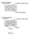
- the electrode material of this invention in which the oxide solid solutions are present represents an electrode material in which, as shown at A in Fig. 2 , one or more kinds of oxide solid solutions (in the case of the same figure, one kind of oxide solid solution) are dispersed at the grain boundaries of tungsten crystal particles or in the tungsten crystal particles in a cross-sectional structure of the electrode material.
- Oxide solid solution represents a state of a solid particle in which two or more kinds of oxides are uniformly dissolved at an arbitrary composition ratio. That is, if this state is compared to liquids, it is not a state (mixture) in which the liquids have no solubility in each other, such as water and oil, and thus are separated into two phases, but is a state (solution) in which the liquids are dissolved in each other to form a homogenous single-phase composition, such as water and ethanol. The latter corresponds to a solid solution in the case of solids.
- the oxide solid solution of this invention represents a state where the oxide of Zr or Hf and the oxide of Sc, Y, or the lanthanoid are uniformly dissolved in a single phase.
- the phase of the solid solution should be stable in the wide temperature range, that is, the oxide should have a high melting point.
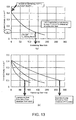
- Non-Patent Document 3 shows a ZrO 2 -Er 2 O 3 binary phase diagram as an example in which the Zr oxide or the Hf oxide and the oxide of Sc, Y, or the lanthanoid are solid-dissolved.
- a region of "Solid Solution C” is a range in which the Zr oxide and the Er oxide are solid-dissolved.
- a region of “Liquid Phase L” is a range in which the Zr oxide and the Er oxide are in the form of a liquid.
- the solid solution C (solid) and the liquid phase L (liquid) coexist and, therefore, upon entering this region, the liquid phase appears and melting starts.
- the melting point of Er 2 O 3 alone is 2370°C.
- a boundary line between the region of "Coexistence of C and L" and the region of "Solid Solution C", i.e. the boundary line where the liquid phase appears shows 2370°C which is equal to the melting point of Er 2 O 3 alone.
- the boundary line rises above the melting point of Er 2 O 3 alone.
- the boundary line is the highest at 2790°C with a composition in which about 20mol% Er 2 O 3 is solid-dissolved. This is the composition with the highest melting point.
- Fig. 1(b) is a ZrO 2 -Sm 2 O 3 binary phase diagram. Like in Fig. 1(a) , a region of "Solid Solution C” is a range in which the Zr oxide and the Sm oxide are in the form of a solid solution and a region of "Liquid Phase L” is a range in which the Zr oxide and the Sm oxide are in the form of a liquid. Upon entering a region of "Coexistence of C and L", melting starts.
- the melting point of Sm 2 O 3 alone is 2330°C.
- a boundary line where the liquid phase appears shows 2330°C which is equal to the melting point of Sm 2 O 3 alone. Then, as mol% of Sm 2 O 3 decreases, the boundary line rises and, when the solid solution approaches a composition of 0mol% Sm 2 O 3 , it shows a maximum of 2710°C.
- the solid solution has a melting point above that of the Sc, Y, or lanthanoid oxide alone and, further, may have a melting point above that of the Zr or Hf oxide alone.
- the melting point of the oxide solid solution exceeds the melting points of the respective combined oxides alone. That is, an increase in the melting point is determined by the combination of the oxides and the composition ratio thereof.
- Non-Patent Document 1 From phase diagrams shown in Non-Patent Document 1, the present inventors have read the melting points of the oxides alone and, in solid solutions in which the Zr oxide and the oxides of Sc, Y, and the lanthanoids are combined, respectively, within the scope of this invention, have read the composition ranges where the melting point of the solid solution becomes higher than that of the Sc, Y, or lanthanoid oxide alone, and the melting point increase upper limits. For each lanthanoid oxide, a chemical formula with the most stable oxidation number is shown. These are collectively shown in Table 1 along with the melting points of the Zr oxide alone and the Hf oxide alone. (In Table 1, the oxides of Sc, Y, and the lanthanoids are shown as rare earth oxides)
- Non-Patent Document 3 in phase diagrams of the Hf oxide and the oxides of Sc, Y, and the lanthanoids, the liquid phase appearing temperatures are equal to or higher than those of the combinations of the Zr oxide and the oxides of Sc, Y, and the lanthanoids, respectively.
- solid solutions of the Hf oxide and the oxides of Sc, Y, and the lanthanoids can also have melting points higher than those of the Sc, Y, and lanthanoid oxides alone, respectively.
- oxide solid solutions each comprising the Zr oxide and/or the Hf oxide and the oxide of one kind selected from La, Sm, Er, Yb, and Y.
- oxide solid solutions other than exemplified, each comprising the Zr oxide and/or the Hf oxide and an oxide of at least one or more kinds selected from Sc, Y, La, Ce, Pr, Nd, Sm, Eu, Gd, Tb, Dy, Ho, Er, Tm, Yb, and Lu can also have high melting points as in the Examples, these oxide solid solutions may also be used.
- the content of the oxide solid solutions in the total amount of the electrode material is preferably 0.5mass% to 5mass% (the balance is substantially tungsten).
- the cross-sectional area of those oxide solid solutions each having a cross-section whose long axis direction forms an angle of 20° or less with the axial direction, be 50% or more of the cross-sectional area of all the oxide solid solutions.
- the directions of the long axes of the oxide solid solutions be aligned with the axial direction.
- the electrode material satisfying such a condition can be obtained by, for example, adjusting the average particle size and the processing ratio (area reduction ratio after the processing) of the oxide solid solutions.
- the processing ratio and the particle size are complementary to each other such that if the particle size is large, the directions are easily aligned even if the processing ratio is low, while, if the processing ratio is high, the directions are easily aligned even if the particle size is small.
- Axial direction referred to herein represents a center axis direction when the electrode material is formed in a columnar shape
- cross-section in an axial direction represents a cross-section when the electrode material is cut so as to be parallel to the center axis and to include the center axis.
- long axis referred to herein represents a major axis of an ellipse equivalent to the cross-sectional shape of the oxide solid solution and, specifically, a major axis of an ellipse having the same area and the same first and second moments as those of the cross-sectional shape of the oxide solid solution. Even when a hole (void) exists in the cross-sectional shape, the cross-sectional area represents an area including the hole.
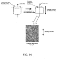
- the structure of the oxide solid solution in the cross-section in the axial direction of the electrode material can be observed by, for example, a general metallurgical microscope or an electron probe microanalyzer (EPMA) that specifies the position and shape of an oxide.
- EPMA electron probe microanalyzer
- the size of the oxide solid solution can be evaluated by binarizing an image, taken by the EPMA, using an image processing software such as, for example, Image Pro Plus manufactured by Media Cybernetics, Inc. and standardizing the area of the oxide solid solution particle as a tungsten area ratio along with the results of quantitative analysis by ICP emission spectral analysis according to JIS H 1403.
- the area ratio of those oxide solid solutions, each having a cross-section with an aspect ratio of 6 or more be 4% or more of the cross-sectional area of all the oxide solid solutions.
- the oxide solid solution for electron emission is gradually supplied in the depth direction so that the exhaustion time of the electrode is improved.
- the electrode material satisfying such a condition can be obtained by, for example, removing those oxide solid solution particles with a particle size of 5 ⁇ m or less and setting the processing ratio to 20% or more.
- the processing ratio and the particle size are complementary to each other such that if the particles are coarse, the particles with the aspect ratio of 6 or more are easily formed even if the processing ratio is low, while, if the processing ratio is high, the particles with the aspect ratio of 6 or more are easily formed even if the particles are fine.
- Aspect ratio referred to herein represents a (major axis/minor axis) ratio of an ellipse equivalent to the cross-sectional shape of the oxide solid solution.
- the meanings of "axial direction”, “cross-section in an axial direction”, and “cross-sectional area” are the same as those described in ⁇ Anisotropy in Shape of Oxide Solid Solutions in Electrode Material of this Invention>.
- the total area of those oxide solid solutions, each having a cross-section with a circle-converted particle size of 5 ⁇ m or less be less than 50% of the area of all the oxide solid solutions.
- particle size represents a diameter when the cross-section of the oxide solid solution is converted into a perfect circle having the same area.
- the meanings of "axial direction”, “cross-section in an axial direction”, and “cross-sectional area” are the same as those described in ⁇ Anisotropy in Shape of Oxide Solid Solutions in Electrode Material of this Invention>.
- the electrode material satisfying such a condition can be obtained by, for example, a method of controlling the size of the oxide solid solution powder through screening and, more specifically, it can be obtained by a method of removing the powder of the oxide solid solutions of 5 ⁇ m or less by screening, a method of, conversely, setting the powder of primary particles (high-frequency particle size on the fine particle size side in a distribution obtained by laser particle size distribution) to 1 ⁇ m or less to thereby increase aggregated particles so as to increase the size of the oxide solid solutions in an electrode as a result, a method of setting the powder of secondary particles to 3 ⁇ m or less to thereby promote sintering of the oxide solid solutions so as to increase the size of the oxide solid solutions in an electrode, or the like.
- the standard deviation of the molar ratios of the rare earth element to all the metal elements in the oxide solid solutions is 0.025 or less.
- the electrode material of this invention contains the oxide solid solutions which show a relationship where, in the elements forming the oxide solid solutions, the standard deviation ⁇ of the ratios of the total moles of Sc, Y, La, Ce, Pr, Nd, Sm, Eu, Gd, Tb, Dy, Ho, Er, Tm, Yb, and Lu to the total moles of the elements in the oxide solid solutions excluding oxygen is ⁇ 0.025.
- the electrode material satisfying such a condition can be obtained by one of the above-mentioned manufacturing methods.
- the existing state of an oxide before being mixed with a tungsten powder is an oxide solid solution of this invention or an oxide (an oxide alone, a mixture of oxides, or an oxide obtained by stoichiometric combination at a predetermined molar ratio) of the above-mentioned prior arts.
- the reason is that the lattice constant, the crystal structure, and so on differ depending on the existing state of the oxide so that unique X-ray diffraction peaks appear according to that existing state.
- An oxide comprising Zr, Yb, and O and obtained by stoichiometrically combining at a predetermined molar ratio, i.e. chemically bonded oxide, represents, for example, Zr 3 Yb 4 O 12 .
- the peaks unique to Zr 3 Yb 4 O 12 are observed as shown in the powder X-ray diffraction file (JCPDS).
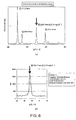
- the peaks of a solid solution of ZrO 2 and Yb 2 O 3 (25mol%) obtained by X-ray diffraction, the peaks of Zr 3 Yb 4 O 12 shown in the JCPDS, and the peaks of a mixture of ZrO 2 alone and Yb 2 O 3 alone (25mol%) obtained by X-ray diffraction are collectively shown in Figs. 3 and 4 .
- the oxide before being mixed with the tungsten powder which is shown in Patent Document 1, i.e. La 2 Zr 2 O 7 or the like, is in a state where the constituent elements are chemically bonded at a predetermined molar ratio.
- the oxide obtained by the method of Patent Document 1 belongs to (2) of later-described classification.
- the pulverized powder was pressed at a pressure of 98MPa to produce a compact.
- the obtained compact was sintered in the atmosphere at 1400°C and then again pulverized to obtain a metal oxide.
- the metal oxide was analyzed by X-ray diffraction.
- La 2 O 3 and ZrO 2 were mainly observed while La 2 Zr 2 O 7 in which the oxides were stoichiometrically combined at the predetermined molar ratio formed only a very small part. That is, it has been found that the mixture in which the La-metal oxide and the Zr-metal oxide were individually present was predominant even after the heating.
- Patent Document 4 the oxide obtained by the method of Patent Document 4 (referred to as a "coexisting substance" in Patent Document 4) belongs to (2) and (3) of the later-described classification while Patent Documents 2 and 3 belong to (3) of the later-described classification like Patent Document 4, that is, any of them is not an oxide solid solution.
- the oxide solid solution, the complex oxide, and the mixture exhibit the different existing states even if the constituent elements and the composition ratio thereof are the same.
- An electrode produced using the oxide shown in each of Patent Documents 1 to 4 has a cross-sectional structure as shown at B in Fig. 2 . That is, it is the technique of using a powder in which an oxide solid solution is not formed and, therefore, when a mixture of oxides is used, there is obtained an electrode material in which two or more kinds of oxides of Zr or Hf and Sc, Y, or a lanthanoid are individually dispersed, while, when a complex oxide/oxides is/are used, there is obtained an electrode material in which one or more kinds of complex oxides of Zr or Hf and Sc, Y, or a lanthanoid are dispersed.
- the same figure shows the case of a mixture of two kinds of oxides or the case of two kinds of complex oxides.
- the manufacturing method of (a) in Fig. 5 uses a tungsten powder while the manufacturing methods of (b) and (c) in Fig. 5 use a tungsten oxide powder.
- the manufacturing method to be used can be selected depending on whether the starting material is the tungsten powder or the tungsten oxide powder.
- the manufacturing method of (a) in Fig. 5 is a method of producing an oxide solid solution in advance and then mixing it, while, each of the manufacturing methods of (b) and (c) in Fig. 5 is a method of mixing a mixture as a precursor of an oxide solid solution with tungsten oxide and then changing the precursor into the oxide solid solution in a later process.
- a hydroxide precipitate of Zr hydroxide and Er hydroxide is first produced using a coprecipitation method.
- the chlorides corresponding to the composition of a desired oxide solid solution are dissolved so that the concentration of the solution is adjusted to 0.5mol/L in the total moles of Zr and Er.
- the solution A is stirred.
- the solution A shows acidity.
- Sodium hydroxide (purity 99mass%) is dissolved in water and the concentration is adjusted to 0.5mol/L (this is given as a solution B).
- the solution B shows alkalinity.
- the solution B continues to be dropped and, when the pH of the solution A exceeds pH7, the neutralization reactions are completed.
- the concentrations and amounts (volumes) of the solutions A and B may be determined so that metal ions in the solution A and OH ions in the solution B are all reacted.
- the precipitate of the hydroxides can be separated using precipitation, filtration, or a centrifugal separator. By appropriately repeating washing and separation to remove excessive OH - ions and other ions contained in the precipitate of the hydroxides, there is obtained a precipitate of the hydroxides (hereinafter referred to as a "hydroxide precipitate").
- an oxide solid solution powder production method can be rationalized such that (1) nitrate, sulfate, or the like is used instead of chloride, (2) a basic solution such as aqueous ammonia is used instead of a sodium hydroxide solution, (3) adjustment is carried out to increase the concentration of a solution, or the like, (4) adjustment is carried out to raise the temperature of a solution in the formation of a precipitate, or the like, or (5) the concentrations and amounts (volumes) of solutions A and B are determined so as to increase the pH at the completion of mixing of the solutions.
- the combination and compositions of components of a solution are required to be the combination and compositions of components of a solid solution according to a phase diagram of an oxide of Zr or Hf and an oxide of Sc, Y, or a lanthanoid, or the like and the preparation thereof can be appropriately changed depending on required thermionic emission properties, economical efficiency, and so on.
- the hydroxide precipitate is heated to thereby produce a powder in a dried state.
- This powder is a powder of Zr and Er hydroxides with moisture slightly remaining. This moisture is preferably completely removed, but is also removed in the next drying/roasting process (heat treatment).
- the hydroxide powder is heat-treated, thereby producing an oxide solid solution powder in which ZrO 2 and Er 2 O 3 are solid-dissolved.
- An atmosphere of the heat treatment is not limited to the atmosphere. It may be an atmosphere of nitrogen, argon, vacuum, or the like as long as the hydroxides can be dehydrated.
- the lower limit of the temperature of the heat treatment is 500°C. This is because if it is below 500°C, the hydroxides remain as they are so that a desired oxide solid solution powder cannot be obtained.
- the upper limit of the temperature is less than the melting point of the oxide solid solution. Further taking into account the aggregation and seizure of the oxide solid solution powder, the adjustment of the particle size of the powder, and the capability and productivity of a furnace, the temperature is preferably 500 to 1500°C.
- the obtained oxide solid solution powder has a purity of 99mass% or more and a particle size of about 1 to 10 ⁇ m.
- the particle size of the oxide solid solution powder is a value measured by a laser diffraction method (the same in other Examples).
- the mixture powder can be produced by a method which is popular as a tungsten manufacturing method, such as mixing using a mixer or a mortar.
- a general tungsten powder having a purity of 99.9mass% (3N) is used.
- a high-purity tungsten powder with less metal impurities it is possible to prevent the melting point depression of the tungsten base alloy and thus to reduce the wear of an electrode.
- the mixture powder is press-formed into a compact (also referred to as a "pressed body") by a method which is popular as a tungsten manufacturing method, such as metal mold pressing or cold isostatic pressing (CIP).
- a tungsten manufacturing method such as metal mold pressing or cold isostatic pressing (CIP).
- the pressing pressure is preferably 98MPa to 588MPa which is generally used. According to need such as obtaining a strength necessary for handling the pressed body, presintering may be suitably carried out.
- the compact is sintered in a non-oxidizing atmosphere to produce a sintered body.
- the compact is sintered at 1750°C or more, thereby obtaining the sintered body having a relative density of 95% or more.
- the sintering temperature is preferably set to 1800°C in consideration of the sintered body productivity and to 2000°C or more in consideration of improving the sintered body density.
- the upper limit of the sintering temperature is set to less than the melting point of tungsten in consideration of maintaining the shape of the compact.
- the sintering method can be sintering by indirect heating or sintering by direct electric heating.
- the sintering temperature is 2400°C or less in the former due to restriction of an apparatus, while, is 3000°C or less in the latter.
- An atmosphere of the sintering can be suitably selected from a general hydrogen gas reducing atmosphere, inert argon atmosphere, and vacuum.
- the sintering temperature and time are not limited to the conditions given in the later-described Examples of this invention, but can be properly set in consideration of a required sintered body density, the processability in the next plastic working, and so on.
- Tungsten Rod Material also called Rod-Shaped Material or Columnar Material
- plastic working is applied to the sintered body so as to generally provide a relative density of 98% or more, thereby producing a tungsten rod material. This is because the mechanical properties or the like are required for an electrode.
- plastic working use can be made of a method which is popular as a tungsten material manufacturing method, such as hot swaging, drawing, or rolling.
- This method is a production method which uses a tungsten oxide powder instead of the tungsten powder used at (a) in Fig. 5 .
- a particular difference from the production method of (a) in Fig. 5 resides in [Process of producing Oxide Solid Solution Powder].
- a hydroxide precipitate of Zr hydroxide and Er hydroxide is produced using the coprecipitation method described in the production method of (a) in Fig. 5 .
- the hydroxide powder obtained above and the tungsten oxide powder are mixed together to produce a mixture.
- the purity of the tungsten oxide is such that the purity of tungsten excluding oxygen is 99.9mass% or more.
- the particle size is preferably 1 to 10 ⁇ m (measured by the Fsss (Fischer) method).
- the mixture can be produced by mixing using a method which is popular as a tungsten manufacturing method, such as a mixer.
- the tungsten oxide powder becomes a tungsten powder and, simultaneously, the powder of Zr and Er hydroxides as a precursor of an oxide solid solution becomes an oxide solid solution powder. In this manner, a mixture powder of the tungsten powder and the oxide solid solution powder is produced.
- the lower limit of the reduction temperature is 500°C. This is because if it is below 500°C, the hydroxides of the hydroxide powder remain as they are so that a desired oxide solid solution powder cannot be obtained, and further, the tungsten oxide is not reduced so that subsequent sintering cannot be carried out.
- the upper limit of the temperature is less than the melting point of the oxide solid solution. Further taking into account the aggregation of the oxide solid solution powder, the adjustment of the particle size of the powder, the seizure of the powder, the reduction of the tungsten oxide, and the capability and productivity of a furnace, the temperature is preferably 800 to 1000°C.
- the reduction of the tungsten powder for a tungsten electrode is generally carried out at 800 to 1000°C so that the precursor produced in this production method of (b) in Fig. 5 or a precursor produced in a later-described process of (c) in Fig. 5 can be completely solid-dissolved in the reduction process.
- tungsten oxide use can be made of tungsten trioxide (WO 3 ), blue oxide (typical composition formula W 4 O 11 ), tungsten dioxide (WO 2 ), or the like.
- This method is, like (b) in Fig. 5 described above, a production method which uses a tungsten oxide powder instead of the tungsten powder of (a) in Fig. 5 .
- a solution in which Zr chloride and Er chloride are dissolved in water at a predetermined ratio is produced as a precursor of an oxide solid solution and then is mixed with a tungsten oxide powder.
- This mixture may be produced by using nitrate, sulfate, or the like instead of chloride, increasing the concentration of the solution, diluting the aqueous solution with ethyl alcohol, or the like.
- the above-mentioned mixing is carried out by a general method using a mixer or the like for use in the manufacture of tungsten.
- the mixture is heated at about 100°C to 250°C, thereby producing a mixed/dried tungsten oxide powder.
- Moisture is preferably completely removed, but is also removed in the next hydrogen reduction process.
- the tungsten oxide powder becomes a tungsten powder and, simultaneously, a powder of an oxide solid solution of ZrO 2 and Er 2 O 3 is formed. In this manner, a mixture powder of the tungsten powder and the oxide solid solution powder is produced.
- the lower limit and the upper limit of the reduction temperature and the tungsten oxide used are the same as those in the production method of (b) in Fig. 5 .
- tungsten is obtained by the reduction in the hydrogen atmosphere, Zr or Er metal alone is not obtained while ZrO 2 and Er 2 O 3 are produced.
- ⁇ G° of the standard free energy of formation of oxidation decreases, the reaction proceeds in a direction that produces an oxide.
- ⁇ G° of the following chemical reaction formulas at 1027°C are as follows, respectively.
- the mixture ratio of the oxide solid solution powder to the tungsten powder can be arbitrarily changed in the electrode material of this invention.
- the oxide solid solution content of the electrode material as a final product can be properly designed.
- the content ranges will be shown in the later-described Comparative Examples.
- tungsten electrode materials as evaluation samples shown in the following Examples 1 to 13, were produced by the method of (a) in Fig. 5 .
- the mass ratio of Zr chloride and La chloride was determined so as to provide 95mol% ZrO 2 and 5mol% La 2 O 3 .
- the Zr chloride and the La chloride were dissolved in water and the concentration was adjusted to 0.2mol/L. While stirring an obtained aqueous solution, 2mol/L aqueous ammonia was dropped into the aqueous solution. The aqueous ammonia was dropped until the aqueous solution reached pH8, thereby obtaining a hydroxide precipitate of Zr and La.
- the hydroxide precipitate was dried at 200°C and then the dried hydroxide precipitate was roasted in the atmosphere at 1000°C, thereby obtaining an oxide solid solution powder.
- This powder was confirmed to be a solid solution powder of ZrO 2 and La 2 O 3 by X-ray diffraction.
- the particle size of the obtained oxide solid solution was about 1 to 10 ⁇ m.
- the above-mentioned ZrO 2 -La 2 O 3 oxide (95mol% ZrO 2 and 5mol% La 2 O 3 were solid-dissolved) powder was mixed with a general tungsten powder having a purity of 99.9mass% or more and an average particle size of about 4 ⁇ m (measured by the Fsss (Fischer) method). Then, the obtained tungsten powder was mold-pressed at 196MPa, thereby obtaining a cylindrical compact with a diameter of 30mm and a height of 20mm. The mixing amount of the ZrO 2 -La 2 O 3 oxide was adjusted so that it would be finally contained at 1.0mass% in a tungsten electrode material.
- a tungsten electrode material was produced in the production sequence of Example 1 except that a ZrO 2 -20mol% Sm 2 O 3 oxide solid solution was used.
- Example 2 An oxide in which ZrO 2 and Er 2 O 3 were solid-dissolved was produced in the production sequence of Example 1. Specifically, a ZrO 2 -Er 2 O 3 oxide solid solution (78mol% ZrO 2 and 22mol% Er 2 O 3 were solid-dissolved) powder was mixed with a general tungsten powder having a purity of 99.9mass% or more and an average particle size of about 4 ⁇ m (measured by the Fsss (Fischer) method).
- the tungsten powder was press-formed, then heated in a hydrogen atmosphere at 1200°C for 1 hour, and then subjected to electric current sintering in a hydrogen atmosphere at 2500°C to 3000°C, thereby producing a rod-shaped tungsten electrode material with a cross-section of 25mm ⁇ 25mm.
- a tungsten electrode material was produced in the production sequence of Example 1 except that a ZrO 2 -22mol% Er 2 O 3 oxide solid solution powder was used.
- a tungsten electrode material was produced in the production sequence of Example 1 except that a ZrO 2 -25mol% Yb 2 O 3 oxide solid solution powder was used.
- a tungsten electrode material was produced in the production sequence of Example 1 except that a ZrO 2 -23mol% Y 2 O 3 oxide solid solution powder was used.
- a tungsten electrode material was produced in the production sequence of Example 1 except that a ZrO 2 , HfO 2 -Er 2 O 3 (22mol% Er 2 O 3 , 39mol% ZrO 2 , 39mol% HfO 2 ) oxide solid solution powder was used.
- a tungsten electrode material was produced in the production sequence of Example 1 except that a HfO 2 -22mol% Er 2 O 3 oxide solid solution powder was used.
- a tungsten electrode material was produced in the production sequence of Example 4 except that the content (mass%) of the ZrO 2 -Er 2 O 3 oxide solid solution powder of Example 3 was set to 0.5%.
- a tungsten electrode material was produced in the production sequence of Example 4 except that the content (mass%) of the ZrO 2 -Er 2 O 3 oxide solid solution powder of Example 3 was set to 5%.
- a tungsten electrode material was produced in the production sequence of Example 1 except that the rare earth oxide composition of the Zr 2 -Er z 0 3 oxide solid solution of Example 3 was changed to ZrO 2 -10mo1% Er 2 O 3 .
- a tungsten electrode material was produced in the production sequence of Example 1 except that the rare earth oxide composition of the ZrO 2 -Er 2 O 3 oxide solid solution of Example 3 was changed to ZrO 2 -40mol% Er 2 O 3 .
- the relative densities of the electrode materials obtained in Examples 2, 3, 5 to 9, 12, and 13 were the same as that in Example 1.
- the relative densities of the electrode materials obtained in Examples 4, 10, and 11 were about 98%.
- tungsten electrode materials as evaluation samples shown in the following Reference Examples 1 to 3 (Comparative Examples 1 to 3), were produced as reference examples and, further, tungsten electrode materials as evaluation samples, shown in the following Comparative Examples 4 to 16, were produced as comparative examples.
- a tungsten electrode material was produced in the production sequence of Example 4 except that the content of the ZrO 2 -Er 2 O 3 oxide solid solution of Example 3 was set to 0.1 mass%.
- a tungsten electrode material was produced in the production sequence of Example 4 except that the content of the ZrO 2 -Er 2 O 3 oxide solid solution of Example 3 was set to 6mass%.
- a tungsten electrode material was produced in the production sequence of Example 4 except that the content of the ZrO 2 -Er 2 O 3 oxide solid solution of Example 3 was set to 10mass%.
- Comparative Examples 4 to 8 oxides were arbitrarily selected from complex oxides shown in Patent Document 1, then, using the production sequence of Example 1, a mixture powder of a powder of each of the selected oxides and a tungsten powder was mold-pressed into a cylindrical compact at 196MPa. Then, since the sintering temperature was not shown in the specification of Patent Document 1, sintering was carried out in a hydrogen gas atmosphere for 10 hours at 1800°C where sintering of tungsten was enabled, thereby producing tungsten electrode materials.
- CaZrO 3 (manufactured by Kojundo Chemical, purity 99mass%) was used as an oxide.
- SrZrO 3 (manufactured by AlfaAeser, purity 99mass%) was used as an oxide.
- BaZrO 3 (manufactured by AlfaAeser, purity 99mass%) was used as an oxide.
- BaHfO 3 (manufactured by Kojundo Chemical, purity 99mass%) was used as an oxide.
- a mixture of ZrO 2 alone and Y 2 O 3 alone (manufactured by Kojundo Chemical, purity 99mass%, 77mol% ZrO 2 and 23mol% Y 2 O 3 ) was used as an oxide.
- ZrO 2 (manufactured by Kojundo Chemical, purity 99mass%) was used as an oxide.
- La 2 O 3 (manufactured by Wako Pure Chemical, purity 99mass%) was used as an oxide.
- Comparative Examples 14 to 16 were produced in the following sequences.
- a tungsten electrode material was obtained in the same production sequence as in Example 3 except that a Zr oxide alone and an Er oxide alone were used as oxides. More specifically, using commercial products as oxides, a powder of the respective commercial ZrO 2 and Er 2 O 3 oxides (manufactured by Wako Pure Chemical, 78mol% ZrO 2 and 22mol% Er 2 O 3 ) each having a purity of 99mass% was mixed with a general tungsten powder having a purity of 99.9mass% or more.
- a tungsten electrode material containing a coexisting substance of a La-metal oxide and a Zr-metal oxide was produced according to Example 1 of Patent Document 4.
- a commercial tungsten electrode material containing ThO 2 -2.0mass% thorium oxide was prepared.
- the oxide solid solution confirmation method described before attention was paid to the highest intensity line among the peaks obtained by the X-ray diffraction.
- the oxide state confirmation was performed paying attention to the peaks different from the highest intensity line.
- Fig. 10(b) The results of X-ray diffraction of Example 3 are shown in Fig. 10(b) .
- the peak of the ZrO 2 -Er 2 O 3 oxide solid solution was measured at 2 ⁇ / ⁇ equal to that of the peak (peak of the oxide solid solution powder) indicated by an arrow of circled number 3 in Fig. 10(a) . That is, it was confirmed that the ZrO 2 -Er 2 O 3 oxide solid solution contained in the sample of Example 3 maintained its solid-dissolved state in the tungsten electrode material without being lost even after the sintering.
- Example 4 Although not illustrated, the same X-ray diffraction results as in Example 3 were obtained in Example 4. Further, it was confirmed that the ZrO 2 -Er 2 O 3 oxide solid solution maintained its solid-dissolved state in the tungsten electrode material without being lost even after the swaging.
- the peaks of tungsten and the peaks of the respective oxide solid solutions were measured as in Examples 1 to 7. That is, the oxide solid solution maintained its solid-dissolved state in the tungsten electrode material without being lost even after the sintering.
- the particle size of the oxide solid solutions contained in the tungsten electrode materials of Examples 1 to 13 was about 1 to 10 ⁇ m and thus was substantially the same as the particle size before the sintering.
- the particle size of the oxide solid solution was measured using a SEM (scanning electron microscope) photograph of the powder and a microscopic photograph of a polished surface of the sintered body.
- the peaks of tungsten and the peaks of the oxide solid solution were measured as in Examples 1 to 13. That is, the oxide solid solution maintained its solid-dissolved state in the tungsten electrode material without being lost even after the sintering.
- Fig. 9(b) the X-ray diffraction results of Comparative Example 9 are shown in Fig. 9(b) .
- the constituent elements (Zr, Y, and O) of the oxide of Comparative Example 9 were the same as those of Example 7.
- the peak (arrow of circled number 1 in Fig. 9(a) ) of the ZrO 2 -Y 2 O 3 oxide solid solution was not observed while the peaks (arrows of circled number 2 in Fig. 9(b) ) of ZrO 2 and Y 2 O 3 were respectively observed. That is, it was confirmed that the oxide mixture of ZrO 2 and Y 2 O 3 did not form a solid solution even if sintered and it was seen that the mixed state was maintained in the tungsten electrode material.
- cylindrical evaluation samples each having a diameter of 8mm and a height of 10mm were produced by applying cutting, polishing, and degreasing to the respective tungsten electrode materials of Examples 1 to 13, Reference Example 1, Comparative Examples 4 to 14, and Comparative Example 16 (commercial product) which were obtained by the above-mentioned methods, and then the thermionic emission was measured using a thermionic emission current measuring device 100 which was created by the present inventors for evaluating a tungsten electrode material of this invention.
- the thermionic emission current measuring device 100 comprises a measuring device body 1 forming an electron bombardment heating means, a DC power supply 2, a pulsed power supply 3, and a current-voltage measuring device 6 (oscilloscope) forming a thermionic emission current measuring means.
- the DC power supply 2 and the pulsed power supply 3 form a power supply device.
- the thermionic emission current measuring device 100 further comprises a temperature measuring portion 5 as a heating temperature measuring means.
- the measuring device body 1 comprises a vacuum chamber 13, a sample stage 17 provided in the vacuum chamber 13 for placing thereon a cathode 15 as a measurement sample, an anode 19 provided in the vacuum chamber 13, and a filament 21 provided in the vacuum chamber 13.
- the filament 21 is connected to a filament power supply 4 having an isolation transformer 23.
- the isolation transformer 23 is for heating the filament 21 and provides isolation between the DC power supply 2 for electron bombardment heating and the filament power supply 4 to prevent direct electrical connection therebetween.
- a current is supplied to the filament 21 so that the filament 21 is heated to emit thermal electrons.
- a voltage is applied to the filament 21 using the DC power supply 2 to accelerate the thermal electrons, thereby applying electron bombardment to the sample serving as the cathode 15 to heat it.
- a pulse voltage is applied to the anode 19 and, using the current-voltage measuring device 6 (oscilloscope), the voltage between ground and the anode 19 and the voltage between ground and the cathode 15 are measured. Simultaneously with this, the amount of thermal electrons reaching the anode 19 from the heated cathode 15, i.e. the current, is also measured using the current-voltage measuring device 6 (oscilloscope).
- the filament 21, which is supplied with AC power from the isolation transformer 23 to be heated is set to a negative potential with respect to ground using the DC power supply 2 for electron bombardment heating. Since the cathode 15 is at the same potential as ground, thermal electrons emitted from the filament 21 proceed to the cathode 15 to effect electron bombardment heating of the cathode 15. As a consequence, the cathode 15 with a defined area can be heated to a predetermined temperature.
- the measuring device body 1 comprises the vacuum chamber 13, the sample stage 17 for placing the cathode 15 thereon, the anode 19, and the filament 21.
- the vacuum chamber 13 can achieve high vacuum.
- the purpose can be accomplished with a general vacuum device.
- a stable vacuum atmosphere required for this invention can be obtained by properly remodeling the inside of a chamber of MUE-ECO manufactured by ULVAC, Inc.
- the pressure inside of the vacuum chamber 13 is required to be 10 -4 Pa or less even during heating for the purpose of electron bombardment heating. This, however, can be realized by combining known baking equipment, a turbomolecular pump or a cryopump, and a rotary pump.
- sample stage 17 be configured to apply electron bombardment heating to the back side of the cathode 15, thereby making it possible to accurately heat a large-area surface of the cathode 15 to a temperature high enough for thermionic emission which is difficult to obtain by electric heating.
- the sample stage 17 it is sufficient for the sample stage 17 to have a structure that can fix the cathode 15 for electrode material evaluation aimed at by this invention.
- the sample stage 17 is preferably formed of, for example, a molybdenum material having heat resistance.
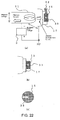
- the structure thereof may be such that, as illustrated in Fig. 22(a) , a circular flat surface portion adapted to receive electron bombardment is formed into an annular shape with a recess and the cathode 15 can be inserted into this recess and fixed by a screw 32 or the like.
- a fixing method may be brazing or use can be made of an arbitrary technique such as electron beam welding.
- the cathode 15 is preferably made of a material composed mainly of a high melting point metal.
- the cathode 15 has a disk shape and has a certain or greater size so that it is possible to reduce its deformation in high-temperature heating and further to measure the thermionic emission current more accurately.
- the outer diameter of the cathode 15 is preferably set to, for example, about ⁇ 8mm. This is because it is possible to obtain a measurement-limit current density and necessary pulse voltage and current.
- a temperature measuring hole 33 is provided from a side wall of the cathode 15 toward its center as shown in Fig. 22(c) . This is because, by providing the temperature measuring hole 33 having a depth of 4 or more with respect to an inlet diameter of 1, the emissivity corresponding to blackbody radiation becomes 1 so that the emission temperature measurement can be carried out with high accuracy.
- the cathode 15 is not limited to a high melting point pure metal. It may be a metal containing an oxide, a carbide, or the like or an alloy containing a plurality of components. Specifically, it may be a material in which the electrical conduction can be confirmed, for example, the resistivity is about 1 ⁇ 10 -6 ⁇ m or less at room temperature.
- the anode 19 is configured to be disposed coaxially with the sample stage 17 for placing the cathode 15 thereon.
- the anode 19 is in the form of a circular solid molybdenum round bar and has a cylindrical guard ring 35, also made of molybdenum, on the circumference of a front end portion of the anode, thereby forming a guard ring added anode.
- the material of the anode and the guard ring 35 is not necessarily limited to molybdenum as long as it is a high melting point metal that does not degrade in a test.
- the anode 19 is disposed in a state of being insulated from the vacuum chamber 13.
- the anode 19 is configured to use the guard ring 35, the accuracy of the diameter allows a plus tolerance, and if the offset of the center axis is within a range where the guard ring 35 is provided (position where the circumference of the guard ring 35 is located in a direction perpendicular to an end portion of the cathode 15), it is possible to carry out a measurement in which the area of the anode 19 is defined, without any problem.
- the guard ring 35 is provided on the circumference of the facing anode 19.
- the anode 19 is free of the influence of the edge effect so that uniform electric field distribution is provided, and therefore, it is possible to measure uniform current density.
- the facing anode 19 and the guard ring 35 are held parallel to the cathode 15 with a distance of 0.5mm therebetween.
- the cross-sectional area of the guard ring 35 is set to be equal to or greater than that of the anode 19.
- the facing anode 19 and the guard ring 35 are disposed coaxially with the cathode 15.
- a thermionic emission surface of the cathode 15 has a diameter of ⁇ 8mm and an electrode cross-section of the anode 19 has a diameter of ⁇ 6.2mm.
- a current due to thermal electrons reaching the electrode cross-section of the anode 19, i.e. the cross-section with the diameter of ⁇ 6.2mm, from the cathode 15 is a thermionic emission current.
- the guard ring 35 is configured to have an outer diameter of ⁇ 9.2mm and an inner diameter of ⁇ 6.6mm with a clearance of 0.2mm from the anode 19 so as not to affect the measurement current.
- each of their cross-sections is preferably circular. This is because, in a shape other than a circle, such as, for example, a square, the edge effect appears more significantly at corners.
- the diameter of the cathode 15 is preferably ⁇ 1mm or more for preventing the edge effect like the anode 19 and is more preferably ⁇ 3mm to ⁇ 20mm in terms of the measurement lower limit of current and the restriction of the heating power supply which will be described later.
- the measurement lower limit of current is about 1mA.
- the upper limit of the diameter of the cathode 15 is restricted by the upper limit of the output of the DC power supply 2 for electron bombardment heating. As the diameter increases, the sample weight increases so that the output required for heating increases. In this invention using the known device, the diameter of 20mm is the upper limit.
- the diameter of the anode 19 preferably satisfies "cathode diameter ⁇ anode diameter + 1mm" in the range of 3 to 19mm.
- the upper limit 19mm of the diameter of the anode 19 may possibly be less than 19mm depending on the thermionic emission current density of the cathode 15 and the measurement upper limit of the measuring device.
- the diameter of the anode 19 is less than 3mm, the current becomes below the measurement lower limit of current and thus is difficult to measure. If it exceeds 19mm, the influence of the edge effect cannot be ignored when the cathode diameter is the maximum of 20mm. In the case of a sample whose thermionic emission current is relatively large, when the diameter of the anode 19 is large, there is a possibility that the current exceeds the measurement upper limit of current to damage the measuring device.
- the inner diameter of the guard ring 35 preferably satisfies "anode diameter + 1mm ⁇ guard ring inner diameter > anode diameter". This is because the inner diameter of the guard ring 35 is preferably as close to the diameter of the anode 19 as possible in order to remove the edge effect of the anode 19, while, if it exceeds the anode diameter + 1 mm, the effect of removing the edge effect is reduced.
- the outer diameter of the guard ring 35 preferably satisfies "guard ring outer diameter ⁇ cathode diameter + 1 mm" and "guard ring cross-sectional area / anode cross-sectional area ⁇ 1". This is because unless these are satisfied, the effect of removing the edge effect is reduced. However, it is necessary that the upper limit of the outer diameter of the guard ring 35 be reconsidered to be smaller depending on the thermionic emission current density of the cathode 15 and the measurement upper limit of the measuring device.
- the distance between the cathode 15 and the anode 19 is preferably in the range of 0.1mm to 1mm. This is because if the distance is large, the electric field strength decreases even at the same pulse voltage so that the actual measurement current decreases to approach the measurement region lower limit.
- the distance between the cathode 15 and the anode 19 becomes less than 0.1 mm, the possibility increases that the cathode 15 and the anode 19 are brought into contact with each other due to thermal expansion of the constituent components and so on. If it exceeds 1 mm, there is a possibility that the current becomes below the measurement lower limit of emission current and thus is unable to be measured.
- the filament 21 serving as an electron source for electron bombardment heating is in the form of a coil of a tungsten line having a diameter of ⁇ 1mm and is disposed on the back side of the sample stage 17.
- DC power supply 2 for electron bombardment to the cathode use can be made of, for example, a DC high-voltage stabilized power supply RR5-120 manufactured by GAMMA.
- An emission current can be accurately read by applying a pulse voltage.
- the pulsed power supply 3 can be a very popular high-pressure pulsed power supply and it is possible to use, for example, YHPG-40K-20ATR of YAMABISHI Corporation, or the like.
- the filament power supply 4 for heating the filament 21 is used by adjusting a supply voltage of 100V to an adequate voltage using Slidac.
- the isolation transformer 23 use can be made of, for example, MNR-GT manufactured by UNION Electronics, Co., Ltd.
- the isolation transformer 23 is for heating the filament 21 and provides isolation between the DC power supply 2 for electron bombardment heating and the filament power supply 4 to prevent direct electrical connection therebetween.
- the temperature measuring portion 5 is used for measuring the temperature of the cathode 15 and a radiation thermometer is suitable for this.
- a monochromatic radiation thermometer with a short measurement wavelength is highly reliable in temperature measurement.
- TR-630 and a close-up lens No. 110 manufactured by Minolta Co., Ltd. it is possible to measure the temperature of a region with a diameter of ⁇ 0.4mm.
- a measurement region at a temperature due to emission or less is measured by disposing a tungsten-rhenium thermocouple on the opposite side of the sample.
- an oscilloscope is used as the current-voltage measuring device 6 in this embodiment.
- DL9710L manufactured by Yokogawa Electric Corporation can be used.
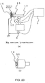
- the measurement system of the cathode 15 and the anode 19 is shown in Fig. 23(a) .
- an electrical circuit shown in the same figure it is possible to read a thermionic emission current received by the anode 19, potential differences between the guard ring 35 and an anode and cathode of the pulsed power supply 3, and potential differences between the anode 19 and the anode and cathode of the pulsed power supply 3, using the current-voltage measuring device 6 (oscilloscope).
- a surface of the cathode 15 that emits thermal electrons and a surface of the electrode that faces the cathode 15 to receive the thermal electrons are polished and finished to a surface roughness of preferably Ra 1.6 ⁇ m or less. If the surface roughness is within Ra 5 ⁇ m, the measurement can be stably carried out. If the surface roughness exceeds Ra 10 ⁇ m, abnormal discharge possibly occurs at a projecting portion.
- the temperature rising rate of the cathode 15 during heating is set to, for example, 1 to 20K/min.
- the filament voltage and the filament current during heating and during maintaining the temperature are set to, for example, 4 to 5V and 24 to 26A.
- the measurement of a thermionic emission current is started after the cathode 15 is maintained at a predetermined temperature.
- the cathode temperature becomes stable so that the emission current becomes stable. Therefore, it is preferable to carry out the measurement after 5 minutes from the start of maintaining the temperature. The reason is that if less than 5 minutes from the start of maintaining the temperature, the temperatures of the cathode 15 and peripheral components of the cathode 15 are not stabilized and thus the thermionic emission is also not stabilized, and therefore, the reproducibility of derivation of the work function cannot be obtained.
- the thermionic emission current is measured by applying a pulse voltage of, for example, 200 to 1000V to the anode 19 facing the cathode 15.
- the pulse duty is set to 1:1000.
- the same pulse voltage as that for the anode 19 is applied to the guard ring 35.
- the current upon the application of the pulse voltage is read using the current-voltage measuring device 6 (oscilloscope).
- the thermionic emission current density of the cathode 15 is derived by dividing the current value flowing to the anode 19 (excluding the guard ring 35) by the electrode cross-sectional area of the anode 19.
- Fig. 24 is a diagram showing the calculation results of the electric field distribution at the anode 19 and the guard ring 35 according to this invention.
- the electric field distribution near the anode 19 be uniform, i.e. there be no edge effect.
- the guard ring 35 is provided on the circumference of the anode 19.
- electric field distribution was calculated in radial directions from the center axes of the cathode and the anode under the conditions of an applied voltage of 1000V and a cathode/anode distance of 0.5mm.
- Fig. 25 is a diagram showing the electron emission current upon application of a pulse voltage according to this invention.
- the measured value of the thermionic emission current referred to in this invention is a value when the current reached the constant value.
- the electron emission properties change transiently due to evaporation of a metal contained as a base of a sample and evaporation of an oxide and so on contained in the sample, the change is significant particularly after exceeding 2300K and therefore, for deriving the work function, the measurement is preferably finished after 5 minutes but before 30 minutes from the start of maintaining the temperature, as a criterion.
- the temperature is included in the exponential term and thus the error in temperature measurement largely affects the thermionic emission current, and therefore, it is important to accurately measure the temperature of the cathode 15 as the heated sample.
- the cathode 15 is placed in the vacuum chamber 13.
- the inside of the vacuum chamber 13 is maintained in a vacuum atmosphere (10 -4 Pa or less).
- the cathode 15 is heated by electron bombardment and is maintained at, for example, 1500 to 2473K.
- the pressure in the vacuum chamber 13 may become 1 ⁇ 10 -3 Pa or more during the heating, but is required to be 1 ⁇ 10 -4 Pa or less at time of measurement in order to measure electron emission in a vacuum. If the vacuum system is divided into two separate vacuum systems for use as a space for electron bombardment heating and a space for measuring the electron emission properties, it is possible to measure the electron emission properties without any influence of the pressure increase caused by electron bombardment heating during the heating.
- two or more maintaining temperatures are determined and the thermionic emission current density is measured at each temperature. More preferably, the number of maintaining temperatures is four or more. The difference between the highest maintaining temperature and the lowest maintaining temperature is preferably 40K or more.
- the work function is primarily an ideal value with no influence of the electric field and, in this embodiment, since the pulse voltage is applied in the measurement of the thermionic emission current, it is necessary to subtract the influence of the electric field.
- the above-mentioned current density at each temperature is obtained in the following manner.
- an electric field is derived from the pulse voltage and the distance between the cathode and the anode and measurement points are plotted with respect to the abscissa axis representing the square root of the electric field and the ordinate axis representing the logarithm of the current density.
- Fig. 26 shows extrapolated values of the measured voltage and the thermionic emission current.
- thermionic emission current In order to measure the thermionic emission current, it is necessary to apply a pulse voltage, i.e. an electric field, for collecting thermal electrons to the anode 19. In order to obtain a thermionic emission current excluding the influence of that electric field, measurement points aligned linearly are linearly approximated and the thermionic emission current is calculated from the intercept of this straight line.
- a pulse voltage i.e. an electric field
- the logarithm InJ of the thermionic emission current density is given as the ordinate axis Y of a graph while the square root F 1/2 of the applied electric field is given as the abscissa axis X of the graph.
- the work function is derived from the thermionic emission current densities excluding the influence of the electric field.
- measurement points are plotted with respect to the abscissa axis representing the inverse number of the maintaining temperature (absolute temperature) and the ordinate axis representing the logarithm of a value obtained by dividing a current density by the square of a cathode temperature and a regression straight line is obtained from those points.
- the slope and intercept of this straight line are calculated by the method of least squares or the like. Further, by modifying the Richardson-Dushman equation, it is possible to calculate a work function from the slope and a Richardson constant from the intercept.
- the logarithm of the thermionic emission current density specifically, the logarithm In (J 0 /T 2 ) of a value obtained by dividing a thermionic emission current density excluding the influence of the electric field by the square of a cathode temperature, is given as the ordinate axis Y of a graph.
- test points of respective maintaining temperatures are linearly approximated and the slope and intercept are calculated by the method of least squares.
- the slope is -50800 and the intercept is 4.55.
- thermionic emission material it is also important to measure the temporal change of the thermionic emission current. Also for this, the measurement can be carried out with time using the thermionic emission current measuring device 100 according to this embodiment.
- Fig. 28 shows examples of the temporal change measurement.
- the foregoing are the structure of the thermionic emission current measuring device 100 and its measuring method.
- each evaluation sample (cathode 15) was placed in the vacuum chamber 13 and the inside of the vacuum chamber 13 was maintained in a vacuum atmosphere (10 -4 Pa or less).
- the evaluation sample was heated by electron bombardment and was maintained at 1877°C.
- the temperature rising rate during the heating was set to 15K/min and, during maintaining the temperature, the filament 21 as an electron source was heated at 5V and 24A.
- the acceleration voltage for electron bombardment was applied at 3.2kV to supply a current of 110mA.
- a radiation thermometer TR-630A manufactured by Minolta Co., Ltd. was used as the temperature measuring portion 5.
- the sample temperature was calculated using the effective emissivity 0.92 obtained by multiplying together the emissivity 1 of the evaluation sample and the absorptance 0.92 on the optical path.
- the absorptance of a window of the vacuum chamber 13 was measured as the absorptance on the optical path and it was 0.92.
- the thermionic emission was measured by applying a pulse voltage of 400V to the electrode facing the evaluation sample.
- the pulse duty i.e. the ratio between the time in which the pulse voltage is applied and the time in which the pulse voltage is not applied, was set to 1:1000.
- the guard ring 35 was provided on the circumference of the anode 19.
- the guard ring 35 had an outer diameter of 11 mm and an inner diameter of 6.6mm.
- the pulse voltage synchronous with that for the electrode was applied to the guard ring 35.
- the anode 19 and the guard ring 35 were held parallel to the evaluation sample with a distance of 0.5mm therebetween.
- the anode 19 was disposed coaxially with the evaluation sample.
- the thermionic emission surface of the evaluation sample as the cathode 15 had a diameter D8.0mm while the anode cross-section had D6.2mm.
- Thermal electrons reaching the anode cross-section, i.e. the cross-section of D6.2mm, from the cathode evaluation sample were received and a current value thereof was measured.
- the oscilloscope was used as the current-voltage measuring device 6 to read the current upon application of the pulse voltage. Then, the current value was divided by the cross-sectional area of the anode 19 to derive a current density.
- the initial current density of the evaluation sample showed a maximum of about 0.6A/cm 2 due to the electron emission.
- evaporation of the oxides proceeded and thus the electron emission decreased so that the current density converged to about 0.02A/cm 2 .
- Each evaluation sample was taken out when the current density reached about 0.02A/cm 2 , and then was observed by SEM and subjected to a qualitative analysis by EDX. As a result, it was seen that the oxides on the thermionic emission surface were lost with only tungsten remaining.
- a reduction of current density to 0.1A/cm 2 after an evaluation sample is maintained at 1877°C is defined as exhaustion of thermionic emission and the thermionic emission properties are evaluated based on the time required for the exhaustion (hereinafter referred to as an exhaustion time).
- Fig. 13 shows current density measuring examples and a definition of this exhaustion time. Based on this definition, the time is 140 minutes in the example of Fig. 13(a) . As shown in Fig.
- each of the electrode materials using the oxide solid solutions of Examples 1 to 13 of this invention has a longer exhaustion time as compared with the prior art electrode materials of Comparative Examples 4 to 14 and the commercial tungsten electrode material containing thorium oxide of Comparative Example 16 and thus can maintain the thermionic emission properties for a long time.
- the tungsten electrode material using the oxide solid solution of ZrO 2 and Y 2 O 3 of Example 7 of this invention has a longer exhaustion time as compared with the tungsten electrode material using the mixture of ZrO 2 and Y 2 O 3 , which is one example of the oxides cited in Patent Documents 2 to 4, of Comparative Example 9 and thus can also maintain the thermionic emission properties for a long time.
- Example 9 of this invention has a longer exhaustion time as compared with Comparative Example 10 and thus can also maintain the thermionic emission properties for a long time.
- the tungsten electrode material using the oxide solid solution of ZrO 2 and Er 2 O 3 of Example 3 of this invention has a longer exhaustion time as compared with the tungsten electrode material using the mixture of ZrO 2 and Er 2 O 3 of Comparative Example 14 and thus can also maintain the thermionic emission properties for a long time.
- rod-shaped tungsten electrode material using the oxide solid solution of ZrO 2 and Er 2 O 3 of Example 4 of this invention can also maintain the thermionic emission properties for a long time.
- the oxides contained in the tungsten materials of Examples 3, 4, and 5 are all in the same solid solution state with the same amounts, but the results are that the exhaustion times are different from each other. This is considered to be because since the states of tungsten crystal particles and oxide solid solution dispersion, and so on differ from each other due to the sintering methods and the plastic working, there appears the difference in exhaustion time. However, it is seen that all of them can maintain the thermionic emission properties for a longer time than the prior art electrode materials.
- Example 10 the lower limit of the solid solution content is preferably 0.5mass% and it is seen from Reference Example 2 and Example 11 that the upper limit thereof is preferably 5mass% that still enables the plastic working.
- the upper limit is preferably set to 3mass% or less.
- Example 14 a tungsten electrode material containing a ZrO 2 -Er 2 O 3 (22mol%) oxide solid solution at 1.4mass% was produced by the manufacturing method of Fig. 5(b) .
- a hydroxide precipitate of Zr and Er produced in Example 1 was dried at 200°C and mixed with a tungsten blue oxide powder (purity of tungsten excluding oxygen is 99.9mass% or more) being a general tungsten oxide.
- mass% of the hydroxide precipitate was adjusted so that moles of the oxide would be fixed 1.4mol% with respect to tungsten after later-described sintering.
- the tungsten oxide powder was heated in a hydrogen atmosphere at 950°C, thereby obtaining a tungsten powder containing an oxide solid solution powder.
- the oxide in this powder was confirmed to be a solid solution of ZrO 2 and Er 2 O 3 by X-ray diffraction.
- the obtained tungsten powder was mold-pressed at 196MPa, thereby obtaining a cylindrical compact with a diameter of 30mm and a height of 20mm.
- tungsten electrode material of this invention was produced.
- the relative density of the obtained tungsten electrode material was about 95%.
- Example 15 a tungsten electrode material containing a ZrO 2 -Er 2 O 3 (22mol%) oxide solid solution at 1.4mass% was produced by the manufacturing method of Fig. 5(c) .
- the mass ratio of Zr nitrate and Er nitrate was determined so as to provide 78mol% ZrO 2 and 22mol% Er 2 O 3 and these were dissolved in water.
- the concentrations and mixing amounts of the tungsten oxide and the aqueous solution were adjusted so that moles of the oxide would be fixed 1.4mol% with respect to tungsten after later-described sintering.
- the dried tungsten oxide powder was reduced in a hydrogen atmosphere at 950°C according to reducing conditions described in paragraph [0033] of JP-A-H11-152534 , thereby obtaining a tungsten powder containing an oxide solid solution.
- the oxide in this powder was confirmed to be a solid solution of ZrO 2 and Er 2 O 3 by X-ray diffraction.
- tungsten electrode material will be produced in the same processes as in Example 14.
- the relative density of the obtained tungsten electrode material was about 95%.
- Example 14 and 15 As shown in Table 3, the results are that the exhaustion time of each of Examples 14 and 15 is slightly inferior as compared with Example 5 (oxide solid solution of the same composition) produced by the manufacturing method of Fig. 5(a) . This is considered to be because the dispersion states of the oxide solid solutions finally dispersed in the tungsten electrode materials, and so on differ from each other due to the difference between the manufacturing methods and this affected the exhaustion time. However, it is seen that each of them has a longer exhaustion time as compared with Comparative Examples 4 to 16 being the prior arts and thus can maintain the thermionic emission properties for a long time.
- this is considered to be because, taking the form of the oxide solid solution in which the Zr oxide and/or the Hf oxide and the oxide of at least one or more kinds of rare earth elements selected from Sc, Y, and the lanthanoids were solid-dissolved, the bonding force between the oxides increased and, as a result, the vapor pressure became lower so that evaporation of the oxides was reduced, i.e. the melting point of the oxides was increased.
- oxide solid solution confirmation methods using EDX and EPMA, respectively, will be described with reference to the Examples.
- composition ratio of elements forming each oxide is measured and, if the standard deviation showing variation in composition ratio is a predetermined value or less, the oxide can be judged as a solid solution.
- Example 3 the oxides in the tungsten materials of Example 3 and Comparative Example 14 were subjected to a quantitative analysis by EDX.
- Fig. 11 (c) and Fig. 11 (d) are diagrams imitating electron microscope photographs of the tungsten materials of Example 3 and Comparative Example 14, respectively. The oxides in the respective materials are indicated by arrows.
- oxides are each in the combination of an oxide containing Zr oxide and an oxide containing lanthanoid Er oxide.
- EMAX-400 manufactured by HORIBA, Ltd. was used as EDX.
- the acceleration voltage of an electron beam was set to 15kV and the beam diameter to 2nm.
- the tungsten electrode material as a sample was cut along the crystal grain boundaries and oxide particles dispersed on the interface were analyzed.
- Example 3 With respect to the oxides of Zr and Er cited in Example 3 and Comparative Example 14, the standard deviation of the molar ratios in ZrO 2 -22mol% Er 2 O 3 oxide solid solutions and the standard deviation of the molar ratios in ZrO 2 -22mol% Er 2 O 3 oxide mixtures were measured. As a result, the solid solution exhibited a standard deviation of 0.025 or less while the mixture exceeded 0.025.
- the standard deviation of the molar ratios was 0.012 and thus it was found to be an oxide solid solution.
- the standard deviation of the molar ratios was 0.028 exceeding 0.025. Therefore, the presence of oxide mixtures is considered and thus it can be judged to be a mixture.
- characteristic X-ray intensities relating to a chemical bonding state of an element forming an oxide are measured and, if the intensity ratio thereof is a predetermined value or less, the oxide can be judged as a solid solution.
- Fig. 12 is characteristic X-ray intensity data obtained by analyzing a chemical bonding state of the element forming the oxide in each of the tungsten electrode materials of Example 3 and Comparative Example 14.
- Fig. 12(c) and Fig. 12(d) are diagrams imitating electron microscope photographs of the tungsten materials of Example 3 and Comparative Example 14, respectively. The oxides in the respective materials are indicated by arrows.
- EPMA EPMA8705 manufactured by Shimadzu Corporation.
- analysis samples were produced by polishing the above-mentioned tungsten electrode materials. Then, an electron beam was incident on an oxide on a polished surface of each sample to thereby measure a characteristic X-ray.
- the measurement conditions were such that the acceleration voltage was set to 15kV, the sample current to 20nA, and the beam size to 5 ⁇ m in diameter and that pentaerythritol (PET) was used as an analyzing crystal.
- PET pentaerythritol
- a columnar tungsten electrode material was produced under the production conditions of Example 6 except that the average particle size of oxide solid solutions was set to 10 ⁇ m and that the processing ratio was set to 30%.
- a processing direction was set to be a center axis direction of the columnar body.
- a columnar tungsten electrode material was produced under the production conditions of Example 6 except that the average particle size of oxide solid solutions was set to 10 ⁇ m and that the processing ratio was set to 50%.
- a processing direction was set to be a center axis direction of the columnar body.
- Example 6 Example 16, and Example 17 were each cut in a plane including the center axis and being parallel to the center axis and the cross-sectional shape was photographed by EPMA.
- the photographing range was set to 1700 ⁇ m ⁇ 1280 ⁇ m.
- the area of the oxide solid solution particle was standardized as a tungsten area ratio along with the results of quantitative analysis by ICP emission spectral analysis according to JIS H 1403, thereby obtaining a long axis of an equivalent ellipse of the oxide solid solution and measuring an angle between the center axis and the long axis.
- All the oxide solid solution particles present in an observation area of 1700 ⁇ m ⁇ 1280 ⁇ m (field number is 3) were measured and the measured number of the particles was 100 to 4000, which, however, differed depending on the sample.
- Figs. 15 and 16 show the binarized image data of Examples 6 and 17, respectively, and Fig. 17 shows, among distributions of the angles each between the center axis and the long axis, the distributions of Example 6 and Example 17.
- an arrow shows the center axis direction.
- the ordinate axis represents the aspect ratio of an equivalent ellipse, i.e. the (major axis/minor axis) ratio of an equivalent ellipse.
- Table 4 also shows the area ratio of the oxide solid solutions each having a long axis forming an angle of 20° or less with the center axis.
- regions indicated by arrows, respectively, are regions where the angle between the center axis and the long axis is 20° or less.
- a columnar tungsten electrode material was produced under the production conditions of Example 6 except that oxide solid solution particles of 5 ⁇ m or less were removed by screening from oxide solid solutions having an average particle size of 7 ⁇ m and that the processing ratio was set to 30%.
- a processing direction was set to be a center axis direction of the columnar body.
- Example 6 Example 17, and Example 18 were each cut in a plane including the center axis and being parallel to the center axis and the cross-sectional shape was photographed by EPMA.
- the photographing range was set to 1700 ⁇ m ⁇ 1280 ⁇ m.
- the area of the oxide solid solution particle was standardized as a tungsten area ratio along with the results of quantitative analysis by ICP emission spectral analysis according to JIS H 1403, thereby obtaining an aspect ratio of an equivalent ellipse of the oxide solid solution.
- All the oxide solid solution particles present in an observation area of 1700 ⁇ m ⁇ 1280 ⁇ m (field number is 3) were measured and the measured number of the particles was 100 to 4000 per field, which, however, differed depending on the sample.
- Example 6 Example 17, and Example 18
- the exhaustion time was measured by the same device and method as those described in ⁇ Evaluation of Thermionic Emission Properties>.
- Fig. 18 illustrates distribution diagrams showing the relationship between the aspect ratio and the area in Example 6 and Example 17.
- Table 5 shows the exhaustion time measured using the samples of Example 6, Example 17, and Example 18.
- Table 5 also shows the number, number ratio, and area ratio of the oxide solid solutions each with an aspect ratio of 6 or more in the photographing range.
- the processing ratio and the particle size are complementary to each other such that if the particle size is large, the particles with the aspect ratio of 6 or more tend to be formed even if the processing ratio is low, while, if the processing ratio is high, the particles with the aspect ratio of 6 or more tend to be formed even if the particle size is small.
- the particles with the aspect ratio of 6 or more were not obtained and were not formed even accidentally.
- a columnar tungsten electrode material was produced under the production conditions of Example 6 except that oxide solid solutions were pulverized in a ball mill to obtain primary particles of 0.8 ⁇ m in a particle size distribution.
- a processing direction was set to be a center axis direction of the columnar body.
- a columnar tungsten electrode material was produced under the production conditions of Example 6 except that oxide solid solutions were screened to remove particles of 5 ⁇ m or less so as to obtain an average particle size of 8 ⁇ m.
- a processing direction was set to be a center axis direction of the columnar body.
- Example 6 Example 19, and Example 20 were each cut in a plane including the center axis and being parallel to the center axis and the cross-sectional shape was photographed by EPMA.
- the photographing range was set to 1700 ⁇ m ⁇ 1280 ⁇ m.
- the area of the oxide solid solution particle was standardized as a tungsten area ratio along with the results of quantitative analysis by ICP emission spectral analysis according to JIS H 1403, thereby obtaining a circle-converted particle size of the oxide solid solution.
- All the oxide solid solution particles present in an observation area of 1700 ⁇ m ⁇ 1280 ⁇ m (field number is 3) were measured and the measured number of the particles was 100 to 4000, which, however, differed depending on the sample.
- Example 6 Example 19, and Example 20
- the exhaustion time was measured by the same device and method as those described in ⁇ Evaluation of Thermionic Emission Properties>.
- Fig. 19 shows, in the form of a band graph, the ratio (in terms of area) of the circle-converted particle sizes of each of Example 6 and Example 20.
- Fig. 20 shows binarized image data of Example 20.
- Table 6 shows the test results of the exhaustion time of Example 6, Example 19, and Example 20.
- Table 6 also shows the area ratio of the oxide solid solutions having the diameter of 5 ⁇ m or less in each Example.
- the area ratio of the oxide solid solutions having the diameter of 5 ⁇ m or less is reduced in Example 20 than in Example 6. This is also clear from Figs. 15 and 20 . Further, it is seen that as the area ratio of the oxide solid solutions having the diameter of 5 ⁇ m or less decreases, the exhaustion time is prolonged and that when the area ratio becomes 50% or less, the exhaustion time largely increases.
- the oxide solid solutions having the diameter of 5 ⁇ m or less do not contribute to thermionic emission and thus the particle size of the oxide solid solutions when the tungsten electrode material is produced is important.
- a columnar tungsten electrode material was produced under the production conditions of Example 3 except that the mixing amount of the oxide solid solution in Example 3 was set to 70mass% as compared with Example 3 and the mixture oxides in Comparative Example 14 were mixed at 30mass% with the oxide solid solution, thereby obtaining an oxide with insufficient solid dissolution (i.e. the oxide solid solution and the mixture oxides were mixed at a mass ratio of 7:3) on a test basis.
- Table 7 shows the test results of the exhaustion time of Example 3, Example 21, and Comparative Example 14. Table 7 also shows the standard deviation of the oxide composition ratios in each Example.
- the mixture ratio of the oxide solid solution powder to the tungsten powder can be arbitrarily changed in the electrode material of this invention.
- the mass ratio of the oxide solid solution in the tungsten material as a final product can be properly designed.
- the mass ratio is arbitrarily adjusted in consideration of the thermionic emission properties required per use of the electrode and thus it is adequate to arbitrarily define the mass ratios of the oxide solid solution in this invention.
- This invention is the technique that can improve the temporal change in thermionic emission and the thermionic emission properties by the new means of forming the oxide solid solution in the tungsten material. It is naturally possible to produce an electrode satisfying the required properties by changing the oxide or increasing the number of oxides to be used, such as selecting an oxide not described in this specification, for example, barium oxide for use in a discharge lamp in which the heat load of an electrode is small, and forming a solid solution of the selected oxide and the Zr oxide and/or the Hf oxide shown in this invention as an oxide that can achieve the increase in the melting point, or forming a solid solution of the Zr oxide and/or the Hf oxide, the barium oxide, and the scandium oxide and/or the yttrium oxide, or the like.
- the idea of this invention is to obtain the oxide solid solution with the increased melting point by combining the oxide having the high melting point alone, such as the Zr oxide and/or the Hf oxide, and the oxide capable of thermionic emission.
- the oxide having the high melting point alone such as the Zr oxide and/or the Hf oxide
- the oxide capable of thermionic emission it is possible to form an oxide solid solution using the combination other than those shown as the examples or changing the number of the combining oxides.
- the tungsten material of this invention can be used as an electrode in the form of the sintered body as it is.
- the tungsten electrode material containing the oxide solid solution of this invention is not limited to a cylindrical or rod-shaped electrode. Depending on the use, for example, it is possible to sinter a compact formed into a square plate shape and to use this sintered body as an electrode.
- the particle size and purity of the tungsten oxide or tungsten to be mixed there is no particular limitation to the particle size and purity of the tungsten oxide or tungsten to be mixed.
- Use may be made of a powder of a tungsten alloy such as a tungsten-rhenium alloy excellent in high-temperature strength or a powder in which a tungsten powder is doped with a certain amount of aluminum, potassium, or silicon.
- the reason for using the doped powder is that the doping contributes to an increase in aspect ratio of tungsten crystal particles and the stability of the tungsten crystal grain boundaries.
- a cathode 15 as a sample was produced using a rod-shaped tungsten material with a purity of 99.99mass%.
- the cathode 15 had a diameter of 8mm and a thickness of 10mm.
- a measurement surface of the sample was polished and, after degreasing, the sample was fixed in the vacuum chamber 13 and the inside of the vacuum chamber 13 was maintained in a vacuum atmosphere (10 -5 Pa or less).
- the cathode 15 was heated by electron bombardment heating using the method described in the embodiment.
- the temperature rising rate during the heating was set to 15K/min and the maintaining temperatures (test points) were set to 4 points of 2203K, 2217K, 2231 K, and 2251 K.
- the pressure in the vacuum chamber 13 during maintaining the temperature was 1 ⁇ 10 -4 Pa or less.
- the measurement conditions in this event were such that the filament voltage was set to 4V and the filament current was set to 24 to 26A.
- the conditions for electron bombardment heating were set to 3.2kV and 105 to 125mA.
- the pulse voltage for measurement was set to 200 to 1200V and the duty was set to 1:1000.
- the distance between the cathode and the anode was set to 0.5mm, the diameter of the cathode 15 was set to 8.0mm, the diameter of the anode 19 was set to 6.2mm, and the outer diameter and the inner diameter of the guard ring 35 were set to 11 mm and 6.6mm, respectively.
- a sample was produced as a cathode 15 using a rod-shaped tantalum material with a purity of 99.9mass%.
- the work function was found to be 4.18eV This value is close to a theoretical value 4.25eV of Non-Patent Document 1.
- the temporal change in thermionic emission current was measured while maintaining the temperature of a sample at an arbitrary temperature.
- Fig. 28(a) and (b) show the results of measuring rod-shaped samples in each of which an oxide was added to pure tungsten with a purity of 99.99mass%
- Fig. 28(c) shows the results of measuring a rod-shaped sample of pure tungsten with a purity of 99.99mass%. All the samples were measured while being maintained at 2150K.
- the current was gradually attenuated to converge to about 0.05A/cm 2 , corresponding to a current of the pure tungsten sample of Fig. 28(c) , in all the samples.
- the current density was 0.142A/cm 2 at 50 minutes and 0.080A/cm 2 at 100 minutes, while, in an example of slow current attenuation, the current density was 0.336A/cm 2 at 50 minutes and 0.125A/cm 2 at 250 minutes.
- a constant current value of about 0.05A/cm 2 was exhibited.
- the value was 0.049A/cm 2 at 50 minutes, 0.051A/cm 2 at 150 minutes, and 0.050A/cm 2 at 300 minutes.
- the tendency of the life characteristics in a discharge lamp agreed with the measurement results shown in Fig. 28(b) . That is, the tendency was that the sample with slower current attenuation had a longer life in the discharge lamp.
- the thermionic emission current measuring device 100 comprises the measuring device body 1 forming the electron bombardment heating means, the DC power supply 2, the pulsed power supply 3, and the current-voltage measuring device 6 (oscilloscope) forming the thermionic emission current measuring means, wherein the device 100 heats the cathode 15 by electron bombardment heating to cause it to emit thermal electrons, thereby measuring an emission current.
- the thermionic emission current can be accurately measured, it is possible to accurately grasp the work function of only the cathode 15. That is, as is clear from the above-mentioned Examples, it is possible to evaluate and compare the cathode properties between a cathode material whose operating temperature is high and which contains a radioactive substance such as thorium and a substitute material for thorium.
- a tungsten electrode material of this invention can be used not only as a cathode of a discharge lamp, but also as an electrode and filament of various lamps which require the phenomenon of thermionic emission, a cathode for magnetron, an electrode for TIG (Tungsten Inert Gas) welding, an electrode for plasma welding, and so on.
- TIG Tungsten Inert Gas
- a thermionic emission current measuring device of this invention can accurately measure the thermionic emission properties in a vacuum. Further, since it is also possible to measure the temporal change in thermionic emission current, the device can be used for evaluating not only an electrode for a lamp, but also an electrode for electric discharge machining and an electrode for welding.
Landscapes
- Engineering & Computer Science (AREA)
- Manufacturing & Machinery (AREA)
- Discharge Lamp (AREA)
Applications Claiming Priority (5)
| Application Number | Priority Date | Filing Date | Title |
|---|---|---|---|
| JP2008312158 | 2008-12-08 | ||
| JP2008312355 | 2008-12-08 | ||
| JP2009263771A JP4486161B1 (ja) | 2008-12-08 | 2009-11-19 | 熱電子放出電流測定装置および熱電子放出電流測定方法 |
| JP2009274346A JP4486163B1 (ja) | 2008-12-08 | 2009-12-02 | タングステン電極材料およびタングステン電極材料の製造方法 |
| PCT/JP2009/070503 WO2010067781A1 (ja) | 2008-12-08 | 2009-12-08 | タングステン電極材料および熱電子放出電流測定装置 |
Publications (3)
| Publication Number | Publication Date |
|---|---|
| EP2375438A1 true EP2375438A1 (de) | 2011-10-12 |
| EP2375438A4 EP2375438A4 (de) | 2012-06-13 |
| EP2375438B1 EP2375438B1 (de) | 2013-05-29 |
Family
ID=44544259
Family Applications (1)
| Application Number | Title | Priority Date | Filing Date |
|---|---|---|---|
| EP09831885.0A Not-in-force EP2375438B1 (de) | 2008-12-08 | 2009-12-08 | Wolfram-Elektrodenmaterial und Verfahren zur Herstellung dieses Materials |
Country Status (4)
| Country | Link |
|---|---|
| US (1) | US9502201B2 (de) |
| EP (1) | EP2375438B1 (de) |
| CN (1) | CN102246260A (de) |
| WO (1) | WO2010067781A1 (de) |
Cited By (1)
| Publication number | Priority date | Publication date | Assignee | Title |
|---|---|---|---|---|
| EP3035020A1 (de) * | 2014-12-18 | 2016-06-22 | Palo Alto Research Center, Incorporated | Drahtloser thermionischer sensor |
Families Citing this family (22)
| Publication number | Priority date | Publication date | Assignee | Title |
|---|---|---|---|---|
| CN102378667B (zh) * | 2009-10-19 | 2014-09-10 | 日本钨合金株式会社 | 钨阴极材料 |
| CN102394208B (zh) * | 2011-11-02 | 2014-01-15 | 北京工业大学 | 浸渍型氧化钇-钨基钇、钪酸盐阴极材料及其制备方法 |
| EP3792369B1 (de) | 2011-12-20 | 2022-09-28 | Kabushiki Kaisha Toshiba | Verfahren zur Herstellung eine Wolfram-Legierung |
| WO2013103100A1 (ja) * | 2012-01-07 | 2013-07-11 | 株式会社 東芝 | タングステン合金、およびそれを用いたタングステン合金部品、放電ランプ、送信管並びにマグネトロン |
| US10234410B2 (en) | 2012-03-12 | 2019-03-19 | Massachusetts Institute Of Technology | Stable binary nanocrystalline alloys and methods of identifying same |
| CN106783459B (zh) | 2012-05-29 | 2019-02-26 | 株式会社东芝 | 钨合金部件、以及使用该钨合金部件的放电灯、发射管和磁控管 |
| WO2014006779A1 (ja) * | 2012-07-03 | 2014-01-09 | 株式会社 東芝 | タングステン合金部品、ならびにそれを用いた放電ランプ、送信管およびマグネトロン |
| JP6087108B2 (ja) * | 2012-10-30 | 2017-03-01 | 株式会社ニューフレアテクノロジー | カソード選別方法 |
| WO2014189924A2 (en) * | 2013-05-21 | 2014-11-27 | Massachusetts Institute Of Technology | Stable nanocrystalline ordering alloy systems and methods of identifying same |
| CN104183459A (zh) * | 2013-05-28 | 2014-12-03 | 海洋王照明科技股份有限公司 | 陶瓷金卤灯电极 |
| CN103849804B (zh) * | 2014-03-01 | 2016-08-31 | 深圳市威勒科技股份有限公司 | 一种微波炉磁控管用无辐射多元复合钨阴极材料及其制备工艺 |
| CN103862196B (zh) * | 2014-03-01 | 2016-08-17 | 深圳市威勒科技股份有限公司 | 一种无辐射多元复合稀土钨电极材料及其制备方法 |
| CN104505697B (zh) * | 2014-11-01 | 2017-09-22 | 佛山宁宇科技股份有限公司 | 抗溅射激光泵浦稀土合金热电子发射阴极贴片及其制备方法 |
| CN104733268B (zh) * | 2015-01-30 | 2018-01-23 | 佛山宁宇科技股份有限公司 | 重稀土合金激光泵浦热电子发射阴极 |
| CN106206215B (zh) * | 2016-08-21 | 2018-03-09 | 北京工业大学 | 一种二元复合La2O3、Ta2O5掺杂钼阴极材料及其制备方法 |
| US10777403B2 (en) | 2017-03-31 | 2020-09-15 | A.L.M.T. Corp. | Tungsten electrode material |
| CN112481538A (zh) * | 2019-09-12 | 2021-03-12 | 新奥科技发展有限公司 | 阴极材料及制备方法、等离子体炬阴极及制备方法 |
| EP3915501B1 (de) * | 2020-05-29 | 2022-09-14 | Biosense Webster (Israel) Ltd. | Intraluminale referenzelektrode für kardiovaskuläre behandlungsvorrichtung |
| CN112358295A (zh) * | 2020-10-19 | 2021-02-12 | 中国工程物理研究院材料研究所 | 一种锆酸钆基核废料固化体及其制备方法 |
| CN113149614A (zh) * | 2021-05-28 | 2021-07-23 | 通威太阳能(合肥)有限公司 | 一种烧结体、靶材及其制备方法 |
| CN114907100B (zh) * | 2022-05-19 | 2023-06-20 | 中国科学院长春应用化学研究所 | 一种Ba基质子导体电解质的瞬时合成工艺 |
| CN116275012A (zh) * | 2023-02-10 | 2023-06-23 | 北京大学 | 纳米晶铪及其制备方法和应用 |
Family Cites Families (16)
| Publication number | Priority date | Publication date | Assignee | Title |
|---|---|---|---|---|
| JPS5761238A (en) * | 1980-09-30 | 1982-04-13 | Mitsubishi Electric Corp | Electron emission substance and production |
| BE1007595A3 (nl) * | 1993-10-07 | 1995-08-16 | Philips Electronics Nv | Hogedruk-metaalhalogenide-ontladingslamp. |
| JP3397570B2 (ja) * | 1996-04-02 | 2003-04-14 | 電気化学工業株式会社 | 熱電界放射陰極 |
| JPH1021873A (ja) * | 1996-06-28 | 1998-01-23 | Toshiba Lighting & Technol Corp | 放電ランプ用電極、放電ランプ用電極の製造方法、放電ランプおよびバックライト装置ならびに照明装置 |
| US6051165A (en) * | 1997-09-08 | 2000-04-18 | Integrated Thermal Sciences Inc. | Electron emission materials and components |
| JP3419662B2 (ja) | 1997-09-19 | 2003-06-23 | 理研計器株式会社 | 仕事関数測定方法、仕事関数測定装置、及び試料ホルダ |
| JPH11152534A (ja) | 1997-11-17 | 1999-06-08 | Tokyo Tungsten Co Ltd | タングステン板及びその製造方法 |
| JP2001050916A (ja) * | 1999-08-12 | 2001-02-23 | Jeol Ltd | 仕事関数測定法および仕事関数測定装置 |
| DE10209426A1 (de) * | 2002-03-05 | 2003-09-18 | Patent Treuhand Ges Fuer Elektrische Gluehlampen Mbh | Kurzbogen-Hochdruckentladungslampe |
| CN1506490A (zh) * | 2002-12-13 | 2004-06-23 | 上海纯青实业有限公司 | 一种电极合金的制造方法 |
| US7170032B2 (en) | 2003-11-20 | 2007-01-30 | Tri Tool Inc. | Process for welding |
| JP2005285676A (ja) * | 2004-03-30 | 2005-10-13 | Nippon Tungsten Co Ltd | 放電灯用電極 |
| JP2006120354A (ja) | 2004-10-19 | 2006-05-11 | Matsushita Electric Ind Co Ltd | 放電ランプの電極における仕事関数の測定方法及び仕事関数測定装置 |
| JP4815839B2 (ja) * | 2005-03-31 | 2011-11-16 | ウシオ電機株式会社 | 高負荷高輝度放電ランプ |
| US7633226B2 (en) | 2005-11-30 | 2009-12-15 | General Electric Company | Electrode materials for electric lamps and methods of manufacture thereof |
| JP4995493B2 (ja) * | 2006-06-06 | 2012-08-08 | 一般財団法人電力中央研究所 | 温度測定装置、温度測定方法および電子顕微鏡 |
-
2009
- 2009-12-08 CN CN2009801491879A patent/CN102246260A/zh active Pending
- 2009-12-08 US US13/133,338 patent/US9502201B2/en active Active
- 2009-12-08 EP EP09831885.0A patent/EP2375438B1/de not_active Not-in-force
- 2009-12-08 WO PCT/JP2009/070503 patent/WO2010067781A1/ja not_active Ceased
Cited By (2)
| Publication number | Priority date | Publication date | Assignee | Title |
|---|---|---|---|---|
| EP3035020A1 (de) * | 2014-12-18 | 2016-06-22 | Palo Alto Research Center, Incorporated | Drahtloser thermionischer sensor |
| US9903767B2 (en) | 2014-12-18 | 2018-02-27 | Palo Alto Research Center Incorporated | Wireless thermionic sensor |
Also Published As
| Publication number | Publication date |
|---|---|
| WO2010067781A1 (ja) | 2010-06-17 |
| US20110243184A1 (en) | 2011-10-06 |
| EP2375438B1 (de) | 2013-05-29 |
| CN102246260A (zh) | 2011-11-16 |
| EP2375438A4 (de) | 2012-06-13 |
| US9502201B2 (en) | 2016-11-22 |
Similar Documents
| Publication | Publication Date | Title |
|---|---|---|
| EP2375438B1 (de) | Wolfram-Elektrodenmaterial und Verfahren zur Herstellung dieses Materials | |
| JP4486163B1 (ja) | タングステン電極材料およびタングステン電極材料の製造方法 | |
| CN110520961B (zh) | 钨电极材料 | |
| KR19980023985A (ko) | 질화 알루미늄 소결체, 금속 매설품, 전자 기능 재료 및 정전 척 | |
| EP2871666A1 (de) | Wolframlegierungsteil sowie entladungslampe, übertragungsröhre und magnetron damit | |
| EP2690934A1 (de) | Wolfram-kathodenmaterial | |
| JP4458722B2 (ja) | 低体積抵抗材料、窒化アルミニウム焼結体および半導体製造用部材 | |
| JP3433063B2 (ja) | 窒化アルミニウム焼結体、電子機能材料および静電チャック | |
| JP3670444B2 (ja) | 窒化アルミニウム基複合体、電子機能材料、静電チャックおよび窒化アルミニウム基複合体の製造方法 | |
| CN106783459B (zh) | 钨合金部件、以及使用该钨合金部件的放电灯、发射管和磁控管 | |
| KR20260042503A (ko) | 텅스텐 합금 와이어, 그 제조 방법, 용도, 탄화텅스텐 합금 필라멘트 | |
| JP2002056807A (ja) | 放電灯用タングステン陽極 | |
| JP7234474B2 (ja) | 陰極材料 | |
| JP5379863B2 (ja) | 放電方法 | |
| HK1162219A (en) | Tungsten electrode material and thermal electron emission current measurement device | |
| JP5918363B2 (ja) | 高耐電圧アルミナ質焼結体および高耐電圧用部材 | |
| NL1009716C2 (nl) | Werkwijze ter vervaardiging van een kathode-onderdeel en elektronenbuis die daarmee is uitgerust. | |
| JP3462818B2 (ja) | 電子放出材料およびその製造方法、電極ならびに放電灯 | |
| KR20240167869A (ko) | 텅스텐을 포함하는 재료 및 직류 방전등 전극 | |
| JP3190320B2 (ja) | 電子放出材料膜の製造方法 | |
| JP2001167730A (ja) | 放電灯 |
Legal Events
| Date | Code | Title | Description |
|---|---|---|---|
| PUAI | Public reference made under article 153(3) epc to a published international application that has entered the european phase |
Free format text: ORIGINAL CODE: 0009012 |
|
| 17P | Request for examination filed |
Effective date: 20110708 |
|
| AK | Designated contracting states |
Kind code of ref document: A1 Designated state(s): AT BE BG CH CY CZ DE DK EE ES FI FR GB GR HR HU IE IS IT LI LT LU LV MC MK MT NL NO PL PT RO SE SI SK SM TR |
|
| DAX | Request for extension of the european patent (deleted) | ||
| A4 | Supplementary search report drawn up and despatched |
Effective date: 20120511 |
|
| RIC1 | Information provided on ipc code assigned before grant |
Ipc: H01J 61/073 20060101ALI20120508BHEP Ipc: H01J 9/42 20060101AFI20120508BHEP Ipc: H01J 1/146 20060101ALI20120508BHEP |
|
| REG | Reference to a national code |
Ref country code: DE Ref legal event code: R079 Ref document number: 602009016156 Country of ref document: DE Free format text: PREVIOUS MAIN CLASS: H01J0061060000 Ipc: H01J0009420000 |
|
| GRAP | Despatch of communication of intention to grant a patent |
Free format text: ORIGINAL CODE: EPIDOSNIGR1 |
|
| RIC1 | Information provided on ipc code assigned before grant |
Ipc: H01J 1/146 20060101ALI20121130BHEP Ipc: H01J 9/42 20060101AFI20121130BHEP Ipc: H01J 61/073 20060101ALI20121130BHEP |
|
| GRAS | Grant fee paid |
Free format text: ORIGINAL CODE: EPIDOSNIGR3 |
|
| GRAA | (expected) grant |
Free format text: ORIGINAL CODE: 0009210 |
|
| AK | Designated contracting states |
Kind code of ref document: B1 Designated state(s): AT BE BG CH CY CZ DE DK EE ES FI FR GB GR HR HU IE IS IT LI LT LU LV MC MK MT NL NO PL PT RO SE SI SK SM TR |
|
| REG | Reference to a national code |
Ref country code: GB Ref legal event code: FG4D |
|
| REG | Reference to a national code |
Ref country code: CH Ref legal event code: EP |
|
| REG | Reference to a national code |
Ref country code: AT Ref legal event code: REF Ref document number: 614872 Country of ref document: AT Kind code of ref document: T Effective date: 20130615 |
|
| REG | Reference to a national code |
Ref country code: IE Ref legal event code: FG4D |
|
| REG | Reference to a national code |
Ref country code: DE Ref legal event code: R096 Ref document number: 602009016156 Country of ref document: DE Effective date: 20130725 |
|
| REG | Reference to a national code |
Ref country code: NL Ref legal event code: T3 |
|
| REG | Reference to a national code |
Ref country code: LT Ref legal event code: MG4D |
|
| PG25 | Lapsed in a contracting state [announced via postgrant information from national office to epo] |
Ref country code: PT Free format text: LAPSE BECAUSE OF FAILURE TO SUBMIT A TRANSLATION OF THE DESCRIPTION OR TO PAY THE FEE WITHIN THE PRESCRIBED TIME-LIMIT Effective date: 20130930 Ref country code: GR Free format text: LAPSE BECAUSE OF FAILURE TO SUBMIT A TRANSLATION OF THE DESCRIPTION OR TO PAY THE FEE WITHIN THE PRESCRIBED TIME-LIMIT Effective date: 20130830 Ref country code: LT Free format text: LAPSE BECAUSE OF FAILURE TO SUBMIT A TRANSLATION OF THE DESCRIPTION OR TO PAY THE FEE WITHIN THE PRESCRIBED TIME-LIMIT Effective date: 20130529 Ref country code: NO Free format text: LAPSE BECAUSE OF FAILURE TO SUBMIT A TRANSLATION OF THE DESCRIPTION OR TO PAY THE FEE WITHIN THE PRESCRIBED TIME-LIMIT Effective date: 20130829 Ref country code: SI Free format text: LAPSE BECAUSE OF FAILURE TO SUBMIT A TRANSLATION OF THE DESCRIPTION OR TO PAY THE FEE WITHIN THE PRESCRIBED TIME-LIMIT Effective date: 20130529 Ref country code: SE Free format text: LAPSE BECAUSE OF FAILURE TO SUBMIT A TRANSLATION OF THE DESCRIPTION OR TO PAY THE FEE WITHIN THE PRESCRIBED TIME-LIMIT Effective date: 20130529 Ref country code: ES Free format text: LAPSE BECAUSE OF FAILURE TO SUBMIT A TRANSLATION OF THE DESCRIPTION OR TO PAY THE FEE WITHIN THE PRESCRIBED TIME-LIMIT Effective date: 20130909 Ref country code: FI Free format text: LAPSE BECAUSE OF FAILURE TO SUBMIT A TRANSLATION OF THE DESCRIPTION OR TO PAY THE FEE WITHIN THE PRESCRIBED TIME-LIMIT Effective date: 20130529 Ref country code: IS Free format text: LAPSE BECAUSE OF FAILURE TO SUBMIT A TRANSLATION OF THE DESCRIPTION OR TO PAY THE FEE WITHIN THE PRESCRIBED TIME-LIMIT Effective date: 20130929 |
|
| PG25 | Lapsed in a contracting state [announced via postgrant information from national office to epo] |
Ref country code: HR Free format text: LAPSE BECAUSE OF FAILURE TO SUBMIT A TRANSLATION OF THE DESCRIPTION OR TO PAY THE FEE WITHIN THE PRESCRIBED TIME-LIMIT Effective date: 20130529 Ref country code: PL Free format text: LAPSE BECAUSE OF FAILURE TO SUBMIT A TRANSLATION OF THE DESCRIPTION OR TO PAY THE FEE WITHIN THE PRESCRIBED TIME-LIMIT Effective date: 20130529 Ref country code: BG Free format text: LAPSE BECAUSE OF FAILURE TO SUBMIT A TRANSLATION OF THE DESCRIPTION OR TO PAY THE FEE WITHIN THE PRESCRIBED TIME-LIMIT Effective date: 20130829 |
|
| PG25 | Lapsed in a contracting state [announced via postgrant information from national office to epo] |
Ref country code: LV Free format text: LAPSE BECAUSE OF FAILURE TO SUBMIT A TRANSLATION OF THE DESCRIPTION OR TO PAY THE FEE WITHIN THE PRESCRIBED TIME-LIMIT Effective date: 20130529 |
|
| PG25 | Lapsed in a contracting state [announced via postgrant information from national office to epo] |
Ref country code: SK Free format text: LAPSE BECAUSE OF FAILURE TO SUBMIT A TRANSLATION OF THE DESCRIPTION OR TO PAY THE FEE WITHIN THE PRESCRIBED TIME-LIMIT Effective date: 20130529 Ref country code: DK Free format text: LAPSE BECAUSE OF FAILURE TO SUBMIT A TRANSLATION OF THE DESCRIPTION OR TO PAY THE FEE WITHIN THE PRESCRIBED TIME-LIMIT Effective date: 20130529 Ref country code: BE Free format text: LAPSE BECAUSE OF FAILURE TO SUBMIT A TRANSLATION OF THE DESCRIPTION OR TO PAY THE FEE WITHIN THE PRESCRIBED TIME-LIMIT Effective date: 20130529 Ref country code: CZ Free format text: LAPSE BECAUSE OF FAILURE TO SUBMIT A TRANSLATION OF THE DESCRIPTION OR TO PAY THE FEE WITHIN THE PRESCRIBED TIME-LIMIT Effective date: 20130529 Ref country code: EE Free format text: LAPSE BECAUSE OF FAILURE TO SUBMIT A TRANSLATION OF THE DESCRIPTION OR TO PAY THE FEE WITHIN THE PRESCRIBED TIME-LIMIT Effective date: 20130529 |
|
| PG25 | Lapsed in a contracting state [announced via postgrant information from national office to epo] |
Ref country code: IT Free format text: LAPSE BECAUSE OF FAILURE TO SUBMIT A TRANSLATION OF THE DESCRIPTION OR TO PAY THE FEE WITHIN THE PRESCRIBED TIME-LIMIT Effective date: 20130529 Ref country code: RO Free format text: LAPSE BECAUSE OF FAILURE TO SUBMIT A TRANSLATION OF THE DESCRIPTION OR TO PAY THE FEE WITHIN THE PRESCRIBED TIME-LIMIT Effective date: 20130529 |
|
| PLBE | No opposition filed within time limit |
Free format text: ORIGINAL CODE: 0009261 |
|
| STAA | Information on the status of an ep patent application or granted ep patent |
Free format text: STATUS: NO OPPOSITION FILED WITHIN TIME LIMIT |
|
| 26N | No opposition filed |
Effective date: 20140303 |
|
| REG | Reference to a national code |
Ref country code: DE Ref legal event code: R097 Ref document number: 602009016156 Country of ref document: DE Effective date: 20140303 |
|
| PG25 | Lapsed in a contracting state [announced via postgrant information from national office to epo] |
Ref country code: MC Free format text: LAPSE BECAUSE OF FAILURE TO SUBMIT A TRANSLATION OF THE DESCRIPTION OR TO PAY THE FEE WITHIN THE PRESCRIBED TIME-LIMIT Effective date: 20130529 |
|
| REG | Reference to a national code |
Ref country code: CH Ref legal event code: PL |
|
| GBPC | Gb: european patent ceased through non-payment of renewal fee |
Effective date: 20131208 |
|
| PG25 | Lapsed in a contracting state [announced via postgrant information from national office to epo] |
Ref country code: LU Free format text: LAPSE BECAUSE OF FAILURE TO SUBMIT A TRANSLATION OF THE DESCRIPTION OR TO PAY THE FEE WITHIN THE PRESCRIBED TIME-LIMIT Effective date: 20131208 |
|
| REG | Reference to a national code |
Ref country code: IE Ref legal event code: MM4A |
|
| PG25 | Lapsed in a contracting state [announced via postgrant information from national office to epo] |
Ref country code: CH Free format text: LAPSE BECAUSE OF NON-PAYMENT OF DUE FEES Effective date: 20131231 Ref country code: LI Free format text: LAPSE BECAUSE OF NON-PAYMENT OF DUE FEES Effective date: 20131231 Ref country code: IE Free format text: LAPSE BECAUSE OF NON-PAYMENT OF DUE FEES Effective date: 20131208 |
|
| PG25 | Lapsed in a contracting state [announced via postgrant information from national office to epo] |
Ref country code: GB Free format text: LAPSE BECAUSE OF NON-PAYMENT OF DUE FEES Effective date: 20131208 |
|
| PG25 | Lapsed in a contracting state [announced via postgrant information from national office to epo] |
Ref country code: SM Free format text: LAPSE BECAUSE OF FAILURE TO SUBMIT A TRANSLATION OF THE DESCRIPTION OR TO PAY THE FEE WITHIN THE PRESCRIBED TIME-LIMIT Effective date: 20130529 |
|
| PG25 | Lapsed in a contracting state [announced via postgrant information from national office to epo] |
Ref country code: TR Free format text: LAPSE BECAUSE OF FAILURE TO SUBMIT A TRANSLATION OF THE DESCRIPTION OR TO PAY THE FEE WITHIN THE PRESCRIBED TIME-LIMIT Effective date: 20130529 Ref country code: CY Free format text: LAPSE BECAUSE OF FAILURE TO SUBMIT A TRANSLATION OF THE DESCRIPTION OR TO PAY THE FEE WITHIN THE PRESCRIBED TIME-LIMIT Effective date: 20130529 |
|
| PG25 | Lapsed in a contracting state [announced via postgrant information from national office to epo] |
Ref country code: MK Free format text: LAPSE BECAUSE OF FAILURE TO SUBMIT A TRANSLATION OF THE DESCRIPTION OR TO PAY THE FEE WITHIN THE PRESCRIBED TIME-LIMIT Effective date: 20130529 Ref country code: HU Free format text: LAPSE BECAUSE OF FAILURE TO SUBMIT A TRANSLATION OF THE DESCRIPTION OR TO PAY THE FEE WITHIN THE PRESCRIBED TIME-LIMIT; INVALID AB INITIO Effective date: 20091208 |
|
| PG25 | Lapsed in a contracting state [announced via postgrant information from national office to epo] |
Ref country code: MT Free format text: LAPSE BECAUSE OF FAILURE TO SUBMIT A TRANSLATION OF THE DESCRIPTION OR TO PAY THE FEE WITHIN THE PRESCRIBED TIME-LIMIT Effective date: 20130529 |
|
| REG | Reference to a national code |
Ref country code: FR Ref legal event code: PLFP Year of fee payment: 7 |
|
| REG | Reference to a national code |
Ref country code: FR Ref legal event code: PLFP Year of fee payment: 8 |
|
| REG | Reference to a national code |
Ref country code: FR Ref legal event code: PLFP Year of fee payment: 9 |
|
| P01 | Opt-out of the competence of the unified patent court (upc) registered |
Effective date: 20230515 |
|
| PGFP | Annual fee paid to national office [announced via postgrant information from national office to epo] |
Ref country code: NL Payment date: 20231116 Year of fee payment: 15 |
|
| PGFP | Annual fee paid to national office [announced via postgrant information from national office to epo] |
Ref country code: FR Payment date: 20231108 Year of fee payment: 15 Ref country code: DE Payment date: 20231031 Year of fee payment: 15 Ref country code: AT Payment date: 20231127 Year of fee payment: 15 |
|
| REG | Reference to a national code |
Ref country code: DE Ref legal event code: R119 Ref document number: 602009016156 Country of ref document: DE |
|
| REG | Reference to a national code |
Ref country code: NL Ref legal event code: MM Effective date: 20250101 |
|
| REG | Reference to a national code |
Ref country code: AT Ref legal event code: MM01 Ref document number: 614872 Country of ref document: AT Kind code of ref document: T Effective date: 20241208 |
|
| PG25 | Lapsed in a contracting state [announced via postgrant information from national office to epo] |
Ref country code: NL Free format text: LAPSE BECAUSE OF NON-PAYMENT OF DUE FEES Effective date: 20250101 |
|
| PG25 | Lapsed in a contracting state [announced via postgrant information from national office to epo] |
Ref country code: DE Free format text: LAPSE BECAUSE OF NON-PAYMENT OF DUE FEES Effective date: 20250701 |
|
| PG25 | Lapsed in a contracting state [announced via postgrant information from national office to epo] |
Ref country code: AT Free format text: LAPSE BECAUSE OF NON-PAYMENT OF DUE FEES Effective date: 20241208 Ref country code: FR Free format text: LAPSE BECAUSE OF NON-PAYMENT OF DUE FEES Effective date: 20241231 |