EP2375548A1 - Antriebsvorrichtung für eine elektrische hebesäule - Google Patents
Antriebsvorrichtung für eine elektrische hebesäule Download PDFInfo
- Publication number
- EP2375548A1 EP2375548A1 EP10834155A EP10834155A EP2375548A1 EP 2375548 A1 EP2375548 A1 EP 2375548A1 EP 10834155 A EP10834155 A EP 10834155A EP 10834155 A EP10834155 A EP 10834155A EP 2375548 A1 EP2375548 A1 EP 2375548A1
- Authority
- EP
- European Patent Office
- Prior art keywords
- motor
- gearing
- vertical column
- lifting vertical
- turbine
- Prior art date
- Legal status (The legal status is an assumption and is not a legal conclusion. Google has not performed a legal analysis and makes no representation as to the accuracy of the status listed.)
- Granted
Links
Images



Classifications
-
- H—ELECTRICITY
- H02—GENERATION; CONVERSION OR DISTRIBUTION OF ELECTRIC POWER
- H02K—DYNAMO-ELECTRIC MACHINES
- H02K7/00—Arrangements for handling mechanical energy structurally associated with dynamo-electric machines, e.g. structural association with mechanical driving motors or auxiliary dynamo-electric machines
- H02K7/10—Structural association with clutches, brakes, gears, pulleys or mechanical starters
- H02K7/116—Structural association with clutches, brakes, gears, pulleys or mechanical starters with gears
- H02K7/1163—Structural association with clutches, brakes, gears, pulleys or mechanical starters with gears where at least two gears have non-parallel axes without having orbital motion
- H02K7/1166—Structural association with clutches, brakes, gears, pulleys or mechanical starters with gears where at least two gears have non-parallel axes without having orbital motion comprising worm and worm-wheel
-
- H—ELECTRICITY
- H02—GENERATION; CONVERSION OR DISTRIBUTION OF ELECTRIC POWER
- H02K—DYNAMO-ELECTRIC MACHINES
- H02K5/00—Casings; Enclosures; Supports
- H02K5/24—Casings; Enclosures; Supports specially adapted for suppression or reduction of noise or vibrations
-
- A—HUMAN NECESSITIES
- A47—FURNITURE; DOMESTIC ARTICLES OR APPLIANCES; COFFEE MILLS; SPICE MILLS; SUCTION CLEANERS IN GENERAL
- A47B—TABLES; DESKS; OFFICE FURNITURE; CABINETS; DRAWERS; GENERAL DETAILS OF FURNITURE
- A47B9/00—Tables with tops of variable height
- A47B9/04—Tables with tops of variable height with vertical spindle
-
- F—MECHANICAL ENGINEERING; LIGHTING; HEATING; WEAPONS; BLASTING
- F16—ENGINEERING ELEMENTS AND UNITS; GENERAL MEASURES FOR PRODUCING AND MAINTAINING EFFECTIVE FUNCTIONING OF MACHINES OR INSTALLATIONS; THERMAL INSULATION IN GENERAL
- F16H—GEARING
- F16H25/00—Gearings comprising primarily only cams, cam-followers and screw-and-nut mechanisms
- F16H25/18—Gearings comprising primarily only cams, cam-followers and screw-and-nut mechanisms for conveying or interconverting oscillating or reciprocating motions
- F16H25/20—Screw mechanisms
- F16H2025/2062—Arrangements for driving the actuator
- F16H2025/2084—Perpendicular arrangement of drive motor to screw axis
-
- F—MECHANICAL ENGINEERING; LIGHTING; HEATING; WEAPONS; BLASTING
- F16—ENGINEERING ELEMENTS AND UNITS; GENERAL MEASURES FOR PRODUCING AND MAINTAINING EFFECTIVE FUNCTIONING OF MACHINES OR INSTALLATIONS; THERMAL INSULATION IN GENERAL
- F16H—GEARING
- F16H25/00—Gearings comprising primarily only cams, cam-followers and screw-and-nut mechanisms
- F16H25/18—Gearings comprising primarily only cams, cam-followers and screw-and-nut mechanisms for conveying or interconverting oscillating or reciprocating motions
- F16H25/20—Screw mechanisms
- F16H2025/2062—Arrangements for driving the actuator
- F16H2025/209—Arrangements for driving the actuator using worm gears
Definitions
- the present invention relates to a driving device for driving an electric lifting vertical column going up and down.
- the electric lifting vertical column can be widely used on tables, chairs, beds, etc. in home or in medical sites.
- electric lifting tables are mainly formed by two or more independent lifting column and connection fixation and synchronization controller. It uses a screw nut gearing to achieve a circular motion into linear motion, and uses the controller to achieve synchronization going up and down of two or more synchronous lifting co lumn.
- the actuator includes a shell and a motor, the motor is connected to the gearing device by the shaft, the motor is installed inner of the closely matched grooves, the grooves are located in the foam plastic blocks or similar materials which are set and fixed within the shell, and the foam plastic can be used as reducing vibration and noises, the foam plastic also has additional given features and can be used in a particular type of motor and gearing device to reduce vibration and noises; meanwhile, the heat which is generated by the motor, the gearing device and the possible existing brakes is transferred to the shell, and the foam does not cause overheating of the motor components, but if you want to make the temperature fall down, the foam plastic between the motor and the motor shell can be made thinner in some important position to make the heat transfer easily.
- the foam plastic fixation structure entirely covers the motor sides, although the fixation effect is good, the heat dissipation performance is degraded, and it affects the service life of the motor, it causes the motor temperature increases due to the reduced heat dissipation performance, after heated the foam plastic is easy to be distorted, easy aging or even to be melt and it can no longer matches the motor closely, and thus it affects the fixation effect, and it further causes the motor generating vibration and affects the transfer effect of the gearing device on the motor shaft, that is, it affects the lifting procedure of the lifting vertical column.
- the purpose of the present invention is to provide a driving device for an electric lifting vertical column, which can effectively resolve the limited heat dissipation performance of the present driving motor, and which also can effectively resolve the problem of the limiting service life and the gearing effects which are affected by the present driving motor.
- the driving device of an electric lifting vertical column comprises a motor shell and a motor, wherein the motor drives a gearing device which brings along the lifting vertical column going up and down; which characterizes in that: the motor shell comprises a bottom box and a bottom plate; a tail pad and at least two mutually parallel supporting blocks are arranged on the bottom box; the lengths of the supporting blocks are smaller than the length of the motor; elastic supporting block sleeves are sleeved on the supporting blocks; the tail end of the motor is embedded into the tail pad; both sides of the motor are clamped between the elastic supporting block sleeves; the bottom plate is sealed and connected with the bottom box to realize the fixation of the motor.
- the distance between the elastic supporting block sleeves is less than the width of the motor, the motor is closely matched between the pressed elastic supporting block sleeves, it takes full advantage of the flexibility of the elastic supporting block sleeves, and it ensures the fixation effects of the motor.
- the elastic supporting block sleeves are made of rubber, wherein rubber is a reversible high-elastic deformation of polymer materials, it has good elasticity, aging resistance and low prices.
- the groove is set corresponding to the tail end of the motor on the tail pad, the tail end of the motor is fixed inner of the tail pad by closely matched to the groove, which is used to further fix the motor and reduce the vibration and noises.
- the tail pad is made of rubber, it has good elasticity, aging resistance and low prices.
- the gearing device comprises a turbine, a turbine connecting head and a gearing rod joint which are sequentially connected together; an output shaft of the motor drives the turbine to rotate; the turbine sequentially drives the turbine connecting head and the gearing rod joint to rotate; and the gearing rod joint drives a gearing rod in the lifting vertical column to rotate.
- the bottom of the turbine is fixed with gearing grooves.
- the gearing bulges are set corresponding to the gearing grooves on the top of the turbine connecting head, the gearing bulges are embedded inner of the gearing grooves to realize the gearing procedure.
- it has stable and reliable transmission and it is convenient to be assembled and disassembled.
- the gearing bulges are cylindrical, and the gearing bulges are uniformly distributed on the circular top surface of the turbine connecting head, the gearing grooves are hollow cylinder and distributed correspondingly to the gearing bulges.
- the gearing bulges are cylindrical, and the gearing bulges are uniformly distributed on the circular top surface of the turbine connecting head, the gearing grooves are hollow cylinder and distributed correspondingly to the gearing bulges.
- the fixing plates are set on the bottom box and the bottom of fixing plates contact to the gearing rod joint, the turbine connecting head passes through the fixing plates and connect to the gearing rod joint.
- a secondary briquetting is set on the front of the motor, and the limiting grooves are uniformly distributed on the motor, the limiting bulges are set on the briquetting corresponding to the limiting grooves, the top of the briquetting is higher than the top of the motor when the limiting bulges are embedded into the limiting grooves, the bottom plate contacts with the briquetting in order to fix the motor, and the briquetting can absorb the vibration and it can prevent the motor from swinging from side to side when reversing.
- the present invention taking the above technical solutions, it is beneficial to the heat dissipation of the motor when reliably fixing the motor.
- the tail end of the motor is fixed inner the tail pad, both sides of the motor are fixed by the elastic supporting block sleeves made of rubber. It has reliable fixation and low noises, further, the rest heat dissipation acreage on the surface of the motor is larger and it can improve the heat dissipation in effect, and thus it prolongs the service life of the motor.
- due to the gearing function of adopting turbine connecting head for the driving device it has simple gearing structure, stable and reliable running, low noises, high transmission efficiency and low failure rate.
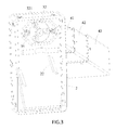
- the driving device of the electric lifting vertical column in the present invention includes a motor shell and a motor 1, the motor shell comprises a bottom box 2 and a bottom plate 3; the lifting vertical column includes the inner tube 41, the middle tube 42 and the outer tube 43 and the gearing rod 44, the motor 1 drives the gearing device which brings along the lifting vertical column going up and down; the gearing device comprises a turbine 31, a turbine connecting head 32 and a gearing rod joint 33 which are sequentially connected together; the worm 11 connected with the output shaft of the motor 1 drives the turbine 31 to rotate; the bottom of the turbine 31 is fixed with gearing grooves 311.
- the gearing bulges 321 are set corresponding to the gearing grooves 311 on the top of the turbine connecting head 32, the gearing bulges 321 are cylindrical, and the gearing bulges 321 are uniformly distributed on the circular top surface of the turbine connecting head 32, the gearing grooves 311 are hollow cylinder and distributed correspondingly to the gearing bulges 321, the gearing bulges 321 are embedded inner of the gearing grooves 311 to realize the gearing procedure, the fixing plates 35 are set on the bottom box 2, the through hole is set on the middle of the fixing plates 35, the bottom of fixing plates 35 contact to the gearing rod joint 33, the turbine connecting head 32 passes through the through hole on the middle of the fixing plates 35 and connects to the gearing rod joint 33, the turbine 31 sequentially drives the turbine connecting head 32 and the gearing rod joint 33 to rotate; and the gearing rod joint 33 drives a gearing rod 44 in the lifting vertical column to rotate. It smoothly realizes the lifting procedure of the lifting vertical column.
- the tail pad 21 made of rubber and at least two mutually parallel supporting blocks 22 are arranged on the bottom box 2; the grooves 211 are set corresponding to the tail end of the motor 1 on the tail pad 21, the tail end of the motor 1 is fixed inner of the tail pad 21 by closely matched to the groove 211, wherein the tail pad 21 is used to fix the motor and reduce the vibration and noises.
- the supporting blocks 22 are two iron sheets which are welded on the bottom box 2, the lengths of the supporting blocks 22 are smaller than the length of the motor 1;the elastic supporting block sleeves 23 are sleeved on the supporting blocks 22; the elastic supporting block sleeves 23 are made of rubber, the distance between the elastic supporting block sleeves 23 is less than the width of the motor 1, the motor 1 is closely matched between the pressed elastic supporting block sleeves 23, the lengths of the elastic supporting block sleeves 23 are also smaller than the length of the motor 1; the elastic supporting block sleeves 23 only contact with part of the surface of two sides of the motor 1, the rest surface of the two sides and the whole top side of the motor 1 are not covered by the elastic supporting block sleeves 23, they are all exposed in the air, which is beneficial for sufficient heat dissipation, and it can prolong the service life of the motor 1 effectively.
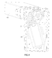
- a secondary briquetting 34 is set on the front of the motor 1, and the limiting grooves 12 are uniformly distributed on the motor 1, preferred, the limiting grooves 12 are distributed circularly as shown in Fig. 4 .
- the limiting bulges are set on the briquetting 34 corresponding to the limiting grooves 12, on one hand, the limiting bulges are embedded into the limiting grooves 12, it can prevent the motor 1 from swinging from side to side when reversing effectively, one the other hand, the top of the briquetting 34 is higher than the top of the motor 1 when the limiting bulges are embedded into the limiting grooves 12, the bottom plate 3 contacts with the briquetting 34 in order to fix the motor on the vertical direction, at last the bottom plate 3 is sealed and connected with the bottom box 2 to realize the whole fixation of the motor.
- the invention can reliably fix the motor and it is beneficial to the sufficient heat dissipation of the motor, it also can prolong the service life of the motor 1
Landscapes
- Engineering & Computer Science (AREA)
- Power Engineering (AREA)
- Connection Of Motors, Electrical Generators, Mechanical Devices, And The Like (AREA)
- Motor Or Generator Frames (AREA)
Applications Claiming Priority (2)
| Application Number | Priority Date | Filing Date | Title |
|---|---|---|---|
| CN 200910154727 CN101710752B (zh) | 2009-12-01 | 2009-12-01 | 电动升降立柱的驱动装置 |
| PCT/CN2010/070528 WO2011066722A1 (zh) | 2009-12-01 | 2010-02-05 | 电动升降立柱的驱动装置 |
Publications (3)
| Publication Number | Publication Date |
|---|---|
| EP2375548A1 true EP2375548A1 (de) | 2011-10-12 |
| EP2375548A4 EP2375548A4 (de) | 2014-04-02 |
| EP2375548B1 EP2375548B1 (de) | 2016-06-22 |
Family
ID=42403516
Family Applications (1)
| Application Number | Title | Priority Date | Filing Date |
|---|---|---|---|
| EP10834155.3A Active EP2375548B1 (de) | 2009-12-01 | 2010-02-05 | Antriebsvorrichtung für eine elektrische hebesäule |
Country Status (4)
| Country | Link |
|---|---|
| EP (1) | EP2375548B1 (de) |
| CN (1) | CN101710752B (de) |
| DK (1) | DK2375548T3 (de) |
| WO (1) | WO2011066722A1 (de) |
Cited By (4)
| Publication number | Priority date | Publication date | Assignee | Title |
|---|---|---|---|---|
| CN105958696A (zh) * | 2016-06-14 | 2016-09-21 | 湖州永盛机械铸造有限公司 | 一种便于后期维护的电动机壳体 |
| EP2944847A3 (de) * | 2014-05-13 | 2016-11-16 | Zhejiang Jiecang Linear Motion Technology Co., Ltd | Aktuator und anwendung davon |
| CN112550399A (zh) * | 2020-12-17 | 2021-03-26 | 福建食惠餐饮管理有限公司 | 一种食品采购用运输装置 |
| EP4262062A4 (de) * | 2021-01-05 | 2024-01-24 | DewertOkin Technology Group Co., Ltd. | Rauscharme leistungsvorrichtung, rauschunterdrückungsmechanismus und rauschunterdrückungsverfahren |
Families Citing this family (8)
| Publication number | Priority date | Publication date | Assignee | Title |
|---|---|---|---|---|
| CN103986268A (zh) * | 2014-05-30 | 2014-08-13 | 浙江捷昌线性驱动科技股份有限公司 | 致动器驱动装置 |
| CN104863937B (zh) * | 2015-04-21 | 2017-10-24 | 浙江捷昌线性驱动科技股份有限公司 | 套管组装结构及升降立柱 |
| CN105909748B (zh) * | 2016-06-23 | 2018-08-21 | 佛山市顺德区睿拓传动系统有限公司 | 具有遇阻停功能的升降机构驱动器 |
| DK3700389T3 (da) | 2017-10-27 | 2023-05-22 | Oelschlaeger Metalltechnik Gmbh | Højdejusterbare rammedele for et møbel, navnlig et højdejusterbart bordben såvel som bordunderstel med sådanne rammedele |
| CN109167475B (zh) * | 2018-11-05 | 2024-02-02 | 宁波南星汽车部件有限公司 | 一种校车车门用电机组件 |
| CN109175976A (zh) * | 2018-11-21 | 2019-01-11 | 山东黄金地产旅游集团有限公司 | 螺纹钢快速紧固装置 |
| CN114465413B (zh) * | 2022-02-16 | 2023-09-22 | 九江萨普智能科技有限公司 | 一种具有过热保护功能的电机控制装置 |
| CN115681370A (zh) * | 2022-10-19 | 2023-02-03 | 宁波爱唯达健康科技有限公司 | 一种刹车机构及升降桌 |
Family Cites Families (7)
| Publication number | Priority date | Publication date | Assignee | Title |
|---|---|---|---|---|
| US2643351A (en) * | 1952-06-05 | 1953-06-23 | Gen Electric | Dynamoelectric machine |
| US6259175B1 (en) * | 1999-11-18 | 2001-07-10 | Dana Corporation | Linear actuator |
| CN1104773C (zh) * | 1999-11-25 | 2003-04-02 | 北京松下通信设备有限公司 | 一种可降低电动机噪音的装置 |
| FR2833775B1 (fr) * | 2001-12-17 | 2004-07-23 | Valeo Climatisation | Bague de maintien et de decouplage du moteur electrique dans son support et procede d'assemblage |
| JP2007524041A (ja) * | 2003-05-06 | 2007-08-23 | リナック エー/エス | アクチュエータ |
| JP2006230046A (ja) * | 2005-02-15 | 2006-08-31 | Jidosha Denki Kogyo Co Ltd | アクチュエータ装置 |
| CN2910888Y (zh) * | 2006-05-16 | 2007-06-13 | 新昌县捷昌医疗设备有限公司 | 层套式自动升降装置 |
-
2009
- 2009-12-01 CN CN 200910154727 patent/CN101710752B/zh active Active
-
2010
- 2010-02-05 EP EP10834155.3A patent/EP2375548B1/de active Active
- 2010-02-05 WO PCT/CN2010/070528 patent/WO2011066722A1/zh not_active Ceased
- 2010-02-05 DK DK10834155.3T patent/DK2375548T3/en active
Cited By (9)
| Publication number | Priority date | Publication date | Assignee | Title |
|---|---|---|---|---|
| EP2944847A3 (de) * | 2014-05-13 | 2016-11-16 | Zhejiang Jiecang Linear Motion Technology Co., Ltd | Aktuator und anwendung davon |
| US10094456B2 (en) | 2014-05-13 | 2018-10-09 | Zhejiang Jiecang Linear Motion Technology Co., Ltd. | Actuator and applications of same |
| EP3739239A1 (de) * | 2014-05-13 | 2020-11-18 | Zhejiang Jiecang Linear Motion Technology Co., Ltd | Aktuator zur umwandlung einer drehbewegung in eine lineare hin- und herbewegung |
| US11028911B2 (en) * | 2014-05-13 | 2021-06-08 | Zhejiang Jiecang Linear Motion Technology Co., Ltd | Actuator and applications of same |
| CN105958696A (zh) * | 2016-06-14 | 2016-09-21 | 湖州永盛机械铸造有限公司 | 一种便于后期维护的电动机壳体 |
| CN105958696B (zh) * | 2016-06-14 | 2019-04-12 | 浙江品创知识产权服务有限公司 | 一种便于后期维护的电动机壳体 |
| CN112550399A (zh) * | 2020-12-17 | 2021-03-26 | 福建食惠餐饮管理有限公司 | 一种食品采购用运输装置 |
| EP4262062A4 (de) * | 2021-01-05 | 2024-01-24 | DewertOkin Technology Group Co., Ltd. | Rauscharme leistungsvorrichtung, rauschunterdrückungsmechanismus und rauschunterdrückungsverfahren |
| US12323031B2 (en) | 2021-01-05 | 2025-06-03 | Dewertokin Technology Group Co., Ltd. | Noise-reduced power device, noise reduction mechanism, and noise reduction method |
Also Published As
| Publication number | Publication date |
|---|---|
| EP2375548B1 (de) | 2016-06-22 |
| EP2375548A4 (de) | 2014-04-02 |
| CN101710752B (zh) | 2012-02-08 |
| WO2011066722A1 (zh) | 2011-06-09 |
| CN101710752A (zh) | 2010-05-19 |
| DK2375548T3 (en) | 2016-09-12 |
Similar Documents
| Publication | Publication Date | Title |
|---|---|---|
| EP2375548B1 (de) | Antriebsvorrichtung für eine elektrische hebesäule | |
| PT1785123E (pt) | Superfície de suporte do doente para uma mesa de operações | |
| CN209845546U (zh) | 一种电动车控制器mos管固定结构 | |
| CN208070673U (zh) | 新型往复送料装置 | |
| CN201554830U (zh) | 一种多连杆驱动机构 | |
| CN202871956U (zh) | 一种可调节耦合度的腔体耦合器 | |
| CN204243993U (zh) | 一种用于升降立柱的电机装置 | |
| CN211530885U (zh) | 一种微型电机的安装结构 | |
| CN214376108U (zh) | 一种笔记本用组合式绝缘片 | |
| CN202065430U (zh) | 多连杆驱动机构 | |
| CN211924832U (zh) | 一种用于电动推杆的扭矩传递消音结构 | |
| CN203826274U (zh) | 负荷开关及其绝缘主轴 | |
| CN210756416U (zh) | 一种新型丝杆导轨机构 | |
| CN210608837U (zh) | 一种绝对值编码器电机 | |
| CN210469013U (zh) | 一种便于拆装维护的电机轴 | |
| CN207272503U (zh) | 一种线缆接头自动焊压设备 | |
| CN221886184U (zh) | 一种减速机电机 | |
| CN220495167U (zh) | 一种长度可调式慢性创面支被架 | |
| CN202197474U (zh) | 一种led驱动装置 | |
| CN222937530U (zh) | 空气源热泵的稳定结构 | |
| CN218548506U (zh) | 一种电池模组装配设备 | |
| CN213151820U (zh) | 一种直线驱动机构 | |
| CN221150898U (zh) | 一种电力节能金具 | |
| CN217503263U (zh) | 一种清洁能源勘查开发用控制终端 | |
| CN216873627U (zh) | 一种空压机控制器用线路板固定结构 |
Legal Events
| Date | Code | Title | Description |
|---|---|---|---|
| PUAI | Public reference made under article 153(3) epc to a published international application that has entered the european phase |
Free format text: ORIGINAL CODE: 0009012 |
|
| 17P | Request for examination filed |
Effective date: 20110624 |
|
| AK | Designated contracting states |
Kind code of ref document: A1 Designated state(s): AT BE BG CH CY CZ DE DK EE ES FI FR GB GR HR HU IE IS IT LI LT LU LV MC MK MT NL NO PL PT RO SE SI SK SM TR |
|
| DAX | Request for extension of the european patent (deleted) | ||
| A4 | Supplementary search report drawn up and despatched |
Effective date: 20140304 |
|
| RIC1 | Information provided on ipc code assigned before grant |
Ipc: H02K 7/116 20060101ALI20140226BHEP Ipc: F16H 25/20 20060101ALI20140226BHEP Ipc: H02K 5/24 20060101AFI20140226BHEP Ipc: A47B 9/04 20060101ALI20140226BHEP |
|
| GRAP | Despatch of communication of intention to grant a patent |
Free format text: ORIGINAL CODE: EPIDOSNIGR1 |
|
| RIC1 | Information provided on ipc code assigned before grant |
Ipc: H02K 5/24 20060101AFI20160115BHEP Ipc: A47B 9/04 20060101ALI20160115BHEP Ipc: F16H 25/20 20060101ALI20160115BHEP Ipc: H02K 7/116 20060101ALI20160115BHEP |
|
| INTG | Intention to grant announced |
Effective date: 20160219 |
|
| GRAS | Grant fee paid |
Free format text: ORIGINAL CODE: EPIDOSNIGR3 |
|
| GRAA | (expected) grant |
Free format text: ORIGINAL CODE: 0009210 |
|
| AK | Designated contracting states |
Kind code of ref document: B1 Designated state(s): AT BE BG CH CY CZ DE DK EE ES FI FR GB GR HR HU IE IS IT LI LT LU LV MC MK MT NL NO PL PT RO SE SI SK SM TR |
|
| REG | Reference to a national code |
Ref country code: GB Ref legal event code: FG4D |
|
| REG | Reference to a national code |
Ref country code: CH Ref legal event code: EP |
|
| REG | Reference to a national code |
Ref country code: IE Ref legal event code: FG4D |
|
| REG | Reference to a national code |
Ref country code: AT Ref legal event code: REF Ref document number: 808171 Country of ref document: AT Kind code of ref document: T Effective date: 20160715 |
|
| REG | Reference to a national code |
Ref country code: DE Ref legal event code: R096 Ref document number: 602010034216 Country of ref document: DE |
|
| REG | Reference to a national code |
Ref country code: DK Ref legal event code: T3 Effective date: 20160905 |
|
| REG | Reference to a national code |
Ref country code: SE Ref legal event code: TRGR |
|
| REG | Reference to a national code |
Ref country code: LT Ref legal event code: MG4D |
|
| REG | Reference to a national code |
Ref country code: NL Ref legal event code: MP Effective date: 20160622 |
|
| PG25 | Lapsed in a contracting state [announced via postgrant information from national office to epo] |
Ref country code: LT Free format text: LAPSE BECAUSE OF FAILURE TO SUBMIT A TRANSLATION OF THE DESCRIPTION OR TO PAY THE FEE WITHIN THE PRESCRIBED TIME-LIMIT Effective date: 20160622 Ref country code: NO Free format text: LAPSE BECAUSE OF FAILURE TO SUBMIT A TRANSLATION OF THE DESCRIPTION OR TO PAY THE FEE WITHIN THE PRESCRIBED TIME-LIMIT Effective date: 20160922 |
|
| REG | Reference to a national code |
Ref country code: AT Ref legal event code: MK05 Ref document number: 808171 Country of ref document: AT Kind code of ref document: T Effective date: 20160622 |
|
| PG25 | Lapsed in a contracting state [announced via postgrant information from national office to epo] |
Ref country code: LV Free format text: LAPSE BECAUSE OF FAILURE TO SUBMIT A TRANSLATION OF THE DESCRIPTION OR TO PAY THE FEE WITHIN THE PRESCRIBED TIME-LIMIT Effective date: 20160622 Ref country code: HR Free format text: LAPSE BECAUSE OF FAILURE TO SUBMIT A TRANSLATION OF THE DESCRIPTION OR TO PAY THE FEE WITHIN THE PRESCRIBED TIME-LIMIT Effective date: 20160622 Ref country code: GR Free format text: LAPSE BECAUSE OF FAILURE TO SUBMIT A TRANSLATION OF THE DESCRIPTION OR TO PAY THE FEE WITHIN THE PRESCRIBED TIME-LIMIT Effective date: 20160923 Ref country code: NL Free format text: LAPSE BECAUSE OF FAILURE TO SUBMIT A TRANSLATION OF THE DESCRIPTION OR TO PAY THE FEE WITHIN THE PRESCRIBED TIME-LIMIT Effective date: 20160622 |
|
| PG25 | Lapsed in a contracting state [announced via postgrant information from national office to epo] |
Ref country code: EE Free format text: LAPSE BECAUSE OF FAILURE TO SUBMIT A TRANSLATION OF THE DESCRIPTION OR TO PAY THE FEE WITHIN THE PRESCRIBED TIME-LIMIT Effective date: 20160622 Ref country code: RO Free format text: LAPSE BECAUSE OF FAILURE TO SUBMIT A TRANSLATION OF THE DESCRIPTION OR TO PAY THE FEE WITHIN THE PRESCRIBED TIME-LIMIT Effective date: 20160622 Ref country code: CZ Free format text: LAPSE BECAUSE OF FAILURE TO SUBMIT A TRANSLATION OF THE DESCRIPTION OR TO PAY THE FEE WITHIN THE PRESCRIBED TIME-LIMIT Effective date: 20160622 Ref country code: IT Free format text: LAPSE BECAUSE OF FAILURE TO SUBMIT A TRANSLATION OF THE DESCRIPTION OR TO PAY THE FEE WITHIN THE PRESCRIBED TIME-LIMIT Effective date: 20160622 Ref country code: SK Free format text: LAPSE BECAUSE OF FAILURE TO SUBMIT A TRANSLATION OF THE DESCRIPTION OR TO PAY THE FEE WITHIN THE PRESCRIBED TIME-LIMIT Effective date: 20160622 Ref country code: IS Free format text: LAPSE BECAUSE OF FAILURE TO SUBMIT A TRANSLATION OF THE DESCRIPTION OR TO PAY THE FEE WITHIN THE PRESCRIBED TIME-LIMIT Effective date: 20161022 |
|
| REG | Reference to a national code |
Ref country code: FR Ref legal event code: PLFP Year of fee payment: 8 |
|
| PG25 | Lapsed in a contracting state [announced via postgrant information from national office to epo] |
Ref country code: SM Free format text: LAPSE BECAUSE OF FAILURE TO SUBMIT A TRANSLATION OF THE DESCRIPTION OR TO PAY THE FEE WITHIN THE PRESCRIBED TIME-LIMIT Effective date: 20160622 Ref country code: AT Free format text: LAPSE BECAUSE OF FAILURE TO SUBMIT A TRANSLATION OF THE DESCRIPTION OR TO PAY THE FEE WITHIN THE PRESCRIBED TIME-LIMIT Effective date: 20160622 Ref country code: ES Free format text: LAPSE BECAUSE OF FAILURE TO SUBMIT A TRANSLATION OF THE DESCRIPTION OR TO PAY THE FEE WITHIN THE PRESCRIBED TIME-LIMIT Effective date: 20160622 Ref country code: PL Free format text: LAPSE BECAUSE OF FAILURE TO SUBMIT A TRANSLATION OF THE DESCRIPTION OR TO PAY THE FEE WITHIN THE PRESCRIBED TIME-LIMIT Effective date: 20160622 Ref country code: BE Free format text: LAPSE BECAUSE OF FAILURE TO SUBMIT A TRANSLATION OF THE DESCRIPTION OR TO PAY THE FEE WITHIN THE PRESCRIBED TIME-LIMIT Effective date: 20160622 Ref country code: PT Free format text: LAPSE BECAUSE OF FAILURE TO SUBMIT A TRANSLATION OF THE DESCRIPTION OR TO PAY THE FEE WITHIN THE PRESCRIBED TIME-LIMIT Effective date: 20161024 |
|
| REG | Reference to a national code |
Ref country code: DE Ref legal event code: R097 Ref document number: 602010034216 Country of ref document: DE |
|
| PLBE | No opposition filed within time limit |
Free format text: ORIGINAL CODE: 0009261 |
|
| STAA | Information on the status of an ep patent application or granted ep patent |
Free format text: STATUS: NO OPPOSITION FILED WITHIN TIME LIMIT |
|
| 26N | No opposition filed |
Effective date: 20170323 |
|
| PG25 | Lapsed in a contracting state [announced via postgrant information from national office to epo] |
Ref country code: SI Free format text: LAPSE BECAUSE OF FAILURE TO SUBMIT A TRANSLATION OF THE DESCRIPTION OR TO PAY THE FEE WITHIN THE PRESCRIBED TIME-LIMIT Effective date: 20160622 |
|
| PG25 | Lapsed in a contracting state [announced via postgrant information from national office to epo] |
Ref country code: MC Free format text: LAPSE BECAUSE OF FAILURE TO SUBMIT A TRANSLATION OF THE DESCRIPTION OR TO PAY THE FEE WITHIN THE PRESCRIBED TIME-LIMIT Effective date: 20160622 |
|
| REG | Reference to a national code |
Ref country code: CH Ref legal event code: PL |
|
| PG25 | Lapsed in a contracting state [announced via postgrant information from national office to epo] |
Ref country code: LI Free format text: LAPSE BECAUSE OF NON-PAYMENT OF DUE FEES Effective date: 20170228 Ref country code: CH Free format text: LAPSE BECAUSE OF NON-PAYMENT OF DUE FEES Effective date: 20170228 |
|
| REG | Reference to a national code |
Ref country code: IE Ref legal event code: MM4A |
|
| PG25 | Lapsed in a contracting state [announced via postgrant information from national office to epo] |
Ref country code: LU Free format text: LAPSE BECAUSE OF NON-PAYMENT OF DUE FEES Effective date: 20170205 |
|
| REG | Reference to a national code |
Ref country code: FR Ref legal event code: PLFP Year of fee payment: 9 |
|
| PG25 | Lapsed in a contracting state [announced via postgrant information from national office to epo] |
Ref country code: IE Free format text: LAPSE BECAUSE OF NON-PAYMENT OF DUE FEES Effective date: 20170205 |
|
| PG25 | Lapsed in a contracting state [announced via postgrant information from national office to epo] |
Ref country code: MT Free format text: LAPSE BECAUSE OF NON-PAYMENT OF DUE FEES Effective date: 20170205 |
|
| PG25 | Lapsed in a contracting state [announced via postgrant information from national office to epo] |
Ref country code: HU Free format text: LAPSE BECAUSE OF FAILURE TO SUBMIT A TRANSLATION OF THE DESCRIPTION OR TO PAY THE FEE WITHIN THE PRESCRIBED TIME-LIMIT; INVALID AB INITIO Effective date: 20100205 |
|
| PG25 | Lapsed in a contracting state [announced via postgrant information from national office to epo] |
Ref country code: BG Free format text: LAPSE BECAUSE OF FAILURE TO SUBMIT A TRANSLATION OF THE DESCRIPTION OR TO PAY THE FEE WITHIN THE PRESCRIBED TIME-LIMIT Effective date: 20160622 |
|
| PG25 | Lapsed in a contracting state [announced via postgrant information from national office to epo] |
Ref country code: CY Free format text: LAPSE BECAUSE OF NON-PAYMENT OF DUE FEES Effective date: 20160622 |
|
| PG25 | Lapsed in a contracting state [announced via postgrant information from national office to epo] |
Ref country code: MK Free format text: LAPSE BECAUSE OF FAILURE TO SUBMIT A TRANSLATION OF THE DESCRIPTION OR TO PAY THE FEE WITHIN THE PRESCRIBED TIME-LIMIT Effective date: 20160622 |
|
| PG25 | Lapsed in a contracting state [announced via postgrant information from national office to epo] |
Ref country code: TR Free format text: LAPSE BECAUSE OF FAILURE TO SUBMIT A TRANSLATION OF THE DESCRIPTION OR TO PAY THE FEE WITHIN THE PRESCRIBED TIME-LIMIT Effective date: 20160622 |
|
| P01 | Opt-out of the competence of the unified patent court (upc) registered |
Effective date: 20231018 |
|
| PGFP | Annual fee paid to national office [announced via postgrant information from national office to epo] |
Ref country code: DE Payment date: 20250212 Year of fee payment: 16 |
|
| PGFP | Annual fee paid to national office [announced via postgrant information from national office to epo] |
Ref country code: DK Payment date: 20250130 Year of fee payment: 16 Ref country code: FI Payment date: 20250123 Year of fee payment: 16 |
|
| PGFP | Annual fee paid to national office [announced via postgrant information from national office to epo] |
Ref country code: SE Payment date: 20250217 Year of fee payment: 16 |
|
| PGFP | Annual fee paid to national office [announced via postgrant information from national office to epo] |
Ref country code: FR Payment date: 20250225 Year of fee payment: 16 |
|
| PGFP | Annual fee paid to national office [announced via postgrant information from national office to epo] |
Ref country code: GB Payment date: 20250221 Year of fee payment: 16 |