EP2375652A1 - Système redondant de connexion au réseau pour dispositifs dotés d'une capacité de réseau en cascade et procédé appliqué au système - Google Patents
Système redondant de connexion au réseau pour dispositifs dotés d'une capacité de réseau en cascade et procédé appliqué au système Download PDFInfo
- Publication number
- EP2375652A1 EP2375652A1 EP10158150A EP10158150A EP2375652A1 EP 2375652 A1 EP2375652 A1 EP 2375652A1 EP 10158150 A EP10158150 A EP 10158150A EP 10158150 A EP10158150 A EP 10158150A EP 2375652 A1 EP2375652 A1 EP 2375652A1
- Authority
- EP
- European Patent Office
- Prior art keywords
- network
- connection
- ports
- port
- networking
- Prior art date
- Legal status (The legal status is an assumption and is not a legal conclusion. Google has not performed a legal analysis and makes no representation as to the accuracy of the status listed.)
- Granted
Links
Images



Classifications
-
- H—ELECTRICITY
- H04—ELECTRIC COMMUNICATION TECHNIQUE
- H04L—TRANSMISSION OF DIGITAL INFORMATION, e.g. TELEGRAPHIC COMMUNICATION
- H04L45/00—Routing or path finding of packets in data switching networks
- H04L45/22—Alternate routing
-
- H—ELECTRICITY
- H04—ELECTRIC COMMUNICATION TECHNIQUE
- H04L—TRANSMISSION OF DIGITAL INFORMATION, e.g. TELEGRAPHIC COMMUNICATION
- H04L43/00—Arrangements for monitoring or testing data switching networks
- H04L43/08—Monitoring or testing based on specific metrics, e.g. QoS, energy consumption or environmental parameters
- H04L43/0805—Monitoring or testing based on specific metrics, e.g. QoS, energy consumption or environmental parameters by checking availability
- H04L43/0811—Monitoring or testing based on specific metrics, e.g. QoS, energy consumption or environmental parameters by checking availability by checking connectivity
-
- H—ELECTRICITY
- H04—ELECTRIC COMMUNICATION TECHNIQUE
- H04L—TRANSMISSION OF DIGITAL INFORMATION, e.g. TELEGRAPHIC COMMUNICATION
- H04L45/00—Routing or path finding of packets in data switching networks
- H04L45/18—Loop-free operations
-
- H—ELECTRICITY
- H04—ELECTRIC COMMUNICATION TECHNIQUE
- H04L—TRANSMISSION OF DIGITAL INFORMATION, e.g. TELEGRAPHIC COMMUNICATION
- H04L45/00—Routing or path finding of packets in data switching networks
- H04L45/28—Routing or path finding of packets in data switching networks using route fault recovery
Definitions
- the present invention generally relates to a redundant system for devices with network capability and a method for the same. More particularly, the invention is to establish a redundant connection for the networking devices by defining the roles of ports for each network node.
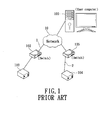
- FIG. 1 shows a framework of a conventional linear-type network.
- a user computer 101 connects to a remote network device via network 10.
- the remote network device may be one or more industrial control machines 103, 104, which are used to control various terminal devices.
- the industrial control machine 103 is connected to the network 10 through a network switch 102, and the machine 104 is through a network switch 105.
- the connection 1 or connection 2 provides no any redundant mechanism. If the connection 1 or connection 2 meets any interruption event, the user computer 101 may not access any one of the industrial control machine 103, 104 via the network 10.
- any device on the connection 1 fails, for example, the network switch 102 is caused damage, the user computer 101 likely fails to access the industrial control machine.
- connection 1 and the connection 2 are mutually redundant connection.
- any terminal device simultaneously has two outward connections (1, 2) through the industrial control machines 103 and 104. If the original connection 1 meets any problem, the connection 2 may take over the connection in order to accomplish the redundant connection. Therefore, the various networking behaviors may not be influenced.
- a router or a switch many computers' network connections may be influenced if any device fails.
- the network switch 102 connected to the industrial control machine 103 fails, the user computer 101 may use the network switch 105 on the connection 2 to control the terminal device. Meanwhile, two or more networking devices may achieve the redundant connection.
- a bus network two connections are adopted for performing the redundancy.
- the ring-type connection may provide its own redundant mechanism.
- a mesh network accomplishes the redundancy by various routing schemes.
- the present invention provides a redundant system for devices with cascade networking capability.
- the system is applicable to various requirements of redundancy for the networking devices under every type of network topology.
- the route for delivering network packets is changed by redefining the roles of network ports of each network node, so as to implement an emergent redundancy. Therefore, the connection for network node or network device may be maintained even though any connection fails or being changed, or any device damages.
- the redundant method for the devices with cascade networking capability has a first step for initializing a network having at least one network node and plural networking devices.
- the each network node at least has two network ports and one device port.
- a device port is connected to one or more networking devices.
- the networking device may be an industrial control machine connected to various terminal devices, or other network devices.
- the each networking device further has at least two network ports respectively connected toward two different network nodes.
- the two network ports on the networking device may simultaneously connect to the ports on the same one network node.
- roles of device ports on each network node may be defined based on the content of the broadcast packets on a local area network.
- the roles may be defined by comparing the broadcast packets. For example, some ports may be defined as forward ports, and some are blocked ports. Every role of port is in charge of different task.
- the definition of each role of port in the present invention may change the network route for each packet, so as to implement the redundancy.
- Each network node periodically broadcasts or receives a connection-confirmation packet which is used for determining whether any connection has change.
- the change may be any failure of connection or device. Any modification of the connection, such as increasing or decreasing the device on the network, may result in the change. Since the connection is changed, the roles of ports on the relevant network node(s) are re-defined. Meanwhile, the route for delivering the packets is modified for avoiding the original problematic route for redundancy.
- a redundant system in accordance with the present invention is further provided to apply the mentioned method for the devices with cascade networking capability.
- the network system has at least two network nodes. Each node includes two or more network ports which are used to connect to other nodes. One or more device ports are also included for connecting the networking device(s). One or more networking devices are included in the system. Each networking device includes at least two network ports respectively connected to the device ports on the network node.
- an initialized process is performed to define the roles of the device ports based on a network protocol as the network node(s) and the networking device(s) are initially connected. After that, the roles may be re-defined as any connection changes by detection of the broadcast packets. Therefore, the packets routing may be modified.
- the two network ports of one networking device are respectively connected to the same one network node having at least two different device ports.
- a plurality of networking devices are particularly adapted.
- Each networking device has two different network ports connected to the different device ports, so as to form at least one group of networking devices.
- the network node(s) and the plural networking devices form a local area network which is initially established by defining the roles of device ports. When the change of the connection is detected, the roles of ports are re-defined in order to modify the packet routing for redundancy.
- Fig. 1 shows a schematic diagram of a conventional linear-type network framework
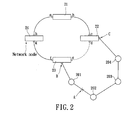
- Fig. 2 is one of the schematic diagrams of the network framework of the redundant system for devices with cascade networking capability
- Fig. 3 is second schematic diagram of the network framework of the redundant system for devices with cascade networking capability
- Fig. 4 is third schematic diagram of the network framework of the redundant system for devices with cascade networking capability
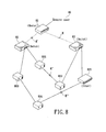
- Fig. 5 is fourth schematic diagram of the network framework of the redundant system for devices with cascade networking capability
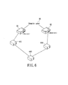
- Fig. 6 is a schematic diagram illustrating the network framework of the redundant system for devices with cascade networking capability in accordance with the present invention
- Fig. 7 is a schematic diagram illustrating the network framework of the redundant system for devices with cascade networking capability in accordance with the present invention.
- Fig. 8 is a schematic diagram illustrating the network framework of the redundant system with for devices with cascade networking capability in accordance with the present invention.
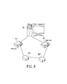
- Fig. 9 is a schematic diagram illustrating the network framework of the redundant system for devices with cascade networking capability in accordance with the present invention.
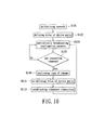
- Fig. 10 is a flow chart illustrating the redundant method for devices with cascade networking capability in accordance with the present invention.
- Fig. 2 shows a framework of the network-connection redundant system for devices with cascade networking capability.
- the system particularly includes a ring-type network formed by a plurality of network nodes 21,22,23,24.
- the network node is especially a network switch.
- a plurality of networking devices 201,202,203,204 interconnected between the network node 22 and the network node 23 are also included.
- the network device is especially an industrial control machine for controlling the various terminal devices, or other types of network devices. Therefore, another type of ring-type network is formed.
- each network node (21, 22, 23, or 24) has at least two network ports.
- the shown network node 21 has a port a and a port b, which are respectively connected to a port h of network node 24 and a port c of network node 22. Therefore, a ring-type network with redundant capability is formed.
- the interconnected ports a, b, c, d, e, f, g, h are compared using their MAC addresses in order to define their roles of ports. In the meantime, the intrinsic broadcast storm for the ring-type network should be avoided.
- one of the ports is defined as a blocked port, and others are defined as forward ports. While any one connection fails, that is the network packet may not reach one of the network nodes, the roles of ports may be re-defined. That means the blocked port may be transformed to the forward port. However, the port close to the point of failure shall be transformed to the blocked port in order to maintain the well connection. The remote user(s) may continuously access the resources in this network.
- the current embodiment shown in Fig. 2 provides the mentioned redundant scheme for the network nodes (the switches) thereon, additionally, the networking devices in the same network may also work under this redundancy.
- Each of the shown networking devices 201,202,203,204 at least has different network ports.
- the network ports are interconnected with each other.
- a cascade network is formed as a local area network with the network node 22 and network node23. Under this cascade network, the interconnected networking devices 201, 202, 203, 204 are connected toward the device ports B and C of the network node.
- the device port B may be defined as a blocked port and the packets may not be forwarded to the networking devices 201,202,203,204 via this port. However, the packets may be forwarded through the network node to the networking devices 201,202,203,204 since the device port C is defined as a forward port. It is worth noting that the defined blocked port and forward port can prevent the broadcast storm subject to the packets looping in the ring-type network.
- each network node will periodically broadcast some packets over the network, such as a connection-confirmation packet which is used to check the connection.
- a connection-confirmation packet which is used to check the connection.
- Each node may also receive the packets from the others in order to identify with each other.
- connection fails, for example, a connect point A is broken, both the networking devices 201 and 202 across the two terminals of point A will aware the passing packets may not arrive to the other end. The failure indicates that the external packets may not reach the networking device 201, for example. In the meantime, the blocked port B does not receive the connection-confirmation packet from the forward port C in a predetermined period of time. It shows that any failure of connection happens.
- the device port B in accordance with the present invention, may be transformed to a forward port, so the packets may reach the networking devices 202, 203, 204 via the device port C, and further reach to the networking device 201 via the device port B.
- Fig. 3 shows another embodiment of the framework of the redundant system for the devices with cascade networking capability.
- a network node is interconnected to two different local area networks which are different types of network. They are one typical ring-type network having network nodes 31,32,33,34 and the other more complex network having network nodes 35,36,37,38.
- This complex network may be a network type ruled by a Rapid Spanning Tree Protocol (RSTP).
- RSTP Rapid Spanning Tree Protocol
- the role of each device port will be defined according to the communication protocol. Then the broadcast packet there-between may be used to detect whether any connection changes or not. The changes of connection may be a connection failure, device failure, or connection modification. After that, the roles of ports will be re-defined in order to modify the packets routing.
- the device port B' is initially defined as a blocked port, so the external packets may not pass through this device port B' and reach the networking devices 301,302,303.
- the device port C' is initially defined as a forward port.
- a connect point A' interrupts, and the networking device 301 fails to connect to external, the device port B' will be transformed to a forward port and the passing packets may reach the networking device 301.
- the example shows the re-definition of roles of ports makes the network to accomplish a redundant mechanism.
- Fig. 4 showing a schematic diagram of framework of the redundant system in accordance with the present invention.
- the invention may be applied to a network with single network node and its connected networking devices.
- a network node 40 provides a network gateway to external for a plurality of networking devices 401,402,403,404,405,406,407,408,409,410.
- the network node 40 has two network ports which are respectively connected to two different network nodes, and has device ports to connect with devices in the local area network.
- each of the networking devices 401,402,403,404 has two network ports.
- the devices 401,402,403,404 are interconnected to form a linear type network.
- the two end of the network are respectively connected to the device ports D, E of the network node 40.
- the like connection forms a network group.
- the interconnected networking devices 405, 406, 407 form another local area network (the other network group), and two ends of the network respectively connect to the device ports F,G of the same network node 40.
- the networking devices 408,409,410 also form another network group, and two ends of the local area network respectively connect to the device ports H,I.
- the two ends of the each network group connect to the same network node 40.
- the device ports of the network node 40 are firstly defined as different roles of ports. Therefore, it provides the mentioned redundant mechanism.
- the device port D is initially defined as a blocked port
- the device port E is defined as a forward port. Then the looping of packets among the devices within one group can be avoided.
- the ID or any number indicating the each port can be referred to determine which port is the blocked port or the forward port. In practice, the number, such as its ID number or MAC address, for each port is compared with another one, and the bigger one may be defined as a blocked port and the smaller one may be a forward port. Therefore, the shown device ports F, G, H, I have their own roles.
- connection is broken, device is failed, or connection is modified
- the roles of the device ports need to be re-defined, that is the original blocked port may be redefined as the forward port. Then a redundant route will be established for the network packets.
- the network nodes 51, 52 are respectively connected to the networking devices 501, 502, 503 via the device ports.
- the device port J of the network node 51 is initially defined as a blocked port.
- the device port K of the network node 52 is defined as a forward port.
- a network node 53 is temporarily added in the network, and the connection to the networking device 502 is redirected to the network node 53.
- a connect point A" is then interrupted since the original connection is changed.
- the system may detect the change, that means the device port J may not receive any packet from the device port K.
- the device port J is then re-defined as a forward port. Therefore, the networking device 501 may be accessed from a remote user.
- connection 5 is established between the network node 52 and the network node 53.
- the roles of both the device port K and the device port L will be respectively re-defined as the blocked port and the forward port.
- the network framework is changed.
- the system will detect the change from the broadcast packet. At this moment, the ports of each network node are re-defined.
- the mentioned network node is preferably the network switch, which is used for forwarding the packets in the network, and for the gateway among the local area networks. Any remote user may access the networking device(s) through the network switch over the network.
- the each networking device at least has two network ports respectively connected to the different device ports.
- One of the objectives of the invention is to define the roles of ports on the different or the same network switch so as to provide the redundant mechanism.
- a remote user 60 simultaneously connects to two different network switches 61, 62 over different connections.
- the plurality of industrial control machines 601, 602, 603 form a linear-type network, and the two ends of the network are respectively connected to different network switches 61, 62.
- These two network switches 61, 62 implement the redundant mechanism.
- the broadcast packets among the industrial control machines 601,602,603 may be used for checking the status of connection.
- the change of the connection may be any failure occurred to the connection among the industrial control machines 601, 602, 603, any failure of device, or any change to the network framework that requires modification.
- the blocked port may be transformed to the forward port since it does not receive the packet from the forward port in a predetermined period of time.
- the roles of ports of the network switch may be re-defined in order to maintain the connection.
- Fig. 7 shows an embodiment for the diagram shown in Fig. 2 .
- a plurality of network switches 71, 72, 73, 74 form a ring-type network.
- a local area network is constituted of a plurality of networking devices, such as the industrial control machines 701, 702, 703, and two network switches 73, 74.
- the device port of the network switch 73 and the device port of the network switch 74 are respectively defined as blocked port and forward port as the network is initially established.
- the defined blocked port may not receive any packet from the adjacent device or forward port in a period of time. According to the present invention, the blocked port will be transformed to a forward port.
- Fig. 8 shows an embodiment of the redundant system for the devices with cascade networking capability.
- Another local area network is constituted of the other industrial control machines 803, 804 and the network device 805 which are connected to the network switch 82 and the network switch 83. It is featured that the system provides a various and flexible redundant environment.
- a remote user 80 connects to the different network switches 82, 83 through a router 81 over the network, in order to access the industrial control machines 801, 802, 803, 804 or the network device 805.
- the other one connection may continue the connection.
- the connect point M" between the industrial control machine 801 and the industrial control machine 802 is broken, the route there-between may be modified by re-defining the roles of ports in order to implement the redundancy.
- Fig. 9 depicts another embodiment in accordance with the present invention.
- a user computer 90 is equipped with two network cards, which are respectively connected to two different network switches 91, 92.
- the two connections form a local area network, on which an industrial control machine 901 and an industrial control machine 902 are respectively connected to the network switches 91 and 92.
- the user computer 90 may have its redundancy as the two connections connected with the network switches 91 and 92.
- the roles of ports of the network node such as the network switch, may be instantly re-defined as another role so as to modify the packet routing when the original connection changes.
- the instant transformation of the roles of ports implements the redundant mechanism.
- the related method applied to the redundant system is illustrated in Fig. 10 .
- One or more network nodes and one or more networking devices form a network.
- Each network node at least has two network ports and a plurality of device ports.
- Each networking device at least has two network ports connected with the same one or two different network nodes.
- the network is initialized, and the roles of the device ports on each network node are initially defined according to the comparison result of the packets broadcasted among the devices.
- the roles of ports include a forward port and a blocked port (step S 103).
- each network node periodically broadcasts or receives the connection-confirmation packet in order to determine whether any connection meets change or not. That means it's to confirm the connection change by determining whether or not receiving the connection-confirmation packet and its corresponding response (step S107).
- step S107 Such as any failure of connection, damage of device, or any modification of network framework, it makes the connection-confirmation packet or its response abnormal.
- step S105 Since there is no change by confirming the connection-confirmation packet and its response (no), the step in the method goes to step S105 and continues the detection.
- the each network node may determine whether there is any change or not by a process of confirming the broadcast packet. If any connection change appears (yes), the next step is to confirm a type of the change, such as the mentioned failure of connection, damage of device or modification of connection (step S109).
- step S111 the message relating the connection change and the relevant status of the ports of networking device are referred to re-define the roles of device ports of each network node. Then a redundant connection is established in step S 113. In the meantime, the packet routing may be modified in order to avoid the problematic portion of the connection.
- the redundant system and its method for devices with cascade networking capability are featured that the definition and re-definition of the roles of the device ports of the network node(s) implement by modifying the packet routing.
Landscapes
- Engineering & Computer Science (AREA)
- Computer Networks & Wireless Communication (AREA)
- Signal Processing (AREA)
- Environmental & Geological Engineering (AREA)
- Data Exchanges In Wide-Area Networks (AREA)
Priority Applications (1)
| Application Number | Priority Date | Filing Date | Title |
|---|---|---|---|
| EP10158150.2A EP2375652B1 (fr) | 2010-03-29 | 2010-03-29 | Système redondant de connexion au réseau pour dispositifs dotés d'une capacité de réseau en cascade et procédé appliqué au système |
Applications Claiming Priority (1)
| Application Number | Priority Date | Filing Date | Title |
|---|---|---|---|
| EP10158150.2A EP2375652B1 (fr) | 2010-03-29 | 2010-03-29 | Système redondant de connexion au réseau pour dispositifs dotés d'une capacité de réseau en cascade et procédé appliqué au système |
Publications (2)
| Publication Number | Publication Date |
|---|---|
| EP2375652A1 true EP2375652A1 (fr) | 2011-10-12 |
| EP2375652B1 EP2375652B1 (fr) | 2018-05-30 |
Family
ID=42246330
Family Applications (1)
| Application Number | Title | Priority Date | Filing Date |
|---|---|---|---|
| EP10158150.2A Active EP2375652B1 (fr) | 2010-03-29 | 2010-03-29 | Système redondant de connexion au réseau pour dispositifs dotés d'une capacité de réseau en cascade et procédé appliqué au système |
Country Status (1)
| Country | Link |
|---|---|
| EP (1) | EP2375652B1 (fr) |
Citations (2)
| Publication number | Priority date | Publication date | Assignee | Title |
|---|---|---|---|---|
| US20060245351A1 (en) * | 2005-05-02 | 2006-11-02 | Moni Pande | Method, apparatus, and system for improving ethernet ring convergence time |
| EP2096800A1 (fr) * | 2008-02-28 | 2009-09-02 | NEC Corporation | Système de réseau local en boucle de couche 2 et son procédé de gestion |
Family Cites Families (1)
| Publication number | Priority date | Publication date | Assignee | Title |
|---|---|---|---|---|
| US7911938B2 (en) * | 2006-01-20 | 2011-03-22 | Cisco Technology, Inc. | System and method for preventing loops in the presence of control plane failures |
-
2010
- 2010-03-29 EP EP10158150.2A patent/EP2375652B1/fr active Active
Patent Citations (2)
| Publication number | Priority date | Publication date | Assignee | Title |
|---|---|---|---|---|
| US20060245351A1 (en) * | 2005-05-02 | 2006-11-02 | Moni Pande | Method, apparatus, and system for improving ethernet ring convergence time |
| EP2096800A1 (fr) * | 2008-02-28 | 2009-09-02 | NEC Corporation | Système de réseau local en boucle de couche 2 et son procédé de gestion |
Also Published As
| Publication number | Publication date |
|---|---|
| EP2375652B1 (fr) | 2018-05-30 |
Similar Documents
| Publication | Publication Date | Title |
|---|---|---|
| US8411690B2 (en) | Preventing data traffic connectivity between endpoints of a network segment | |
| US6581166B1 (en) | Network fault detection and recovery | |
| CN102821050B (zh) | 一种快速生成树协议应用于单环网拓扑的处理方法 | |
| CN103684716B (zh) | 用于在工业通信网络中进行消息传输的方法和通信设备 | |
| EP3297224B1 (fr) | Prévention des boucles de trafic de données associées à la sélection de transitaire désigné | |
| CN101060485B (zh) | 拓扑改变报文的处理方法和处理装置 | |
| US20110164494A1 (en) | Method for operating a virtual router redundancy protocol router and communication system therefor | |
| EP2698948A1 (fr) | Procédé et dispositif pour déterminer une élimination de défaillance sur la base d'un protocole oam | |
| CN112787843B (zh) | 故障节点的检测方法和存储介质及电子装置 | |
| CN111030877A (zh) | 主备设备切换方法和装置 | |
| CN111447101A (zh) | 链路检测方法、装置、计算机设备及存储介质 | |
| US8218433B2 (en) | Monitoring connectivity in ring networks | |
| US20080130503A1 (en) | Method and system for forwarding ethernet frames over redundant networks with all links enabled | |
| US8295164B2 (en) | Network-connection redundant system for devices with cascade networking capability and method applied on the system | |
| CN111585797A (zh) | 以太网链路切换方法、装置、设备及计算机可读存储介质 | |
| US9521073B2 (en) | Enhanced fine-grained overlay transport virtualization multi-homing using per-network authoritative edge device synchronization | |
| US9246796B2 (en) | Transmitting and forwarding data | |
| JP2009003491A (ja) | クラスタシステムにおけるサーバ切り替え方法 | |
| CN102812750B (zh) | 分组传送网络中故障处理方法、分组传送网络及节点 | |
| EP2375652B1 (fr) | Système redondant de connexion au réseau pour dispositifs dotés d'une capacité de réseau en cascade et procédé appliqué au système | |
| WO2018040940A1 (fr) | Réseau à deux couches, et procédé de détection de bouclage de réseau à deux couches | |
| EP2898636B1 (fr) | Procédé de fonctionnement d'un réseau informatique | |
| TWI396408B (zh) | 具串接連網能力的設備之備援系統及其方法 | |
| CN109120521B (zh) | 环形堆叠系统路径切换方法、第一及第二堆叠设备 | |
| CN108259289B (zh) | 一种环网异常保护方法及装置 |
Legal Events
| Date | Code | Title | Description |
|---|---|---|---|
| PUAI | Public reference made under article 153(3) epc to a published international application that has entered the european phase |
Free format text: ORIGINAL CODE: 0009012 |
|
| AK | Designated contracting states |
Kind code of ref document: A1 Designated state(s): AT BE BG CH CY CZ DE DK EE ES FI FR GB GR HR HU IE IS IT LI LT LU LV MC MK MT NL NO PL PT RO SE SI SK SM TR |
|
| AX | Request for extension of the european patent |
Extension state: AL BA ME RS |
|
| 17P | Request for examination filed |
Effective date: 20120330 |
|
| 17Q | First examination report despatched |
Effective date: 20150803 |
|
| REG | Reference to a national code |
Ref country code: DE Ref legal event code: R079 Ref document number: 602010050864 Country of ref document: DE Free format text: PREVIOUS MAIN CLASS: H04L0012560000 Ipc: H04L0012260000 |
|
| GRAP | Despatch of communication of intention to grant a patent |
Free format text: ORIGINAL CODE: EPIDOSNIGR1 |
|
| STAA | Information on the status of an ep patent application or granted ep patent |
Free format text: STATUS: GRANT OF PATENT IS INTENDED |
|
| INTG | Intention to grant announced |
Effective date: 20171222 |
|
| RIC1 | Information provided on ipc code assigned before grant |
Ipc: H04L 12/703 20130101ALI20171208BHEP Ipc: H04L 12/705 20130101ALI20171208BHEP Ipc: H04L 12/26 20060101AFI20171208BHEP Ipc: H04L 12/707 20130101ALI20171208BHEP |
|
| GRAS | Grant fee paid |
Free format text: ORIGINAL CODE: EPIDOSNIGR3 |
|
| GRAA | (expected) grant |
Free format text: ORIGINAL CODE: 0009210 |
|
| STAA | Information on the status of an ep patent application or granted ep patent |
Free format text: STATUS: THE PATENT HAS BEEN GRANTED |
|
| AK | Designated contracting states |
Kind code of ref document: B1 Designated state(s): AT BE BG CH CY CZ DE DK EE ES FI FR GB GR HR HU IE IS IT LI LT LU LV MC MK MT NL NO PL PT RO SE SI SK SM TR |
|
| REG | Reference to a national code |
Ref country code: GB Ref legal event code: FG4D |
|
| REG | Reference to a national code |
Ref country code: CH Ref legal event code: EP |
|
| REG | Reference to a national code |
Ref country code: AT Ref legal event code: REF Ref document number: 1004736 Country of ref document: AT Kind code of ref document: T Effective date: 20180615 |
|
| REG | Reference to a national code |
Ref country code: IE Ref legal event code: FG4D |
|
| REG | Reference to a national code |
Ref country code: DE Ref legal event code: R096 Ref document number: 602010050864 Country of ref document: DE |
|
| REG | Reference to a national code |
Ref country code: NL Ref legal event code: MP Effective date: 20180530 |
|
| REG | Reference to a national code |
Ref country code: LT Ref legal event code: MG4D |
|
| PG25 | Lapsed in a contracting state [announced via postgrant information from national office to epo] |
Ref country code: FI Free format text: LAPSE BECAUSE OF FAILURE TO SUBMIT A TRANSLATION OF THE DESCRIPTION OR TO PAY THE FEE WITHIN THE PRESCRIBED TIME-LIMIT Effective date: 20180530 Ref country code: BG Free format text: LAPSE BECAUSE OF FAILURE TO SUBMIT A TRANSLATION OF THE DESCRIPTION OR TO PAY THE FEE WITHIN THE PRESCRIBED TIME-LIMIT Effective date: 20180830 Ref country code: CY Free format text: LAPSE BECAUSE OF FAILURE TO SUBMIT A TRANSLATION OF THE DESCRIPTION OR TO PAY THE FEE WITHIN THE PRESCRIBED TIME-LIMIT Effective date: 20180530 Ref country code: SE Free format text: LAPSE BECAUSE OF FAILURE TO SUBMIT A TRANSLATION OF THE DESCRIPTION OR TO PAY THE FEE WITHIN THE PRESCRIBED TIME-LIMIT Effective date: 20180530 Ref country code: ES Free format text: LAPSE BECAUSE OF FAILURE TO SUBMIT A TRANSLATION OF THE DESCRIPTION OR TO PAY THE FEE WITHIN THE PRESCRIBED TIME-LIMIT Effective date: 20180530 Ref country code: LT Free format text: LAPSE BECAUSE OF FAILURE TO SUBMIT A TRANSLATION OF THE DESCRIPTION OR TO PAY THE FEE WITHIN THE PRESCRIBED TIME-LIMIT Effective date: 20180530 Ref country code: NO Free format text: LAPSE BECAUSE OF FAILURE TO SUBMIT A TRANSLATION OF THE DESCRIPTION OR TO PAY THE FEE WITHIN THE PRESCRIBED TIME-LIMIT Effective date: 20180830 |
|
| PG25 | Lapsed in a contracting state [announced via postgrant information from national office to epo] |
Ref country code: HR Free format text: LAPSE BECAUSE OF FAILURE TO SUBMIT A TRANSLATION OF THE DESCRIPTION OR TO PAY THE FEE WITHIN THE PRESCRIBED TIME-LIMIT Effective date: 20180530 Ref country code: GR Free format text: LAPSE BECAUSE OF FAILURE TO SUBMIT A TRANSLATION OF THE DESCRIPTION OR TO PAY THE FEE WITHIN THE PRESCRIBED TIME-LIMIT Effective date: 20180831 Ref country code: LV Free format text: LAPSE BECAUSE OF FAILURE TO SUBMIT A TRANSLATION OF THE DESCRIPTION OR TO PAY THE FEE WITHIN THE PRESCRIBED TIME-LIMIT Effective date: 20180530 |
|
| REG | Reference to a national code |
Ref country code: AT Ref legal event code: MK05 Ref document number: 1004736 Country of ref document: AT Kind code of ref document: T Effective date: 20180530 |
|
| PG25 | Lapsed in a contracting state [announced via postgrant information from national office to epo] |
Ref country code: NL Free format text: LAPSE BECAUSE OF FAILURE TO SUBMIT A TRANSLATION OF THE DESCRIPTION OR TO PAY THE FEE WITHIN THE PRESCRIBED TIME-LIMIT Effective date: 20180530 |
|
| PG25 | Lapsed in a contracting state [announced via postgrant information from national office to epo] |
Ref country code: AT Free format text: LAPSE BECAUSE OF FAILURE TO SUBMIT A TRANSLATION OF THE DESCRIPTION OR TO PAY THE FEE WITHIN THE PRESCRIBED TIME-LIMIT Effective date: 20180530 Ref country code: DK Free format text: LAPSE BECAUSE OF FAILURE TO SUBMIT A TRANSLATION OF THE DESCRIPTION OR TO PAY THE FEE WITHIN THE PRESCRIBED TIME-LIMIT Effective date: 20180530 Ref country code: EE Free format text: LAPSE BECAUSE OF FAILURE TO SUBMIT A TRANSLATION OF THE DESCRIPTION OR TO PAY THE FEE WITHIN THE PRESCRIBED TIME-LIMIT Effective date: 20180530 Ref country code: SK Free format text: LAPSE BECAUSE OF FAILURE TO SUBMIT A TRANSLATION OF THE DESCRIPTION OR TO PAY THE FEE WITHIN THE PRESCRIBED TIME-LIMIT Effective date: 20180530 Ref country code: RO Free format text: LAPSE BECAUSE OF FAILURE TO SUBMIT A TRANSLATION OF THE DESCRIPTION OR TO PAY THE FEE WITHIN THE PRESCRIBED TIME-LIMIT Effective date: 20180530 Ref country code: CZ Free format text: LAPSE BECAUSE OF FAILURE TO SUBMIT A TRANSLATION OF THE DESCRIPTION OR TO PAY THE FEE WITHIN THE PRESCRIBED TIME-LIMIT Effective date: 20180530 Ref country code: PL Free format text: LAPSE BECAUSE OF FAILURE TO SUBMIT A TRANSLATION OF THE DESCRIPTION OR TO PAY THE FEE WITHIN THE PRESCRIBED TIME-LIMIT Effective date: 20180530 |
|
| PG25 | Lapsed in a contracting state [announced via postgrant information from national office to epo] |
Ref country code: IT Free format text: LAPSE BECAUSE OF FAILURE TO SUBMIT A TRANSLATION OF THE DESCRIPTION OR TO PAY THE FEE WITHIN THE PRESCRIBED TIME-LIMIT Effective date: 20180530 Ref country code: SM Free format text: LAPSE BECAUSE OF FAILURE TO SUBMIT A TRANSLATION OF THE DESCRIPTION OR TO PAY THE FEE WITHIN THE PRESCRIBED TIME-LIMIT Effective date: 20180530 |
|
| REG | Reference to a national code |
Ref country code: DE Ref legal event code: R097 Ref document number: 602010050864 Country of ref document: DE |
|
| PLBE | No opposition filed within time limit |
Free format text: ORIGINAL CODE: 0009261 |
|
| STAA | Information on the status of an ep patent application or granted ep patent |
Free format text: STATUS: NO OPPOSITION FILED WITHIN TIME LIMIT |
|
| 26N | No opposition filed |
Effective date: 20190301 |
|
| PG25 | Lapsed in a contracting state [announced via postgrant information from national office to epo] |
Ref country code: SI Free format text: LAPSE BECAUSE OF FAILURE TO SUBMIT A TRANSLATION OF THE DESCRIPTION OR TO PAY THE FEE WITHIN THE PRESCRIBED TIME-LIMIT Effective date: 20180530 |
|
| PG25 | Lapsed in a contracting state [announced via postgrant information from national office to epo] |
Ref country code: MC Free format text: LAPSE BECAUSE OF FAILURE TO SUBMIT A TRANSLATION OF THE DESCRIPTION OR TO PAY THE FEE WITHIN THE PRESCRIBED TIME-LIMIT Effective date: 20180530 |
|
| REG | Reference to a national code |
Ref country code: CH Ref legal event code: PL |
|
| PG25 | Lapsed in a contracting state [announced via postgrant information from national office to epo] |
Ref country code: LU Free format text: LAPSE BECAUSE OF NON-PAYMENT OF DUE FEES Effective date: 20190329 |
|
| REG | Reference to a national code |
Ref country code: BE Ref legal event code: MM Effective date: 20190331 |
|
| PG25 | Lapsed in a contracting state [announced via postgrant information from national office to epo] |
Ref country code: LI Free format text: LAPSE BECAUSE OF NON-PAYMENT OF DUE FEES Effective date: 20190331 Ref country code: CH Free format text: LAPSE BECAUSE OF NON-PAYMENT OF DUE FEES Effective date: 20190331 Ref country code: IE Free format text: LAPSE BECAUSE OF NON-PAYMENT OF DUE FEES Effective date: 20190329 |
|
| PG25 | Lapsed in a contracting state [announced via postgrant information from national office to epo] |
Ref country code: BE Free format text: LAPSE BECAUSE OF NON-PAYMENT OF DUE FEES Effective date: 20190331 |
|
| PG25 | Lapsed in a contracting state [announced via postgrant information from national office to epo] |
Ref country code: TR Free format text: LAPSE BECAUSE OF FAILURE TO SUBMIT A TRANSLATION OF THE DESCRIPTION OR TO PAY THE FEE WITHIN THE PRESCRIBED TIME-LIMIT Effective date: 20180530 |
|
| PG25 | Lapsed in a contracting state [announced via postgrant information from national office to epo] |
Ref country code: MT Free format text: LAPSE BECAUSE OF NON-PAYMENT OF DUE FEES Effective date: 20190329 Ref country code: PT Free format text: LAPSE BECAUSE OF FAILURE TO SUBMIT A TRANSLATION OF THE DESCRIPTION OR TO PAY THE FEE WITHIN THE PRESCRIBED TIME-LIMIT Effective date: 20181001 |
|
| PG25 | Lapsed in a contracting state [announced via postgrant information from national office to epo] |
Ref country code: IS Free format text: LAPSE BECAUSE OF FAILURE TO SUBMIT A TRANSLATION OF THE DESCRIPTION OR TO PAY THE FEE WITHIN THE PRESCRIBED TIME-LIMIT Effective date: 20180930 |
|
| PG25 | Lapsed in a contracting state [announced via postgrant information from national office to epo] |
Ref country code: HU Free format text: LAPSE BECAUSE OF FAILURE TO SUBMIT A TRANSLATION OF THE DESCRIPTION OR TO PAY THE FEE WITHIN THE PRESCRIBED TIME-LIMIT; INVALID AB INITIO Effective date: 20100329 |
|
| REG | Reference to a national code |
Ref country code: DE Ref legal event code: R079 Ref document number: 602010050864 Country of ref document: DE Free format text: PREVIOUS MAIN CLASS: H04L0012260000 Ipc: H04L0043000000 |
|
| PG25 | Lapsed in a contracting state [announced via postgrant information from national office to epo] |
Ref country code: MK Free format text: LAPSE BECAUSE OF FAILURE TO SUBMIT A TRANSLATION OF THE DESCRIPTION OR TO PAY THE FEE WITHIN THE PRESCRIBED TIME-LIMIT Effective date: 20180530 |
|
| P01 | Opt-out of the competence of the unified patent court (upc) registered |
Effective date: 20230530 |
|
| PGFP | Annual fee paid to national office [announced via postgrant information from national office to epo] |
Ref country code: GB Payment date: 20260324 Year of fee payment: 17 |
|
| PGFP | Annual fee paid to national office [announced via postgrant information from national office to epo] |
Ref country code: DE Payment date: 20260226 Year of fee payment: 17 |
|
| PGFP | Annual fee paid to national office [announced via postgrant information from national office to epo] |
Ref country code: FR Payment date: 20260324 Year of fee payment: 17 |