EP2376026B1 - Expandierbares wirbelkörper-ersatzsystem - Google Patents
Expandierbares wirbelkörper-ersatzsystem Download PDFInfo
- Publication number
- EP2376026B1 EP2376026B1 EP09768260.3A EP09768260A EP2376026B1 EP 2376026 B1 EP2376026 B1 EP 2376026B1 EP 09768260 A EP09768260 A EP 09768260A EP 2376026 B1 EP2376026 B1 EP 2376026B1
- Authority
- EP
- European Patent Office
- Prior art keywords
- endplate
- implantable device
- central member
- respect
- coupling feature
- Prior art date
- Legal status (The legal status is an assumption and is not a legal conclusion. Google has not performed a legal analysis and makes no representation as to the accuracy of the status listed.)
- Active
Links
Images










Classifications
-
- A—HUMAN NECESSITIES
- A61—MEDICAL OR VETERINARY SCIENCE; HYGIENE
- A61F—FILTERS IMPLANTABLE INTO BLOOD VESSELS; PROSTHESES; DEVICES PROVIDING PATENCY TO, OR PREVENTING COLLAPSING OF, TUBULAR STRUCTURES OF THE BODY, e.g. STENTS; ORTHOPAEDIC, NURSING OR CONTRACEPTIVE DEVICES; FOMENTATION; TREATMENT OR PROTECTION OF EYES OR EARS; BANDAGES, DRESSINGS OR ABSORBENT PADS; FIRST-AID KITS
- A61F2/00—Filters implantable into blood vessels; Prostheses, i.e. artificial substitutes or replacements for parts of the body; Appliances for connecting them with the body; Devices providing patency to, or preventing collapsing of, tubular structures of the body, e.g. stents
- A61F2/02—Prostheses implantable into the body
- A61F2/30—Joints
- A61F2/44—Joints for the spine, e.g. vertebrae, spinal discs
- A61F2/442—Intervertebral or spinal discs, e.g. resilient
- A61F2/4425—Intervertebral or spinal discs, e.g. resilient made of articulated components
-
- A—HUMAN NECESSITIES
- A61—MEDICAL OR VETERINARY SCIENCE; HYGIENE
- A61F—FILTERS IMPLANTABLE INTO BLOOD VESSELS; PROSTHESES; DEVICES PROVIDING PATENCY TO, OR PREVENTING COLLAPSING OF, TUBULAR STRUCTURES OF THE BODY, e.g. STENTS; ORTHOPAEDIC, NURSING OR CONTRACEPTIVE DEVICES; FOMENTATION; TREATMENT OR PROTECTION OF EYES OR EARS; BANDAGES, DRESSINGS OR ABSORBENT PADS; FIRST-AID KITS
- A61F2/00—Filters implantable into blood vessels; Prostheses, i.e. artificial substitutes or replacements for parts of the body; Appliances for connecting them with the body; Devices providing patency to, or preventing collapsing of, tubular structures of the body, e.g. stents
- A61F2/02—Prostheses implantable into the body
- A61F2/30—Joints
- A61F2/44—Joints for the spine, e.g. vertebrae, spinal discs
-
- A—HUMAN NECESSITIES
- A61—MEDICAL OR VETERINARY SCIENCE; HYGIENE
- A61F—FILTERS IMPLANTABLE INTO BLOOD VESSELS; PROSTHESES; DEVICES PROVIDING PATENCY TO, OR PREVENTING COLLAPSING OF, TUBULAR STRUCTURES OF THE BODY, e.g. STENTS; ORTHOPAEDIC, NURSING OR CONTRACEPTIVE DEVICES; FOMENTATION; TREATMENT OR PROTECTION OF EYES OR EARS; BANDAGES, DRESSINGS OR ABSORBENT PADS; FIRST-AID KITS
- A61F2/00—Filters implantable into blood vessels; Prostheses, i.e. artificial substitutes or replacements for parts of the body; Appliances for connecting them with the body; Devices providing patency to, or preventing collapsing of, tubular structures of the body, e.g. stents
- A61F2/02—Prostheses implantable into the body
- A61F2/30—Joints
- A61F2/44—Joints for the spine, e.g. vertebrae, spinal discs
- A61F2/442—Intervertebral or spinal discs, e.g. resilient
-
- A—HUMAN NECESSITIES
- A61—MEDICAL OR VETERINARY SCIENCE; HYGIENE
- A61F—FILTERS IMPLANTABLE INTO BLOOD VESSELS; PROSTHESES; DEVICES PROVIDING PATENCY TO, OR PREVENTING COLLAPSING OF, TUBULAR STRUCTURES OF THE BODY, e.g. STENTS; ORTHOPAEDIC, NURSING OR CONTRACEPTIVE DEVICES; FOMENTATION; TREATMENT OR PROTECTION OF EYES OR EARS; BANDAGES, DRESSINGS OR ABSORBENT PADS; FIRST-AID KITS
- A61F2/00—Filters implantable into blood vessels; Prostheses, i.e. artificial substitutes or replacements for parts of the body; Appliances for connecting them with the body; Devices providing patency to, or preventing collapsing of, tubular structures of the body, e.g. stents
- A61F2/02—Prostheses implantable into the body
- A61F2/30—Joints
- A61F2/46—Special tools for implanting artificial joints
- A61F2/4603—Special tools for implanting artificial joints for insertion or extraction of endoprosthetic joints or of accessories thereof
- A61F2/4611—Special tools for implanting artificial joints for insertion or extraction of endoprosthetic joints or of accessories thereof of spinal prostheses
-
- A—HUMAN NECESSITIES
- A61—MEDICAL OR VETERINARY SCIENCE; HYGIENE
- A61F—FILTERS IMPLANTABLE INTO BLOOD VESSELS; PROSTHESES; DEVICES PROVIDING PATENCY TO, OR PREVENTING COLLAPSING OF, TUBULAR STRUCTURES OF THE BODY, e.g. STENTS; ORTHOPAEDIC, NURSING OR CONTRACEPTIVE DEVICES; FOMENTATION; TREATMENT OR PROTECTION OF EYES OR EARS; BANDAGES, DRESSINGS OR ABSORBENT PADS; FIRST-AID KITS
- A61F2/00—Filters implantable into blood vessels; Prostheses, i.e. artificial substitutes or replacements for parts of the body; Appliances for connecting them with the body; Devices providing patency to, or preventing collapsing of, tubular structures of the body, e.g. stents
- A61F2/02—Prostheses implantable into the body
- A61F2/30—Joints
- A61F2/44—Joints for the spine, e.g. vertebrae, spinal discs
- A61F2/4455—Joints for the spine, e.g. vertebrae, spinal discs for the fusion of spinal bodies, e.g. intervertebral fusion of adjacent spinal bodies, e.g. fusion cages
-
- A—HUMAN NECESSITIES
- A61—MEDICAL OR VETERINARY SCIENCE; HYGIENE
- A61F—FILTERS IMPLANTABLE INTO BLOOD VESSELS; PROSTHESES; DEVICES PROVIDING PATENCY TO, OR PREVENTING COLLAPSING OF, TUBULAR STRUCTURES OF THE BODY, e.g. STENTS; ORTHOPAEDIC, NURSING OR CONTRACEPTIVE DEVICES; FOMENTATION; TREATMENT OR PROTECTION OF EYES OR EARS; BANDAGES, DRESSINGS OR ABSORBENT PADS; FIRST-AID KITS
- A61F2/00—Filters implantable into blood vessels; Prostheses, i.e. artificial substitutes or replacements for parts of the body; Appliances for connecting them with the body; Devices providing patency to, or preventing collapsing of, tubular structures of the body, e.g. stents
- A61F2/02—Prostheses implantable into the body
- A61F2/30—Joints
- A61F2002/30001—Additional features of subject-matter classified in A61F2/28, A61F2/30 and subgroups thereof
- A61F2002/30316—The prosthesis having different structural features at different locations within the same prosthesis; Connections between prosthetic parts; Special structural features of bone or joint prostheses not otherwise provided for
- A61F2002/30329—Connections or couplings between prosthetic parts, e.g. between modular parts; Connecting elements
- A61F2002/30383—Connections or couplings between prosthetic parts, e.g. between modular parts; Connecting elements made by laterally inserting a protrusion, e.g. a rib into a complementarily-shaped groove
- A61F2002/30387—Dovetail connection
-
- A—HUMAN NECESSITIES
- A61—MEDICAL OR VETERINARY SCIENCE; HYGIENE
- A61F—FILTERS IMPLANTABLE INTO BLOOD VESSELS; PROSTHESES; DEVICES PROVIDING PATENCY TO, OR PREVENTING COLLAPSING OF, TUBULAR STRUCTURES OF THE BODY, e.g. STENTS; ORTHOPAEDIC, NURSING OR CONTRACEPTIVE DEVICES; FOMENTATION; TREATMENT OR PROTECTION OF EYES OR EARS; BANDAGES, DRESSINGS OR ABSORBENT PADS; FIRST-AID KITS
- A61F2/00—Filters implantable into blood vessels; Prostheses, i.e. artificial substitutes or replacements for parts of the body; Appliances for connecting them with the body; Devices providing patency to, or preventing collapsing of, tubular structures of the body, e.g. stents
- A61F2/02—Prostheses implantable into the body
- A61F2/30—Joints
- A61F2002/30001—Additional features of subject-matter classified in A61F2/28, A61F2/30 and subgroups thereof
- A61F2002/30316—The prosthesis having different structural features at different locations within the same prosthesis; Connections between prosthetic parts; Special structural features of bone or joint prostheses not otherwise provided for
- A61F2002/30329—Connections or couplings between prosthetic parts, e.g. between modular parts; Connecting elements
- A61F2002/30405—Connections or couplings between prosthetic parts, e.g. between modular parts; Connecting elements made by screwing complementary threads machined on the parts themselves
-
- A—HUMAN NECESSITIES
- A61—MEDICAL OR VETERINARY SCIENCE; HYGIENE
- A61F—FILTERS IMPLANTABLE INTO BLOOD VESSELS; PROSTHESES; DEVICES PROVIDING PATENCY TO, OR PREVENTING COLLAPSING OF, TUBULAR STRUCTURES OF THE BODY, e.g. STENTS; ORTHOPAEDIC, NURSING OR CONTRACEPTIVE DEVICES; FOMENTATION; TREATMENT OR PROTECTION OF EYES OR EARS; BANDAGES, DRESSINGS OR ABSORBENT PADS; FIRST-AID KITS
- A61F2/00—Filters implantable into blood vessels; Prostheses, i.e. artificial substitutes or replacements for parts of the body; Appliances for connecting them with the body; Devices providing patency to, or preventing collapsing of, tubular structures of the body, e.g. stents
- A61F2/02—Prostheses implantable into the body
- A61F2/30—Joints
- A61F2002/30001—Additional features of subject-matter classified in A61F2/28, A61F2/30 and subgroups thereof
- A61F2002/30316—The prosthesis having different structural features at different locations within the same prosthesis; Connections between prosthetic parts; Special structural features of bone or joint prostheses not otherwise provided for
- A61F2002/30329—Connections or couplings between prosthetic parts, e.g. between modular parts; Connecting elements
- A61F2002/30471—Connections or couplings between prosthetic parts, e.g. between modular parts; Connecting elements connected by a hinged linkage mechanism, e.g. of the single-bar or multi-bar linkage type
-
- A—HUMAN NECESSITIES
- A61—MEDICAL OR VETERINARY SCIENCE; HYGIENE
- A61F—FILTERS IMPLANTABLE INTO BLOOD VESSELS; PROSTHESES; DEVICES PROVIDING PATENCY TO, OR PREVENTING COLLAPSING OF, TUBULAR STRUCTURES OF THE BODY, e.g. STENTS; ORTHOPAEDIC, NURSING OR CONTRACEPTIVE DEVICES; FOMENTATION; TREATMENT OR PROTECTION OF EYES OR EARS; BANDAGES, DRESSINGS OR ABSORBENT PADS; FIRST-AID KITS
- A61F2/00—Filters implantable into blood vessels; Prostheses, i.e. artificial substitutes or replacements for parts of the body; Appliances for connecting them with the body; Devices providing patency to, or preventing collapsing of, tubular structures of the body, e.g. stents
- A61F2/02—Prostheses implantable into the body
- A61F2/30—Joints
- A61F2002/30001—Additional features of subject-matter classified in A61F2/28, A61F2/30 and subgroups thereof
- A61F2002/30316—The prosthesis having different structural features at different locations within the same prosthesis; Connections between prosthetic parts; Special structural features of bone or joint prostheses not otherwise provided for
- A61F2002/30329—Connections or couplings between prosthetic parts, e.g. between modular parts; Connecting elements
- A61F2002/30476—Connections or couplings between prosthetic parts, e.g. between modular parts; Connecting elements locked by an additional locking mechanism
- A61F2002/305—Snap connection
-
- A—HUMAN NECESSITIES
- A61—MEDICAL OR VETERINARY SCIENCE; HYGIENE
- A61F—FILTERS IMPLANTABLE INTO BLOOD VESSELS; PROSTHESES; DEVICES PROVIDING PATENCY TO, OR PREVENTING COLLAPSING OF, TUBULAR STRUCTURES OF THE BODY, e.g. STENTS; ORTHOPAEDIC, NURSING OR CONTRACEPTIVE DEVICES; FOMENTATION; TREATMENT OR PROTECTION OF EYES OR EARS; BANDAGES, DRESSINGS OR ABSORBENT PADS; FIRST-AID KITS
- A61F2/00—Filters implantable into blood vessels; Prostheses, i.e. artificial substitutes or replacements for parts of the body; Appliances for connecting them with the body; Devices providing patency to, or preventing collapsing of, tubular structures of the body, e.g. stents
- A61F2/02—Prostheses implantable into the body
- A61F2/30—Joints
- A61F2002/30001—Additional features of subject-matter classified in A61F2/28, A61F2/30 and subgroups thereof
- A61F2002/30316—The prosthesis having different structural features at different locations within the same prosthesis; Connections between prosthetic parts; Special structural features of bone or joint prostheses not otherwise provided for
- A61F2002/30329—Connections or couplings between prosthetic parts, e.g. between modular parts; Connecting elements
- A61F2002/30518—Connections or couplings between prosthetic parts, e.g. between modular parts; Connecting elements with possibility of relative movement between the prosthetic parts
- A61F2002/3052—Connections or couplings between prosthetic parts, e.g. between modular parts; Connecting elements with possibility of relative movement between the prosthetic parts unrestrained in only one direction, e.g. moving unidirectionally
-
- A—HUMAN NECESSITIES
- A61—MEDICAL OR VETERINARY SCIENCE; HYGIENE
- A61F—FILTERS IMPLANTABLE INTO BLOOD VESSELS; PROSTHESES; DEVICES PROVIDING PATENCY TO, OR PREVENTING COLLAPSING OF, TUBULAR STRUCTURES OF THE BODY, e.g. STENTS; ORTHOPAEDIC, NURSING OR CONTRACEPTIVE DEVICES; FOMENTATION; TREATMENT OR PROTECTION OF EYES OR EARS; BANDAGES, DRESSINGS OR ABSORBENT PADS; FIRST-AID KITS
- A61F2/00—Filters implantable into blood vessels; Prostheses, i.e. artificial substitutes or replacements for parts of the body; Appliances for connecting them with the body; Devices providing patency to, or preventing collapsing of, tubular structures of the body, e.g. stents
- A61F2/02—Prostheses implantable into the body
- A61F2/30—Joints
- A61F2002/30001—Additional features of subject-matter classified in A61F2/28, A61F2/30 and subgroups thereof
- A61F2002/30316—The prosthesis having different structural features at different locations within the same prosthesis; Connections between prosthetic parts; Special structural features of bone or joint prostheses not otherwise provided for
- A61F2002/30329—Connections or couplings between prosthetic parts, e.g. between modular parts; Connecting elements
- A61F2002/30518—Connections or couplings between prosthetic parts, e.g. between modular parts; Connecting elements with possibility of relative movement between the prosthetic parts
- A61F2002/3052—Connections or couplings between prosthetic parts, e.g. between modular parts; Connecting elements with possibility of relative movement between the prosthetic parts unrestrained in only one direction, e.g. moving unidirectionally
- A61F2002/30522—Connections or couplings between prosthetic parts, e.g. between modular parts; Connecting elements with possibility of relative movement between the prosthetic parts unrestrained in only one direction, e.g. moving unidirectionally releasable, e.g. using a releasable ratchet
-
- A—HUMAN NECESSITIES
- A61—MEDICAL OR VETERINARY SCIENCE; HYGIENE
- A61F—FILTERS IMPLANTABLE INTO BLOOD VESSELS; PROSTHESES; DEVICES PROVIDING PATENCY TO, OR PREVENTING COLLAPSING OF, TUBULAR STRUCTURES OF THE BODY, e.g. STENTS; ORTHOPAEDIC, NURSING OR CONTRACEPTIVE DEVICES; FOMENTATION; TREATMENT OR PROTECTION OF EYES OR EARS; BANDAGES, DRESSINGS OR ABSORBENT PADS; FIRST-AID KITS
- A61F2/00—Filters implantable into blood vessels; Prostheses, i.e. artificial substitutes or replacements for parts of the body; Appliances for connecting them with the body; Devices providing patency to, or preventing collapsing of, tubular structures of the body, e.g. stents
- A61F2/02—Prostheses implantable into the body
- A61F2/30—Joints
- A61F2002/30001—Additional features of subject-matter classified in A61F2/28, A61F2/30 and subgroups thereof
- A61F2002/30316—The prosthesis having different structural features at different locations within the same prosthesis; Connections between prosthetic parts; Special structural features of bone or joint prostheses not otherwise provided for
- A61F2002/30535—Special structural features of bone or joint prostheses not otherwise provided for
- A61F2002/30537—Special structural features of bone or joint prostheses not otherwise provided for adjustable
- A61F2002/3055—Special structural features of bone or joint prostheses not otherwise provided for adjustable for adjusting length
-
- A—HUMAN NECESSITIES
- A61—MEDICAL OR VETERINARY SCIENCE; HYGIENE
- A61F—FILTERS IMPLANTABLE INTO BLOOD VESSELS; PROSTHESES; DEVICES PROVIDING PATENCY TO, OR PREVENTING COLLAPSING OF, TUBULAR STRUCTURES OF THE BODY, e.g. STENTS; ORTHOPAEDIC, NURSING OR CONTRACEPTIVE DEVICES; FOMENTATION; TREATMENT OR PROTECTION OF EYES OR EARS; BANDAGES, DRESSINGS OR ABSORBENT PADS; FIRST-AID KITS
- A61F2/00—Filters implantable into blood vessels; Prostheses, i.e. artificial substitutes or replacements for parts of the body; Appliances for connecting them with the body; Devices providing patency to, or preventing collapsing of, tubular structures of the body, e.g. stents
- A61F2/02—Prostheses implantable into the body
- A61F2/30—Joints
- A61F2002/30001—Additional features of subject-matter classified in A61F2/28, A61F2/30 and subgroups thereof
- A61F2002/30316—The prosthesis having different structural features at different locations within the same prosthesis; Connections between prosthetic parts; Special structural features of bone or joint prostheses not otherwise provided for
- A61F2002/30535—Special structural features of bone or joint prostheses not otherwise provided for
- A61F2002/30579—Special structural features of bone or joint prostheses not otherwise provided for with mechanically expandable devices, e.g. fixation devices
-
- A—HUMAN NECESSITIES
- A61—MEDICAL OR VETERINARY SCIENCE; HYGIENE
- A61F—FILTERS IMPLANTABLE INTO BLOOD VESSELS; PROSTHESES; DEVICES PROVIDING PATENCY TO, OR PREVENTING COLLAPSING OF, TUBULAR STRUCTURES OF THE BODY, e.g. STENTS; ORTHOPAEDIC, NURSING OR CONTRACEPTIVE DEVICES; FOMENTATION; TREATMENT OR PROTECTION OF EYES OR EARS; BANDAGES, DRESSINGS OR ABSORBENT PADS; FIRST-AID KITS
- A61F2/00—Filters implantable into blood vessels; Prostheses, i.e. artificial substitutes or replacements for parts of the body; Appliances for connecting them with the body; Devices providing patency to, or preventing collapsing of, tubular structures of the body, e.g. stents
- A61F2/02—Prostheses implantable into the body
- A61F2/30—Joints
- A61F2002/30001—Additional features of subject-matter classified in A61F2/28, A61F2/30 and subgroups thereof
- A61F2002/30316—The prosthesis having different structural features at different locations within the same prosthesis; Connections between prosthetic parts; Special structural features of bone or joint prostheses not otherwise provided for
- A61F2002/30535—Special structural features of bone or joint prostheses not otherwise provided for
- A61F2002/30601—Special structural features of bone or joint prostheses not otherwise provided for telescopic
-
- A—HUMAN NECESSITIES
- A61—MEDICAL OR VETERINARY SCIENCE; HYGIENE
- A61F—FILTERS IMPLANTABLE INTO BLOOD VESSELS; PROSTHESES; DEVICES PROVIDING PATENCY TO, OR PREVENTING COLLAPSING OF, TUBULAR STRUCTURES OF THE BODY, e.g. STENTS; ORTHOPAEDIC, NURSING OR CONTRACEPTIVE DEVICES; FOMENTATION; TREATMENT OR PROTECTION OF EYES OR EARS; BANDAGES, DRESSINGS OR ABSORBENT PADS; FIRST-AID KITS
- A61F2/00—Filters implantable into blood vessels; Prostheses, i.e. artificial substitutes or replacements for parts of the body; Appliances for connecting them with the body; Devices providing patency to, or preventing collapsing of, tubular structures of the body, e.g. stents
- A61F2/02—Prostheses implantable into the body
- A61F2/30—Joints
- A61F2002/30001—Additional features of subject-matter classified in A61F2/28, A61F2/30 and subgroups thereof
- A61F2002/30621—Features concerning the anatomical functioning or articulation of the prosthetic joint
- A61F2002/30624—Hinged joint, e.g. with transverse axle restricting the movement
- A61F2002/30632—Hinged joint, e.g. with transverse axle restricting the movement with rotation-limiting stops, e.g. projections or recesses
-
- A—HUMAN NECESSITIES
- A61—MEDICAL OR VETERINARY SCIENCE; HYGIENE
- A61F—FILTERS IMPLANTABLE INTO BLOOD VESSELS; PROSTHESES; DEVICES PROVIDING PATENCY TO, OR PREVENTING COLLAPSING OF, TUBULAR STRUCTURES OF THE BODY, e.g. STENTS; ORTHOPAEDIC, NURSING OR CONTRACEPTIVE DEVICES; FOMENTATION; TREATMENT OR PROTECTION OF EYES OR EARS; BANDAGES, DRESSINGS OR ABSORBENT PADS; FIRST-AID KITS
- A61F2/00—Filters implantable into blood vessels; Prostheses, i.e. artificial substitutes or replacements for parts of the body; Appliances for connecting them with the body; Devices providing patency to, or preventing collapsing of, tubular structures of the body, e.g. stents
- A61F2/02—Prostheses implantable into the body
- A61F2/30—Joints
- A61F2002/30001—Additional features of subject-matter classified in A61F2/28, A61F2/30 and subgroups thereof
- A61F2002/30667—Features concerning an interaction with the environment or a particular use of the prosthesis
- A61F2002/30677—Means for introducing or releasing pharmaceutical products, e.g. antibiotics, into the body
-
- A—HUMAN NECESSITIES
- A61—MEDICAL OR VETERINARY SCIENCE; HYGIENE
- A61F—FILTERS IMPLANTABLE INTO BLOOD VESSELS; PROSTHESES; DEVICES PROVIDING PATENCY TO, OR PREVENTING COLLAPSING OF, TUBULAR STRUCTURES OF THE BODY, e.g. STENTS; ORTHOPAEDIC, NURSING OR CONTRACEPTIVE DEVICES; FOMENTATION; TREATMENT OR PROTECTION OF EYES OR EARS; BANDAGES, DRESSINGS OR ABSORBENT PADS; FIRST-AID KITS
- A61F2/00—Filters implantable into blood vessels; Prostheses, i.e. artificial substitutes or replacements for parts of the body; Appliances for connecting them with the body; Devices providing patency to, or preventing collapsing of, tubular structures of the body, e.g. stents
- A61F2/02—Prostheses implantable into the body
- A61F2/30—Joints
- A61F2/30767—Special external or bone-contacting surface, e.g. coating for improving bone ingrowth
- A61F2/30771—Special external or bone-contacting surface, e.g. coating for improving bone ingrowth applied in original prostheses, e.g. holes or grooves
- A61F2002/30904—Special external or bone-contacting surface, e.g. coating for improving bone ingrowth applied in original prostheses, e.g. holes or grooves serrated profile, i.e. saw-toothed
-
- A—HUMAN NECESSITIES
- A61—MEDICAL OR VETERINARY SCIENCE; HYGIENE
- A61F—FILTERS IMPLANTABLE INTO BLOOD VESSELS; PROSTHESES; DEVICES PROVIDING PATENCY TO, OR PREVENTING COLLAPSING OF, TUBULAR STRUCTURES OF THE BODY, e.g. STENTS; ORTHOPAEDIC, NURSING OR CONTRACEPTIVE DEVICES; FOMENTATION; TREATMENT OR PROTECTION OF EYES OR EARS; BANDAGES, DRESSINGS OR ABSORBENT PADS; FIRST-AID KITS
- A61F2/00—Filters implantable into blood vessels; Prostheses, i.e. artificial substitutes or replacements for parts of the body; Appliances for connecting them with the body; Devices providing patency to, or preventing collapsing of, tubular structures of the body, e.g. stents
- A61F2/02—Prostheses implantable into the body
- A61F2/30—Joints
- A61F2/44—Joints for the spine, e.g. vertebrae, spinal discs
- A61F2002/4415—Joints for the spine, e.g. vertebrae, spinal discs elements of the prosthesis being arranged in a chain like manner
-
- A—HUMAN NECESSITIES
- A61—MEDICAL OR VETERINARY SCIENCE; HYGIENE
- A61F—FILTERS IMPLANTABLE INTO BLOOD VESSELS; PROSTHESES; DEVICES PROVIDING PATENCY TO, OR PREVENTING COLLAPSING OF, TUBULAR STRUCTURES OF THE BODY, e.g. STENTS; ORTHOPAEDIC, NURSING OR CONTRACEPTIVE DEVICES; FOMENTATION; TREATMENT OR PROTECTION OF EYES OR EARS; BANDAGES, DRESSINGS OR ABSORBENT PADS; FIRST-AID KITS
- A61F2/00—Filters implantable into blood vessels; Prostheses, i.e. artificial substitutes or replacements for parts of the body; Appliances for connecting them with the body; Devices providing patency to, or preventing collapsing of, tubular structures of the body, e.g. stents
- A61F2/02—Prostheses implantable into the body
- A61F2/30—Joints
- A61F2/44—Joints for the spine, e.g. vertebrae, spinal discs
- A61F2/442—Intervertebral or spinal discs, e.g. resilient
- A61F2/4425—Intervertebral or spinal discs, e.g. resilient made of articulated components
- A61F2002/443—Intervertebral or spinal discs, e.g. resilient made of articulated components having two transversal endplates and at least one intermediate component
-
- A—HUMAN NECESSITIES
- A61—MEDICAL OR VETERINARY SCIENCE; HYGIENE
- A61F—FILTERS IMPLANTABLE INTO BLOOD VESSELS; PROSTHESES; DEVICES PROVIDING PATENCY TO, OR PREVENTING COLLAPSING OF, TUBULAR STRUCTURES OF THE BODY, e.g. STENTS; ORTHOPAEDIC, NURSING OR CONTRACEPTIVE DEVICES; FOMENTATION; TREATMENT OR PROTECTION OF EYES OR EARS; BANDAGES, DRESSINGS OR ABSORBENT PADS; FIRST-AID KITS
- A61F2220/00—Fixations or connections for prostheses classified in groups A61F2/00 - A61F2/26 or A61F2/82 or A61F9/00 or A61F11/00 or subgroups thereof
- A61F2220/0025—Connections or couplings between prosthetic parts, e.g. between modular parts; Connecting elements
-
- A—HUMAN NECESSITIES
- A61—MEDICAL OR VETERINARY SCIENCE; HYGIENE
- A61F—FILTERS IMPLANTABLE INTO BLOOD VESSELS; PROSTHESES; DEVICES PROVIDING PATENCY TO, OR PREVENTING COLLAPSING OF, TUBULAR STRUCTURES OF THE BODY, e.g. STENTS; ORTHOPAEDIC, NURSING OR CONTRACEPTIVE DEVICES; FOMENTATION; TREATMENT OR PROTECTION OF EYES OR EARS; BANDAGES, DRESSINGS OR ABSORBENT PADS; FIRST-AID KITS
- A61F2220/00—Fixations or connections for prostheses classified in groups A61F2/00 - A61F2/26 or A61F2/82 or A61F9/00 or A61F11/00 or subgroups thereof
- A61F2220/0025—Connections or couplings between prosthetic parts, e.g. between modular parts; Connecting elements
- A61F2220/0091—Connections or couplings between prosthetic parts, e.g. between modular parts; Connecting elements connected by a hinged linkage mechanism, e.g. of the single-bar or multi-bar linkage type
-
- A—HUMAN NECESSITIES
- A61—MEDICAL OR VETERINARY SCIENCE; HYGIENE
- A61F—FILTERS IMPLANTABLE INTO BLOOD VESSELS; PROSTHESES; DEVICES PROVIDING PATENCY TO, OR PREVENTING COLLAPSING OF, TUBULAR STRUCTURES OF THE BODY, e.g. STENTS; ORTHOPAEDIC, NURSING OR CONTRACEPTIVE DEVICES; FOMENTATION; TREATMENT OR PROTECTION OF EYES OR EARS; BANDAGES, DRESSINGS OR ABSORBENT PADS; FIRST-AID KITS
- A61F2310/00—Prostheses classified in A61F2/28 or A61F2/30 - A61F2/44 being constructed from or coated with a particular material
- A61F2310/00005—The prosthesis being constructed from a particular material
- A61F2310/00011—Metals or alloys
- A61F2310/00017—Iron- or Fe-based alloys, e.g. stainless steel
-
- A—HUMAN NECESSITIES
- A61—MEDICAL OR VETERINARY SCIENCE; HYGIENE
- A61F—FILTERS IMPLANTABLE INTO BLOOD VESSELS; PROSTHESES; DEVICES PROVIDING PATENCY TO, OR PREVENTING COLLAPSING OF, TUBULAR STRUCTURES OF THE BODY, e.g. STENTS; ORTHOPAEDIC, NURSING OR CONTRACEPTIVE DEVICES; FOMENTATION; TREATMENT OR PROTECTION OF EYES OR EARS; BANDAGES, DRESSINGS OR ABSORBENT PADS; FIRST-AID KITS
- A61F2310/00—Prostheses classified in A61F2/28 or A61F2/30 - A61F2/44 being constructed from or coated with a particular material
- A61F2310/00005—The prosthesis being constructed from a particular material
- A61F2310/00011—Metals or alloys
- A61F2310/00023—Titanium or titanium-based alloys, e.g. Ti-Ni alloys
-
- A—HUMAN NECESSITIES
- A61—MEDICAL OR VETERINARY SCIENCE; HYGIENE
- A61F—FILTERS IMPLANTABLE INTO BLOOD VESSELS; PROSTHESES; DEVICES PROVIDING PATENCY TO, OR PREVENTING COLLAPSING OF, TUBULAR STRUCTURES OF THE BODY, e.g. STENTS; ORTHOPAEDIC, NURSING OR CONTRACEPTIVE DEVICES; FOMENTATION; TREATMENT OR PROTECTION OF EYES OR EARS; BANDAGES, DRESSINGS OR ABSORBENT PADS; FIRST-AID KITS
- A61F2310/00—Prostheses classified in A61F2/28 or A61F2/30 - A61F2/44 being constructed from or coated with a particular material
- A61F2310/00389—The prosthesis being coated or covered with a particular material
- A61F2310/0097—Coating or prosthesis-covering structure made of pharmaceutical products, e.g. antibiotics
Definitions
- This patent document pertains generally to orthopedics. More particularly, but not by way of limitation, this patent document pertains to a system, apparatus, and method for vertebral body replacement for the spine using low insertion-profile implants.
- Vertebral body replacement devices are indicated to provide anterior column support following a corpectomy, vertebrectomy, or spondylectomy as a result of trauma to the spine, removal of tumor material from the spinal column, or to correct spinal deformity.
- Surgeons may utilize a number of different devices to provide this anterior column support, including structural bone struts made from auto- or allograft tissue, structural titanium mesh cages, and expandable titanium devices.
- the majority of these devices are designed to be introduced through a direct anterior, anterolateral, or direct lateral approach channel that is perpendicular to the spinal column, with the implant itself oriented parallel with the axis of the spine.
- the patient's neurological structures including the spinal cord, cauda equina, and exiting nerve roots, limit the available access to the corpectomy defect, limiting the use of many of the currently known devices, or forcing the surgeon to use an implant size or configuration that is less than optimal.
- US 2007/0191958 A1 discloses a vertebral body replacement device comprising superior and inferior endplates and a pivotable central member.
- the device is sufficiently small so that implantation into an intervertebral disc space can be performed from a substantially posterior approach.
- the present inventor has recognized, among other things, that limited access to a corpectomy defect from a posterior or posterolateral approach presents problems during vertebral body replacement surgical procedures.
- the present inventor has further recognized that there exists an unmet need for a corpectomy implant configured for posterior or posterolateral approach that can be introduced in a minimally invasive, tissue-sparing manner, and provide stable structural support.
- an implantable device is configured to be inserted between a first vertebral body and a second vertebral body.
- the implantable device includes a first endplate configured to contact a superior endplate of the first vertebral body.
- a central member is pivotably coupled to the first endplate.
- a second endplate is configured to contact an inferior endplate of the second vertebral body.
- the implantable device includes a first insertion configuration and a second load-bearing configuration.
- the first insertion configuration includes the central member at a first angular position with respect to the first endplate.
- the second load-bearing configuration includes the central member at a second angular position with respect to the first endplate and the central member engaged with the second endplate.
- a system in Example 1, includes an implantable device configured to be inserted between a first vertebral body and a second vertebral body.
- the implantable device includes a first endplate having a superior surface and an inferior surface. The inferior surface is configured to contact a superior endplate of the first vertebral body.
- a central member is pivotably coupled to the first endplate. The central member includes a first coupling feature.
- a second endplate has a superior surface and an inferior surface. The superior surface is configured to contact an inferior endplate of the second vertebral body.
- the second endplate includes a second coupling feature configured to engage with the first coupling feature of the central member.
- the implantable device includes a first insertion configuration and a second load-bearing configuration.
- An insertion instrument is removably couplable to the implantable device.
- the insertion instrument is configured to advance the implantable device in the first insertion configuration in between the superior endplate of the first vertebral body and the inferior endplate of the second vertebral body.
- the insertion instrument is actuatable to place the implantable device in the second load-bearing configuration with the central member pivoted with respect to the first endplate and the second endplate moved with respect to the central column into a load-bearing position with the first coupling feature of the central member engaged with the second coupling feature of the second endplate.
- Example 2 the system of Example 1 optionally is configured such that the central member is pivotable through substantially ninety degrees with respect to the first endplate.
- Example 3 the system of one or more of Examples 1-2 optionally is configured such that the second coupling feature is configured to slidingly engage with the first coupling feature of the central member.
- Example 4 the system of one or more of Examples 1-3 optionally is configured such that the second coupling feature of the second endplate is pivotably engaged with the first coupling feature of the central member.
- Example 5 the system of one or more of Examples 1-4 optionally is configured such that a height of the implantable device in the first insertion configuration is less than a height of the implantable device in the second load-bearing configuration.
- Example 6 the system of one or more of Examples 1-5 optionally is configured such that the central member is pivotably coupled proximate a proximal side of the superior surface of the first endplate.
- Example 7 the system of one or more of Examples 1-6 optionally is configured such that the central member includes an inner strut member and an outer strut member.
- the inner strut member is telescopically movable with respect to the outer strut member.
- Example 8 the system of Example 7 optionally comprises an expansion mechanism configured to telescopically move the inner strut member with respect to the outer strut member.
- Example 9 the system of Example 8 optionally is configured such that the expansion mechanism includes a rack and pinion.
- Example 10 the system of one or more of Examples 1-9 optionally is configured such that the insertion instrument is couplable to the second endplate.
- the insertion instrument is configured to slidingly advance the second endplate into engagement with the first coupling feature of the central member.
- Example 11 the system of one or more of Examples 1-10 optionally is configured such that the central member includes at least first and second pivoting segments.
- the first pivoting segment is pivotable with respect to the first endplate.
- the second pivoting segment is pivotable with respect to the first pivoting segment.
- Example 12 in accordance with the present invention the system of one or more of Examples 1-11 is configured such that the central member is lockable in a pivoted position.
- the central member is in the pivoted position with the implantable device in the second load-bearing configuration.
- Example 13 the system of one or more of Examples 1-12 optionally is configured such that the insertion instrument includes a first sliding arm and a second sliding arm.
- the second sliding arm is configured to slide to pivot the central member with respect to the first endplate.
- the first sliding arm is configured to slide to engage the first coupling feature of the central member with the second coupling feature of the second endplate.
- Example 14 the system of Example 13 optionally is configured such that the insertion instrument includes a third sliding arm.
- the second sliding arm is slidable with respect to the third sliding arm to pivot the central member with respect to the first endplate.
- the first sliding arm is slidable with respect to the second sliding arm to engage the first coupling feature of the central member with the second coupling feature of the second endplate.
- an implantable device is configured to be inserted between a first vertebral body and a second vertebral body.
- the implantable device comprises a first endplate having a superior surface and an inferior surface. The inferior surface is configured to contact a superior endplate of the first vertebral body.
- a central member is pivotably coupled to the first endplate. The central member includes a first coupling feature.
- a second endplate has a superior surface and an inferior surface. The superior surface is configured to contact an inferior endplate of the second vertebral body.
- the second endplate includes a second coupling feature configured to engage with the first coupling feature of the central member.
- the implantable device includes a first insertion configuration and a second load-bearing configuration.
- the first insertion configuration includes the central member at a first angular position with respect to the first endplate.
- the second load-bearing configuration includes the central member at a second angular position with respect to the first endplate and the second endplate in a load-bearing position with the first coupling feature of the central member engaged with the second coupling feature of the second endplate.
- Example 16 the implantable device of Example 15 optionally is configured such that the central member is pivotable from the first angular position through substantially ninety degrees with respect to the first endplate to the second angular position.
- Example 17 the implantable device of one or more of Examples 15-16 optionally is configured such that the second coupling feature of the second endplate is configured to slidingly engage with the first coupling feature of the central member.
- Example 18 the implantable device of one or more of Examples 15-17 optionally is configured such that the second coupling feature of the second endplate is pivotably engaged with the first coupling feature of the central member.
- Example 19 the implantable device of one or more of Examples 15-18 optionally is configured such that a height of the implantable device in the first insertion configuration is less than a height of the implantable device in the second load-bearing configuration.
- Example 20 the implantable device of one or more of Examples 15-19 optionally is configured such that the central member includes an inner strut member and an outer strut member.
- the inner strut member is telescopically movable with respect to the outer strut member.
- Example 21 the implantable device of one or more of Examples 15-20 optionally comprises an expansion mechanism configured to telescopically move the inner strut member with respect to the outer strut member.
- the implantable device of one or more of Examples 15-21 optionally is configured such that the central member includes at least first and second pivoting segments.
- the first pivoting segment is pivotable with respect to the first endplate.
- the second pivoting segment is pivotable with respect to the first pivoting segment.
- Example 23 in accordance with the present invention the implantable device of one or more of Examples 15-22 is configured such that the central member is lockable in the second angular position.
- the central member is in the second angular position with the implantable device in the second load-bearing configuration.
- Example 24 the implantable device of one or more of Examples 15-23 optionally is configured such that the implantable device is configured to detachably engage with an insertion instrument.
- the insertion instrument is configured to advance the implantable device in the first insertion configuration in between the superior endplate of the first vertebral body and the inferior endplate of the second vertebral body.
- the insertion instrument is actuatable to place the implantable device in the second load-bearing configuration.
- Example 25 a method, which is not part of the present invention, comprises placing an implantable device, in a first insertion configuration, between a first vertebral body and a second vertebral body using an insertion device.
- the implantable device is removably coupled to the insertion device.
- a central member of the implantable device is pivoted from a first angular position with respect to a first endplate of the implantable device to a second angular position with respect to the first endplate.
- a second endplate of the implantable device is moved into a load-bearing position at an end of the central member to place the implantable device in a second load-bearing configuration.
- Example 26 the method of Example 25 optionally is configured such that pivoting the central member includes pivoting the central member substantially ninety degrees.
- Example 27 the method of one or more of Examples 25-26 optionally is configured such that pivoting the central member includes actuating the insertion instrument to pivot the central member.
- Example 28 the method of Example 27 optionally is configured such that actuating the insertion instrument includes sliding one sliding arm of the insertion instrument with respect to another sliding arm of the insertion instrument.
- Example 29 the method of one or more of Examples 25-28 optionally is configured such that moving the second endplate includes actuating the insertion instrument to move the second endplate into engagement with the central member.
- Example 30 the method of Example 29 optionally is configured such that actuating the insertion instrument includes sliding one sliding arm of the insertion instrument with respect to another sliding arm of the insertion instrument.
- Example 31 the method of one or more of Examples 25-30 optionally is configured such that moving the second endplate includes pivoting the second endplate with respect to the central member.
- Example 32 the method of one or more of Examples 25-31 optionally comprises removing the insertion instrument from engagement with the implantable device.
- Example 33 the method of one or more of Examples 25-32 optionally is configured such that pivoting the central member includes locking the central member in the second angular position.
- Example 34 the method of one or more of Examples 25-33 optionally comprises expanding the implantable device to increase a height of the implantable device.
- Example 35 the method of Example 34 optionally is configured such that expanding the implantable device includes actuating an expansion mechanism to telescopically move an inner strut member of the central member with an outer strut member of the central member.
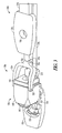
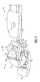
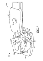
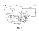
- a low insertion-profile vertebral body replacement (VBR) implant 100 and an associated insertion instrument 200 are provided.
- the implant 100 includes a superior end, an inferior end, and a longitudinal axis therebetween.
- the implant 100 further includes a proximal end engageable with the instrument 200 and a distal end opposite the proximal end.
- the implant 100 includes a superior endplate 110 that is couplable with a central column 120 and the central column 120 further includes an inner strut member 130 and an outer strut member 140.
- the inner strut member 130 is disposed in the interior of the outer strut member 140.
- the superior endplate 110 is, in an example, slidably lockable to the top surface of the inner strut member 130 via the inclusion of, for example, a dovetail and accommodating groove.
- the superior endplate 110 further includes a proximally disposed superior endplate instrument engagement feature 112.
- the superior endplate 110 is pivotably coupled to the central column 120 such that the superior endplate 110 is pivotable into place during insertion of the implant 100.
- the superior endplate 110 includes a locking or engaging feature to maintain the superior endplate 110 in place on the central column 120 once the superior endplate 110 is pivoted into place.
- the inner strut member 130 and the outer strut member 140 are telescopically expandable in height with respect to one another to provide a low insertion height/profile and permit expansion into a final expanded configuration between vertebral bodies.
- the inner strut member 130 is translatable with respect to the outer strut member 140 to thereby provide height expansion to the central column 120 via the inclusion of an expansion mechanism 122.
- the expansion mechanism 122 includes a ratcheting expansion mechanism, a threaded expansion mechanism, a rack and pinion expansion mechanism, a stacking shim expansion mechanism, or other expansion mechanism.
- the expansion mechanism 122 includes a pinion 124 operatively coupled to and selectively actuated using the insertion instrument 200.
- the pinion 124 is positionable in engagement with a rack 126 within the inner strut member 130. Actuation of the pinion 124 translates the rack 126 with respect to the pinion 124 and, in turn, telescopically translate the inner strut member 130 with respect to the outer strut member 140. In this way, the expansion mechanism 122 is used to selectively expand the height of the central column 120.
- the expansion mechanism 122 includes a pawl or other feature to inhibit reverse movement of the inner strut member 130 with respect to the outer strut member 140 to inhibit the expanded central column 120 from retracting.
- the inner strut member 130 and the outer strut member 140 may be open ended, such that each assumes a C-shape in cross section.
- the inner strut member 130 and the outer strut member 140 may take-on hollow cylindrical or other tubular forms.
- an inferior endplate 150 is couplable to the inferior proximal end of the outer strut member 140 via a claw-like first outer strut hinge coupling 146 and a claw-like second outer strut hinge coupling 147 that combine with a pin-like feature or a pair of pin-like features (not shown) on the inferior endplate 150 to form an inferior endplate hinge 154 that enables the central column 120 to rotate with respect to the inferior endplate 150 between an insertion configuration and a load bearing configuration.
- the central column 120 rotates through approximately ninety degrees with respect to the inferior endplate 150 between the insertion configuration and the load bearing configuration.
- the central column 120 rotates through greater than or less than ninety degrees with respect to the inferior endplate 150 between the insertion configuration and the load bearing configuration, depending upon various factors including, for instance, the location for the implant 100 relative to the access channel, or the angular orientation of the final configuration of the implant 100 with respect to the access channel.
- the height of the implant 100 in the load-bearing configuration is greater than the height of the implant 100 in the insertion configuration.
- a variety of other mechanisms can be utilized to form the inferior endplate hinge 154 in addition to the claw-like first and second outer strut hinge couplings 146, 147 and the pin-feature on the inferior endplate 150.
- the central column can include two or more segments pivotably coupled to one another, such that a first segment is pivotably coupled to the inferior endplate 150 and a second segment is pivotably coupled to the first segment and so on. In this way, the first segment can be pivoted into place with respect to the inferior endplate 150 and then each additional segment can be pivoted into place in series thereafter to erect the central column.
- the length of each segment of the central column can be selected and determined by the amount of access space available.
- the two or more segments are each lockable into place.
- the outer strut member 140 includes a first outer strut instrument engagement feature 141 and a second outer strut instrument engagement feature (not shown) disposed on opposite distal superior ends of the outer strut member 140 in its load-bearing configuration.
- the outer strut member 140 further includes a third outer strut instrument engagement feature 143 and a fourth outer strut instrument engagement feature 144 disposed on opposite proximal superior ends of the outer strut member 140 in its load-bearing configuration.
- the inferior distal surface of the outer strut member 140 further includes an optional first snap lock feature 145 that is configured to mate with a corresponding optional second snap-lock feature 155 on the superior surface of the inferior endplate 150 to retain the central column 120 securely with respect to the inferior endplate 150 in the load bearing configuration.
- the inferior endplate 150 further includes a proximally disposed inferior endplate engagement feature 152.
- the superior surface of the superior endplate 110 is configured to contact the inferior endplate of a superior vertebral body and the inferior surface of the inferior endplate 150 is configured to contact the superior endplate of an inferior vertebral body.
- the superior and inferior endplates 110, 150 may include teeth, serrations, ridges, or other anti-repulsion features to secure the endplates 110, 150 to the vertebral bodies in the implanted position.
- the superior and inferior endplates 110, 150 may be formed in a variety of modular geometries, including circular, ovular, kidney bean-shaped, etc., to conform ideally to the endplates of the adjacent vertebral bodies.
- the superior and inferior endplates 110, 150 may further be flat, tapered, concave, or convex to further accommodate the anatomy of the adjacent vertebral endplates.
- the superior and inferior endplates 110, 150 may further include brachytherapy seeds for treating tumors or may be coated or surface treated with beneficial agents.
- the superior and inferior endplates 110, 150 may formed from rigid biocompatible material, such as titanium, stainless steel, or polymers such as PEEK. Alternately, the superior and inferior endplates 110, 150 can be formed from semi-rigid material to enable the superior and inferior endplates 110, 150 to conform to the anatomy of the adjacent vertebral endplates via a force-fit in the implanted position.
- an optional axial bore 160 Disposed through the center of the implant 100 along the longitudinal axis is an optional axial bore 160 configured to house graft material or allow boney through-growth to enable fusion to occur through the implant 100.
- the insertion instrument 200 includes a proximal end and a distal end and a longitudinal axis extending therebetween.
- the instrument 200 includes a first sliding arm 210, a second sliding arm 220, and a third sliding arm 230, wherein the first and second sliding arms 210, 220 are slidably translatable with respect to one another along the longitudinal axis and the second and third sliding arms 220, 230 are slidably translatable with respect to one another along the longitudinal axis.
- the first sliding arm 210 includes a distally disposed engagement feature (not shown) that is couplable to the superior endplate engagement feature 112.
- the second sliding arm 220 includes a distally disposed first forked grasping member 221 that is hingedly coupled to the second sliding arm 220 via a second sliding arm hinge 222.
- the first forked grasping member 221 further includes a first fork arm 223 and a second fork arm 224, wherein the first fork arm 223 and the second fork arm 224 each include protrusions or other features (not shown) that are hingedly mateable with the first outer strut instrument engagement feature 141 and the second outer strut instrument engagement feature (not shown), respectively, to form a first fork arm hinge 225 and a second fork arm hinge 226, respectively.
- the third sliding arm 230 terminates distally in a non-hingedly coupled second forked grasping member 231.
- the second forked grasping member 231 further includes a second fork first arm 233 and a second fork second arm 234, wherein the second fork first arm 233 and the second fork second arm 234 each include protrusions or other features (not shown) that are hingedly mateable with the third outer strut instrument engagement feature 143 and the fourth outer strut instrument engagement feature 144, respectively, to form a second fork first arm hinge 235 and a second fork second arm hinge (not shown), respectively.
- a second forked grasping member base hinge 237 that hingedly couples to the base portion of an extending fork member (not shown) that splits into an extending fork member first arm 239 and an extending fork member second arm 240.
- the extending fork member first arm 239 and the extending fork member second arm 240 include protrusions or other features (not shown) that are hingedly mateable with the inferior endplate engagement feature 152 to form an extending fork member hinge 241.
- the extending fork member (not shown) may not include arms but, rather, can hingedly couple to the inferior endplate engagement feature 152 in any of a variety of other ways as would be apparent to one having ordinary skill in the art.
- the example insertion instrument 200 shown in FIG. 15 includes depictions of features, as described below, which are not shown in FIGS. 2-13 , although it is contemplated that such features can be used with the insertion instrument 200 shown in FIGS. 2-13 .
- the insertion instrument 200 is used with a tunnel 250.
- the tunnel 250 is configured to be inserted within an access channel and provides space for insertion of the implant 100 and for insertion, withdrawal, and operation of the insertion instrument 200 while at the same time providing at least some protection of the body tissue in the area of the access channel from being scraped, pinched, or otherwise contacted by the implant 100 and/or the insertion instrument 200.
- the insertion instrument 200 in an example, includes a handle 260 and an actuator 262.
- the handle 260 is shaped substantially like a pistol grip and the actuator 262 is shaped substantially like a trigger.
- the actuator 262 is coupled to the first and second sliding arms 210, 220 to move the first and second sliding arms 210, 220, as described herein, during insertion of the implant 100.
- the insertion instrument 200 includes a rod 270 disposed within a channel in the insertion instrument 200 and coupled to the pinion 124 of the expansion mechanism 122.
- the pinion 124 is integrally attached to the rod 270.
- the pinion 124 forms a distal end of the rod 270.
- the rod 270 can be the shaft of a separate tool, can include an engagement feature to be matingly engaged with a separate tool, or can include a grip for manual rotation of the rod 270.
- a surgeon provides an access channel to the spine and a portion of a damaged or diseased vertebral body in need of replacement is removed.
- the implant 100 in the insertion configuration ( FIGS. 1 and 2 ), is engaged to the insertion instrument 200, as shown in FIGS.
- the instrument 200 is manipulated to force the implant 100 into the load bearing configuration, as shown in FIGS. 4-7 , by advancing the second sliding arm 220 distally with respect to the third sliding arm 230, thereby causing the second sliding arm hinge 222, the first fork arm hinge 225, the second fork arm hinge 226, the second fork first arm hinge 235, the second fork second arm hinge 236, the second forked grasping member base hinge 237, and the extending fork member hinge 241 to articulate and cause the central column 120 to rotate from the insertion configuration to the load bearing configuration and further cause the engagement of the first snap lock feature 145 with the second snap lock feature 155. As shown in FIGS.
- the first sliding arm 210 is then coupled to the superior endplate 110 via the superior endplate engagement feature 112 and the first sliding arm 210 is coupled to the second sliding arm 220.
- the first sliding arm 210 and the distally coupled superior endplate 110 are advanced distally with respect to the second sliding arm 220, causing the superior endplate 110 to engage and couple to the superior surface of the inner strut member 130.
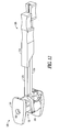
- the first sliding arm 210 is then advanced proximally with respect to the second sliding arm 220, thereby uncoupling the first sliding arm 210 from the superior endplate 110, as shown in FIGS. 10 and 11 .
- the superior endplate 110 is pivotably coupled to the central column 120 to pivot into position with rotation of the central column 120 with respect to the inferior endplate 150, in a manner similar to that described in more detail below.
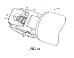
- the implant 100 is then expanded to a desired height, as shown in FIGS. 12 and 14 , by actuating the expansion mechanism 122.
- a number of different methods are envisioned as suitable for imparting force to the necessary elements to cause the inner strut member 130 to advance with respect to the outer strut member 140, depending in part upon the expansion mechanism chosen to characterize the implant 100.
- a distracting force can be imparted to the superior and inferior endplates 110, 150 or to the inner strut member 130 by the insertion instrument 200 itself.
- a separate simple expansion instrument can be coupled over the second and/or third sliding arms 220, 230 and impart the necessary force to the necessary elements of the implant 100 to cause height expansion.
- the separate simple expansion instrument can be coupled to the implant 100 after the instrument 200 is disengaged from the implant 100. Once the desired height has been achieved, the instrument 200 is uncoupled from the implant 100 and the access channel is sealed and the wound covered.
- the implant 100 is not expandable in height via an expansion mechanism, but, rather, is simply characterized by the low profile insertion configuration and the taller load bearing configuration.
- the desired height of the implant can be tailored by choosing, in part, from a range of different superior endplate heights.
- the desired height of the implant can be tailored by choosing, in part, from a range of different strut members with varying heights.
- the inner and outer strut members 130, 140 may be fixed in orientation relative to the superior and inferior endplates 110, 150 and expand longitudinally in a similar manner to a car jack, as opposed to expanding pivotably and longitudinally, as is described in various examples above. It is understood, therefore, that this invention is not limited to the particular examples disclosed, but it is intended to cover modifications within the scope of the present invention as defined by the present description.
- a low insertion-profile VBR implant 300 is shown.
- An associated insertion device although not shown for ease of illustration, is used with the implant 300 and is substantially similar to the insertion device 200 described above.
- the insertion device used with the implant 300 differs from the insertion device 200 described above in that it lacks the structure required to slide the superior endplate into position, for reasons that should become apparent from the description of the implant 300 below.
- the implant 300 can include one or more features and/or one or more properties similar to those included with the implant examples discussed above.
- the implant 300 in an example, includes an inferior endplate 350.
- a central column 320 is pivotably coupled to the inferior endplate 350.
- the central column 320 includes an inner strut member 330 telescopically coupled with an outer strut member 340.
- the inner strut member 330 is telescopically disposed within the outer strut member 340.
- the inner strut member 330 and the outer strut member 340 in an example, are telescopically expandable in height with respect to one another to provide a low insertion height/profile and permit expansion into a final expanded configuration between vertebral bodies.
- the inner strut member 330 is translatable with respect to the outer strut member 340 to thereby provide height expansion to the central column 320 via the inclusion of an expansion mechanism.
- the expansion mechanism includes a ratcheting expansion mechanism, a threaded expansion mechanism, a rack and pinion expansion mechanism, a stacking shim expansion mechanism, or other expansion mechanism.
- the implant 300 includes a superior endplate 310 pivotably engaged with the central column 320.
- the inner strut member 330 includes a first snap lock feature 335 that is configured to mate with a corresponding second snap-lock feature on the inferior surface of the superior endplate 310 to retain the superior endplate 310 securely in a load bearing configuration with respect to the central column 320.
- the implant 300 is inserted similarly to the insertion of the implant 100 described above.
- the superior endplate 310 pivots into place with the pivoting of the central column 320.
- the insertion device is configured to pivot the superior endplate 310 into position.
- the superior endplate 310 is pivoted into place with the pivoting of the central column 320 and sliding contact of the superior endplate 310 with an inferior endplate of a superior vertebral body against which the superior endplate 310 is intended to bear in the load bearing configuration.
- a low insertion-profile VBR implant 400 is shown.
- An associated insertion device although not shown for ease of illustration, is used with the implant 400 and is substantially similar to the insertion device 200 described above. It is noted that, in various examples, in addition to the features and properties described below, the implant 400 can include one or more features and/or one or more properties similar to those included with the implant examples discussed above.
- the implant 400 in an example, includes an inferior endplate 450.
- a central column 420 is pivotably coupled to the inferior endplate 450.
- the central column 420 includes two or more pivoting segments.
- the central column 420 includes first, second, and third pivoting segments 440A, 440B, 440C, with the first pivoting segment 440A pivotably coupled to the inferior endplate 450, the second pivoting segment 440B pivotably coupled to the first pivoting segment 440A, and the third pivoting segment 440C pivotably coupled to the second pivoting segment 440B.
- the implant 400 includes an inner strut member 430 telescopically coupled with the third pivoting segment 440C.
- the inner strut member 430 is telescopically disposed within the third pivoting segment 440C. As shown in FIG. 17C , the inner strut member 430 and the third pivoting segment 440C, in an example, are telescopically expandable in height with respect to one another to provide a low insertion height/profile and permit expansion into a final expanded configuration between vertebral bodies. In various examples, the inner strut member 430 is translatable with respect to the third pivoting segment 440C to thereby provide height expansion to the central column 420 via the inclusion of an expansion mechanism.
- the expansion mechanism includes a ratcheting expansion mechanism, a threaded expansion mechanism, a rack and pinion expansion mechanism, a stacking shim expansion mechanism, or other expansion mechanism.
- the implant can include more or fewer than three segments, depending upon the final desired height of the implant, the size of the access channel, etc.
- the segments of the implant can be preassembled.
- the segments of the implant can be assembled at the time of surgery to enable customization of the implant, for instance, based on the location for the implant, the size and shape of the access channel, and various other conditions present at the time of surgery.
- the implant 400 includes a superior endplate 410 slidably engageable with the central column 420 in a manner similar to that described above with respect to the implant 100.
- the superior endplate 410 is pivotably engaged with the central column 420 in a manner similar to that described above with respect to the implant 300.
- the implant 400 is inserted similarly to the insertion of the implant 100 described above.
- the associated insertion device is configured to pivot all of the segments of the central column 420 into a substantially aligned load-bearing position, as shown in FIG. 17C .
- the expansion mechanism can be actuated to increase the height of the central column 420 to a desired final height to bear against an inferior endplate of a superior vertebral body against which the superior endplate 410 is intended to bear in the load bearing configuration.
Landscapes
- Health & Medical Sciences (AREA)
- Engineering & Computer Science (AREA)
- Biomedical Technology (AREA)
- Orthopedic Medicine & Surgery (AREA)
- Neurology (AREA)
- Transplantation (AREA)
- Oral & Maxillofacial Surgery (AREA)
- Cardiology (AREA)
- Heart & Thoracic Surgery (AREA)
- Vascular Medicine (AREA)
- Life Sciences & Earth Sciences (AREA)
- Animal Behavior & Ethology (AREA)
- General Health & Medical Sciences (AREA)
- Public Health (AREA)
- Veterinary Medicine (AREA)
- Physical Education & Sports Medicine (AREA)
- Prostheses (AREA)
- Surgical Instruments (AREA)
Claims (15)
- Implantierbare Vorrichtung (100; 300; 400), die eingerichtet ist, zwischen einen ersten Wirbelkörper und einen zweiten Wirbelkörper eingeführt zu werden, wobei die implantierbare Vorrichtung (100; 300; 400) umfasst:eine erste Endplatte (150; 350; 450), die eine obere Oberfläche und eine untere Oberfläche aufweist, wobei die untere Oberfläche eingerichtet ist, eine obere Endplatte des ersten Wirbelkörpers zu kontaktieren,ein zentrales Element (120; 320; 420), das schwenkbar an die erste Endplatte (150; 350; 450) gekoppelt ist, wobei das zentrale Element (120; 320; 420) ein erstes Kopplungsmerkmal enthält, undeine zweite Endplatte (110; 310; 410), die eine obere Oberfläche und eine untere Oberfläche aufweist, wobei die obere Oberfläche eingerichtet ist, eine untere Endplatte des zweiten Wirbelkörpers zu kontaktieren, wobei die zweite Endplatte (110; 310; 410) ein zweites Kopplungsmerkmal enthält, das eingerichtet ist, mit dem ersten Kopplungsmerkmal des zentralen Elements zusammenzuwirken,wobei die implantierbare Vorrichtung (100; 300; 400) eine erste Einführkonfiguration und eine zweite lasttragende Konfiguration enthält, wobei die erste Einführkonfiguration das zentrale Element (120; 320; 420) in einer ersten winklige Position bezüglich der ersten Endplatte (150; 350; 450) enthält, wobei die zweite lasttragende Konfiguration das zentrale Element (120; 320; 420) in einer zweiten winkligen Position bezüglich der ersten Endplatte (150; 350; 450) und der zweiten Endplatte (110; 310; 410) enthält, in einer lasttragenden Position, in der das erste Kopplungsmerkmal des zentralen Elements (120; 320; 420) mit dem zweiten Kopplungsmerkmal der zweiten Endplatte zusammenwirkt,dadurch gekennzeichnet, dass das zentrale Element (120; 320; 420) in der zweiten winkligen Position verriegelbar ist, wobei das zentrale Element (120; 320; 420) in der zweiten winkligen Position ist, mit der implantierbaren Vorrichtung (100; 300; 400) in der zweiten lasttragenden Konfiguration.
- Implantierbare Vorrichtung nach Anspruch 1, wobei das zentrale Element (120; 320; 420) von der ersten winkligen Position um im Wesentlichen 90 Grad bezüglich der ersten Endplatte (150; 350; 450) in die zweite winklige Position schwenkbar ist.
- Implantierbare Vorrichtung nach Anspruch 1 oder 2, wobei das zweite Kopplungsmerkmal der zweiten Endplatte (110; 410) eingerichtet ist, gleitend mit dem ersten Kopplungsmerkmal des zentralen Elements (120; 420) zusammenzuwirken.
- Implantierbare Vorrichtung nach einem der Ansprüche 1 bis 3, wobei das zweite Kopplungsmerkmal der zweiten Endplatte (310) schwenkbar mit dem ersten Kopplungsmerkmal des zentralen Elements (320) zusammenwirkt.
- Implantierbare Vorrichtung nach einem der Ansprüche 1 bis 4, wobei eine Höhe der implantierbaren Vorrichtung (100; 300; 400) in der ersten Einführkonfiguration geringer ist als eine Höhe der implantierbaren Vorrichtung (100; 300; 400) in der zweiten lasttragenden Konfiguration.
- Implantierbare Vorrichtung nach einem der Ansprüche 1 bis 5, wobei das zentrale Element (120) ein inneres Strebenelement (130) und ein äußeres Strebenelement (140) enthält, wobei das innere Strebenelement (130) bezüglich des äußeren Strebenelements (140) teleskopisch bewegbar ist.
- Implantierbare Vorrichtung nach Anspruch 6, umfassend einen Ausdehnungsmechanismus (122), der eingerichtet ist, das innere Strebenelement (130) bezüglich des äußeren Strebenelements (140) teleskopisch zu bewegen.
- Implantierbare Vorrichtung nach einem der Ansprüche 1 bis 7, wobei das zentrale Element (420) zumindest ein erstes und zweites Schwenksegment (440A, 440B, 440C) enthält, wobei das erste Schwenksegment (440A) bezüglich der ersten Endplatte (450) schwenkbar ist und das zweite Schwenksegment (440B) bezüglich des ersten Schwenksegments (440A) schwenkbar ist.
- Implantierbare Vorrichtung nach einem der Ansprüche 1 bis 8, wobei das zentrale Element (120; 320; 420) nahe einer proximalen Seite der oberen Oberfläche der ersten Endplatte (150; 350; 450) schwenkbar gekoppelt ist.
- Implantierbare Vorrichtung nach einem der Ansprüche 1 bis 9, wobei die implantierbare Vorrichtung (100; 300; 400) eingerichtet ist, lösbar mit einem Einführinstrument (200) zusammenzuwirken, wobei das Einführinstrument (200) eingerichtet ist, die implantierbare Vorrichtung (100; 300; 400) in der ersten Einführkonfiguration zwischen die obere Endplatte des ersten Wirbelkörpers und die untere Endplatte des zweiten Wirbelkörpers vorzuschieben, wobei das Einführinstrument (200) betätigbar ist, um die implantierbare Vorrichtung (100; 300; 400) in die zweite lasttragende Konfiguration zu bringen.
- System, umfassend:eine implantierbare Vorrichtung (100; 300; 400) nach einem der Ansprüche 1 bis 10, die eingerichtet ist, zwischen einen ersten Wirbelkörper und einen zweiten Wirbelkörper eingeführt zu werden, undein Einführinstrument (200), das entfernbar an die implantierbare Vorrichtung (100; 300; 400) gekoppelt ist, wobei das Einführinstrument (200) eingerichtet ist, die implantierbare Vorrichtung (100; 300; 400) in der ersten Einführkonfiguration zwischen die obere Endplatte des ersten Wirbelkörpers und die untere Endplatte des zweiten Wirbelkörpers vorzuschieben, wobei das Einführinstrument (200) betätigbar ist, um die implantierbare Vorrichtung (100; 300; 400) in die zweite lasttragende Konfiguration zu bringen, wobei das zentrale Element (120; 320; 420) von der ersten winkligen Position in die zweite winklige Position bezüglich der ersten Endplatte (150; 350; 450) und der zweiten Endplatte (110; 310; 410) geschwenkt wird, um sich bezüglich des zentralen Elements (120; 320; 420) in eine lasttragende Position zu bewegen, wobei das erste Kopplungsmerkmal des zentralen Elements (120; 320; 420) mit dem zweiten Kopplungsmerkmal der zweiten Endplatte (110; 310; 410) zusammenwirkt.
- System nach Anspruch 11, umfassend die implantierbare Vorrichtung (100) nach Anspruch 7, wobei der Ausdehnungsmechanismus (122) einen Zahnstangenantrieb (124, 126) umfasst.
- System nach Anspruch 11 oder 12, wobei das Einführinstrument (200) an die zweite Endplatte (110; 410) koppelbar ist, wobei das Einführinstrument (200) eingerichtet ist, die zweite Endplatte (110; 410) gleitend in Eingriff mit dem ersten Kopplungsmerkmal des zentralen Elements (120; 420) vorzuschieben.
- System nach einem der Ansprüche 11 bis 13, wobei das Einführinstrument (200) einen ersten Gleitarm (210) und einen zweiten Gleitarm (220) enthält, wobei der zweite Gleitarm (220) eingerichtet ist, zu gleiten, um das zentrale Element (120) bezüglich der ersten Endplatte (150) zu schwenken, und der erste Gleitarm (210) eingerichtet ist, zu gleiten, um das erste Kopplungsmerkmal des zentralen Elements (120) mit dem zweiten Kopplungsmerkmal der zweiten Endplatte (110) in Eingriff zu bringen.
- System nach Anspruch 14, wobei das Einführinstrument (220) einen dritten Gleitarm (230) enthält, wobei der zweite Gleitarm (220) bezüglich des dritten Gleitarms (230) gleitbar ist, um das zentrale Element (120) bezüglich der ersten Endplatte (150) zu schwenken, und der erste Gleitarm (210) bezüglich des zweiten Gleitarms (220) gleitbar ist, um das erste Kopplungsmerkmal des zentralen Elements mit dem zweiten Kopplungsmerkmal der zweiten Endplatte (110) in Eingriff zu bringen.
Applications Claiming Priority (2)
| Application Number | Priority Date | Filing Date | Title |
|---|---|---|---|
| US13993708P | 2008-12-22 | 2008-12-22 | |
| PCT/US2009/006316 WO2010074700A1 (en) | 2008-12-22 | 2009-12-01 | Expandable vertebral body replacement system and method |
Publications (2)
| Publication Number | Publication Date |
|---|---|
| EP2376026A1 EP2376026A1 (de) | 2011-10-19 |
| EP2376026B1 true EP2376026B1 (de) | 2014-04-23 |
Family
ID=42035276
Family Applications (1)
| Application Number | Title | Priority Date | Filing Date |
|---|---|---|---|
| EP09768260.3A Active EP2376026B1 (de) | 2008-12-22 | 2009-12-01 | Expandierbares wirbelkörper-ersatzsystem |
Country Status (8)
| Country | Link |
|---|---|
| US (2) | US9119725B2 (de) |
| EP (1) | EP2376026B1 (de) |
| JP (1) | JP5650128B2 (de) |
| KR (1) | KR101597857B1 (de) |
| CN (1) | CN102256569B (de) |
| BR (1) | BRPI0921108A2 (de) |
| CA (1) | CA2747599A1 (de) |
| WO (1) | WO2010074700A1 (de) |
Cited By (3)
| Publication number | Priority date | Publication date | Assignee | Title |
|---|---|---|---|---|
| US9216096B2 (en) | 2010-03-16 | 2015-12-22 | Pinnacle Spine Group, Llc | Intervertebral implants and related tools |
| US9380932B1 (en) | 2011-11-02 | 2016-07-05 | Pinnacle Spine Group, Llc | Retractor devices for minimally invasive access to the spine |
| US10070970B2 (en) | 2013-03-14 | 2018-09-11 | Pinnacle Spine Group, Llc | Interbody implants and graft delivery systems |
Families Citing this family (23)
| Publication number | Priority date | Publication date | Assignee | Title |
|---|---|---|---|---|
| US8597360B2 (en) | 2004-11-03 | 2013-12-03 | Neuropro Technologies, Inc. | Bone fusion device |
| JP5650128B2 (ja) | 2008-12-22 | 2015-01-07 | ジンテス ゲゼルシャフト ミット ベシュレンクテル ハフツング | 拡張可能な椎体交換システム及び方法 |
| US8282683B2 (en) * | 2010-04-12 | 2012-10-09 | Globus Medical, Inc. | Expandable vertebral implant |
| US9296637B2 (en) | 2010-06-09 | 2016-03-29 | Glasstech, Inc. | Method for press forming glass sheets |
| DE102010047901B4 (de) * | 2010-10-11 | 2019-01-10 | Heinrich Böhm | Implantat für die Wirbelsäule und Betätigungsinstrument |
| EP2645965B1 (de) * | 2010-11-30 | 2016-08-10 | DePuy Synthes Products, LLC | Käfig zur linderung seitlicher spondylolisthese |
| US9700425B1 (en) | 2011-03-20 | 2017-07-11 | Nuvasive, Inc. | Vertebral body replacement and insertion methods |
| US20140018722A1 (en) | 2011-04-04 | 2014-01-16 | Mis Solutions, Inc. | Apparatus and method for creating a lumen of a desired shape and size in a hollow viscus organ from tissue of the organ |
| US9358123B2 (en) | 2011-08-09 | 2016-06-07 | Neuropro Spinal Jaxx, Inc. | Bone fusion device, apparatus and method |
| WO2013023096A1 (en) | 2011-08-09 | 2013-02-14 | Neuropro Technologies, Inc. | Bone fusion device, system and method |
| US10420654B2 (en) | 2011-08-09 | 2019-09-24 | Neuropro Technologies, Inc. | Bone fusion device, system and method |
| US20130261747A1 (en) * | 2012-03-30 | 2013-10-03 | Christophe Geisert | ALIF Spinal Implant |
| US10159583B2 (en) * | 2012-04-13 | 2018-12-25 | Neuropro Technologies, Inc. | Bone fusion device |
| US9532883B2 (en) | 2012-04-13 | 2017-01-03 | Neuropro Technologies, Inc. | Bone fusion device |
| WO2014144570A2 (en) | 2013-03-15 | 2014-09-18 | Medsmart Innovation, Inc. | Dynamic spinal segment replacement |
| US10098757B2 (en) | 2013-03-15 | 2018-10-16 | Neuropro Technologies Inc. | Bodiless bone fusion device, apparatus and method |
| US10279928B2 (en) * | 2015-08-26 | 2019-05-07 | The Boeing Company | Delta offset based surface modeling |
| EP3228282B1 (de) * | 2016-04-07 | 2023-02-15 | Howmedica Osteonics Corp. | Expandierbares wirbelkörperimplantat |
| US10973657B2 (en) | 2017-01-18 | 2021-04-13 | Neuropro Technologies, Inc. | Bone fusion surgical system and method |
| US10213321B2 (en) | 2017-01-18 | 2019-02-26 | Neuropro Technologies, Inc. | Bone fusion system, device and method including delivery apparatus |
| US10111760B2 (en) * | 2017-01-18 | 2018-10-30 | Neuropro Technologies, Inc. | Bone fusion system, device and method including a measuring mechanism |
| US10729560B2 (en) | 2017-01-18 | 2020-08-04 | Neuropro Technologies, Inc. | Bone fusion system, device and method including an insertion instrument |
| US12589006B2 (en) | 2021-10-08 | 2026-03-31 | Seaspine Orthopedics Corporation | Expandable vertebral implant and method |
Family Cites Families (91)
| Publication number | Priority date | Publication date | Assignee | Title |
|---|---|---|---|---|
| US3785462A (en) * | 1972-06-23 | 1974-01-15 | Applied Radiation Corp | Scissor lift and drive mechanism therefor |
| US5390683A (en) * | 1991-02-22 | 1995-02-21 | Pisharodi; Madhavan | Spinal implantation methods utilizing a middle expandable implant |
| US5193649A (en) * | 1992-06-23 | 1993-03-16 | Steven Lee | Platform car |
| US5782832A (en) | 1996-10-01 | 1998-07-21 | Surgical Dynamics, Inc. | Spinal fusion implant and method of insertion thereof |
| US6190414B1 (en) * | 1996-10-31 | 2001-02-20 | Surgical Dynamics Inc. | Apparatus for fusion of adjacent bone structures |
| US6039761A (en) * | 1997-02-12 | 2000-03-21 | Li Medical Technologies, Inc. | Intervertebral spacer and tool and method for emplacement thereof |
| EP0975288B1 (de) | 1997-04-15 | 2002-10-02 | Synthes AG Chur | Teleskopierende wirbelprothese |
| US6641614B1 (en) * | 1997-05-01 | 2003-11-04 | Spinal Concepts, Inc. | Multi-variable-height fusion device |
| US6045579A (en) * | 1997-05-01 | 2000-04-04 | Spinal Concepts, Inc. | Adjustable height fusion device |
| US6126689A (en) * | 1998-06-15 | 2000-10-03 | Expanding Concepts, L.L.C. | Collapsible and expandable interbody fusion device |
| US6193757B1 (en) * | 1998-10-29 | 2001-02-27 | Sdgi Holdings, Inc. | Expandable intervertebral spacers |
| US6183517B1 (en) * | 1998-12-16 | 2001-02-06 | Loubert Suddaby | Expandable intervertebral fusion implant and applicator |
| US6582451B1 (en) * | 1999-03-16 | 2003-06-24 | The University Of Sydney | Device for use in surgery |
| US6454806B1 (en) * | 1999-07-26 | 2002-09-24 | Advanced Prosthetic Technologies, Inc. | Spinal surgical prosthesis |
| US6224604B1 (en) * | 1999-07-30 | 2001-05-01 | Loubert Suddaby | Expandable orthopedic drill for vertebral interbody fusion techniques |
| DE60201945T2 (de) * | 2001-02-04 | 2005-12-01 | Michelson, Gary Karlin, Los Angeles | Instrument zum Einführen und Spreiten eines Zwischenwirbelfusionsimplantats |
| US6368351B1 (en) * | 2001-03-27 | 2002-04-09 | Bradley J. Glenn | Intervertebral space implant for use in spinal fusion procedures |
| NL1018438C1 (nl) * | 2001-07-02 | 2003-01-08 | Baat Medical Engineering B V | In- en uitklapbaar gereedschap voor plaatsing in een ruggenwervel. |
| DE10138079B4 (de) * | 2001-08-03 | 2004-02-12 | Biedermann Motech Gmbh | Platzhalter mit veränderbarer axialer Länge |
| TW545211U (en) * | 2001-08-29 | 2003-08-01 | Jung-Chiuan Ye | Device for fastening spine |
| US6840944B2 (en) * | 2002-05-21 | 2005-01-11 | Loubert Suddaby | Vertebral body end plate cutter |
| US7070598B2 (en) * | 2002-06-25 | 2006-07-04 | Sdgi Holdings, Inc. | Minimally invasive expanding spacer and method |
| US6981991B2 (en) * | 2002-06-27 | 2006-01-03 | Ferree Bret A | Arthroplasty devices configured to reduce shear stress |
| US6685742B1 (en) * | 2002-11-12 | 2004-02-03 | Roger P. Jackson | Articulated anterior expandable spinal fusion cage system |
| US7828849B2 (en) * | 2003-02-03 | 2010-11-09 | Warsaw Orthopedic, Inc. | Expanding interbody implant and articulating inserter and method |
| KR101129769B1 (ko) | 2003-04-28 | 2012-03-23 | 신세스 게엠바하 | 추간판 임플란트 |
| DE20308171U1 (de) * | 2003-05-21 | 2003-07-31 | Aesculap AG & Co. KG, 78532 Tuttlingen | Wirbelkörperersatzimplantat |
| DE10324319A1 (de) * | 2003-05-27 | 2004-12-16 | Ulrich Gmbh & Co. Kg | Implantat sowie Instrument zur Platzierung und Distraktion des Implantates |
| DE602004023039D1 (de) * | 2003-07-23 | 2009-10-22 | Ebi Llc | Spreizbares Zwischenwirbelimplantat |
| US7753958B2 (en) * | 2003-08-05 | 2010-07-13 | Gordon Charles R | Expandable intervertebral implant |
| US7513900B2 (en) | 2003-09-29 | 2009-04-07 | Boston Scientific Scimed, Inc. | Apparatus and methods for reducing compression bone fractures using high strength ribbed members |
| US7763028B2 (en) * | 2004-02-13 | 2010-07-27 | Warsaw Orthopedic, Inc. | Spacer with height and angle adjustments for spacing vertebral members |
| US7507241B2 (en) | 2004-04-05 | 2009-03-24 | Expanding Orthopedics Inc. | Expandable bone device |
| FR2871366A1 (fr) * | 2004-06-09 | 2005-12-16 | Ceravic Soc Par Actions Simpli | Implant expansible prothetique osseux |
| US7678148B2 (en) * | 2004-07-23 | 2010-03-16 | Warsaw Orthopedic, Inc. | Expandable spinal implant having interlocking geometry for structural support |
| US8317864B2 (en) * | 2004-10-20 | 2012-11-27 | The Board Of Trustees Of The Leland Stanford Junior University | Systems and methods for posterior dynamic stabilization of the spine |
| US8012207B2 (en) * | 2004-10-20 | 2011-09-06 | Vertiflex, Inc. | Systems and methods for posterior dynamic stabilization of the spine |
| US8409282B2 (en) * | 2004-10-20 | 2013-04-02 | Vertiflex, Inc. | Systems and methods for posterior dynamic stabilization of the spine |
| US7887589B2 (en) * | 2004-11-23 | 2011-02-15 | Glenn Bradley J | Minimally invasive spinal disc stabilizer and insertion tool |
| WO2006066228A2 (en) * | 2004-12-16 | 2006-06-22 | Innovative Spinal Technologies | Expandable implants for spinal disc replacement |
| US20060180403A1 (en) * | 2005-01-07 | 2006-08-17 | Hanlon Mark T | Screw scissor lift |
| EP1858457B1 (de) * | 2005-02-24 | 2011-11-02 | Morphogeny, LLC | Verbundene, verschiebbare und zusammensteckbare drehbare komponenten |
| US20100249790A1 (en) * | 2009-03-26 | 2010-09-30 | Martin Roche | System and method for soft tissue tensioning in extension and flexion |
| WO2006105437A2 (en) * | 2005-03-31 | 2006-10-05 | Life Spine, Inc. | Expandable spinal interbody and intravertebral body devices |
| US20060235423A1 (en) * | 2005-04-01 | 2006-10-19 | Cantu Alberto R | Apparatus having at least one actuatable planar surface and method using the same for a spinal procedure |
| DE102005022921B3 (de) | 2005-05-19 | 2007-01-25 | Aesculap Ag & Co. Kg | Wirbelkörperersatzimplantat |
| US8236058B2 (en) * | 2005-09-27 | 2012-08-07 | Fabian Henry F | Spine surgery method and implant |
| US7901409B2 (en) * | 2006-01-20 | 2011-03-08 | Canaveral Villegas Living Trust | Intramedullar devices and methods to reduce and/or fix damaged bone |
| US7828847B2 (en) | 2006-02-15 | 2010-11-09 | Samy Abdou | Devices and methods for inter-vertebral orthopedic device placement |
| GB0605960D0 (en) * | 2006-03-24 | 2006-05-03 | Galley Geoffrey H | Expandable spinal prosthesis |
| DE102006016987B3 (de) * | 2006-04-06 | 2007-10-11 | Aesculap Ag & Co. Kg | Zwischenwirbelimplantat |
| DE102006016985B3 (de) * | 2006-04-06 | 2007-10-11 | Aesculap Ag & Co. Kg | Zwischenwirbelimplantat |
| US7854765B2 (en) * | 2006-04-20 | 2010-12-21 | Moskowitz Mosheh T | Electronically controlled artificial intervertebral disc with motor assisted actuation systems |
| US20070260315A1 (en) * | 2006-05-03 | 2007-11-08 | Foley Kevin T | Devices and methods for disc height restoration |
| EP2032086A4 (de) * | 2006-05-26 | 2013-01-16 | Samy M Abdou | Bandscheibenbewegungsvorrichtungen und anwendungsverfahren |
| US8025697B2 (en) * | 2006-09-21 | 2011-09-27 | Custom Spine, Inc. | Articulating interbody spacer, vertebral body replacement |
| US20080114367A1 (en) * | 2006-11-10 | 2008-05-15 | Syberspine Limited | Method and relaxable distracters for in-situ formation of intervertebral disc prosthesis |
| WO2008121317A1 (en) * | 2007-03-29 | 2008-10-09 | Life Spine, Inc. | Radially expandable spinal interbody device and implantation tool |
| US8137401B2 (en) * | 2007-03-30 | 2012-03-20 | Depuy Spine, Inc. | Intervertebral device having expandable endplates |
| GB0707285D0 (en) * | 2007-04-17 | 2007-05-23 | Burke John | Implantable apparatus for modulation of skeletal growth |
| US8273124B2 (en) * | 2007-05-17 | 2012-09-25 | Depuy Spine, Inc. | Self-distracting cage |
| US8070754B2 (en) * | 2007-05-31 | 2011-12-06 | Fabian Henry F | Spine surgery method and instrumentation |
| US8133232B2 (en) * | 2007-07-17 | 2012-03-13 | Expanding Orthopedics Inc. | Expandable bone device |
| US20090082869A1 (en) * | 2007-09-14 | 2009-03-26 | Slemker Tracy C | Double ended pyramid adapter |
| GB2452923A (en) * | 2007-09-19 | 2009-03-25 | Surgicraft Ltd | Expandable medical device |
| US8147519B2 (en) * | 2007-10-09 | 2012-04-03 | Warsaw Orthopedic, Inc. | Variable angle rod connectors and the methods of use |
| US8241331B2 (en) * | 2007-11-08 | 2012-08-14 | Spine21 Ltd. | Spinal implant having a post-operative adjustable dimension |
| US7799056B2 (en) * | 2007-12-31 | 2010-09-21 | Warsaw Orthopedic, Inc. | Bone fusion device and methods |
| WO2009092030A1 (en) * | 2008-01-16 | 2009-07-23 | Life Spine, Inc. | Spinal inetrbody fusion cages providing variable anterior/posterior profieles |
| US20100145455A1 (en) * | 2008-12-10 | 2010-06-10 | Innvotec Surgical, Inc. | Lockable spinal implant |
| US8696751B2 (en) * | 2008-12-10 | 2014-04-15 | Coalign Innovations, Inc. | Adjustable distraction cage with linked locking mechanisms |
| WO2009120618A2 (en) * | 2008-03-24 | 2009-10-01 | Lanx, Inc. | Expandable spinal interbody cage and methods |
| US8795365B2 (en) * | 2008-03-24 | 2014-08-05 | Warsaw Orthopedic, Inc | Expandable devices for emplacement in body parts and methods associated therewith |
| US20090248092A1 (en) * | 2008-03-26 | 2009-10-01 | Jonathan Bellas | Posterior Intervertebral Disc Inserter and Expansion Techniques |
| US20090270873A1 (en) * | 2008-04-24 | 2009-10-29 | Fabian Henry F | Spine surgery method and inserter |
| US20090299478A1 (en) * | 2008-06-03 | 2009-12-03 | Warsaw Orthopedic, Inc. | Lordotic Implant for Posterior Approach |
| US20100010633A1 (en) * | 2008-07-10 | 2010-01-14 | Kyphon Sarl | Deployable Arc Fusion Cage and Methods Associated Therewith |
| CN102281829A (zh) * | 2008-11-19 | 2011-12-14 | 安杜奥斯皮迪克公司 | 用于骨折的髓内修复系统 |
| JP5650128B2 (ja) | 2008-12-22 | 2015-01-07 | ジンテス ゲゼルシャフト ミット ベシュレンクテル ハフツング | 拡張可能な椎体交換システム及び方法 |
| US8876905B2 (en) * | 2009-04-29 | 2014-11-04 | DePuy Synthes Products, LLC | Minimally invasive corpectomy cage and instrument |
| US9050194B2 (en) * | 2009-05-06 | 2015-06-09 | Stryker Spine | Expandable spinal implant apparatus and method of use |
| US20110001098A1 (en) * | 2009-07-01 | 2011-01-06 | K&L Supply Co., Inc. | Utility jack |
| US8277456B2 (en) * | 2009-07-17 | 2012-10-02 | Ulrich Gmbh & Co. Kg | Spinal-column distractor |
| US8303663B2 (en) * | 2009-07-22 | 2012-11-06 | Spinex Tec, Llc | Methods and apparatuses for vertebral body distraction and fusion employing a coaxial screw gear sleeve mechanism |
| US20110029085A1 (en) * | 2009-07-31 | 2011-02-03 | Warsaw Orthopedic, Inc. | Flexible spinal implant |
| US20110257748A1 (en) * | 2010-04-15 | 2011-10-20 | Jung-Tung Liu | Artificial spinal implant |
| JP5885270B2 (ja) * | 2010-10-05 | 2016-03-15 | ロリオ,モーガン,ピー. | 椎間装置とその使用方法 |
| US20120179258A1 (en) * | 2010-12-28 | 2012-07-12 | Paul Glazer | Spinal spacer devices, tools, and methods |
| US8409291B2 (en) * | 2011-04-07 | 2013-04-02 | Warsaw Orthopedic, Inc. | Laterally expandable interbody spinal fusion implant |
| US8518114B2 (en) * | 2011-04-21 | 2013-08-27 | Warsaw Orthopedic, Inc. | Expandable implant system and methods of use |
| US9427325B2 (en) * | 2013-07-26 | 2016-08-30 | Warsaw Orthopedic, Inc. | Interbody implant and method |
-
2009
- 2009-12-01 JP JP2011542107A patent/JP5650128B2/ja active Active
- 2009-12-01 WO PCT/US2009/006316 patent/WO2010074700A1/en not_active Ceased
- 2009-12-01 CA CA2747599A patent/CA2747599A1/en not_active Abandoned
- 2009-12-01 EP EP09768260.3A patent/EP2376026B1/de active Active
- 2009-12-01 CN CN200980150736.4A patent/CN102256569B/zh active Active
- 2009-12-01 BR BRPI0921108A patent/BRPI0921108A2/pt not_active IP Right Cessation
- 2009-12-01 US US13/141,235 patent/US9119725B2/en not_active Expired - Fee Related
- 2009-12-01 KR KR1020117013805A patent/KR101597857B1/ko active Active
-
2015
- 2015-07-27 US US14/809,904 patent/US9782267B2/en active Active
Cited By (5)
| Publication number | Priority date | Publication date | Assignee | Title |
|---|---|---|---|---|
| US9216096B2 (en) | 2010-03-16 | 2015-12-22 | Pinnacle Spine Group, Llc | Intervertebral implants and related tools |
| US9649203B2 (en) | 2010-03-16 | 2017-05-16 | Pinnacle Spine Group, Llc | Methods of post-filling an intervertebral implant |
| US9788973B2 (en) | 2010-03-16 | 2017-10-17 | Pinnacle Spine Group, Llc | Spinal implant |
| US9380932B1 (en) | 2011-11-02 | 2016-07-05 | Pinnacle Spine Group, Llc | Retractor devices for minimally invasive access to the spine |
| US10070970B2 (en) | 2013-03-14 | 2018-09-11 | Pinnacle Spine Group, Llc | Interbody implants and graft delivery systems |
Also Published As
| Publication number | Publication date |
|---|---|
| US20150328013A1 (en) | 2015-11-19 |
| WO2010074700A1 (en) | 2010-07-01 |
| CA2747599A1 (en) | 2010-07-01 |
| KR101597857B1 (ko) | 2016-02-25 |
| CN102256569A (zh) | 2011-11-23 |
| EP2376026A1 (de) | 2011-10-19 |
| BRPI0921108A2 (pt) | 2016-02-16 |
| JP2012513242A (ja) | 2012-06-14 |
| US20110257750A1 (en) | 2011-10-20 |
| JP5650128B2 (ja) | 2015-01-07 |
| US9782267B2 (en) | 2017-10-10 |
| KR20110096043A (ko) | 2011-08-26 |
| CN102256569B (zh) | 2014-01-22 |
| US9119725B2 (en) | 2015-09-01 |
Similar Documents
| Publication | Publication Date | Title |
|---|---|---|
| US9782267B2 (en) | Expandable vertebral body replacement system and method | |
| US20240268967A1 (en) | Expandable vertebral implant | |
| US20200297507A1 (en) | Expandable vertebral implant | |
| US10299934B2 (en) | Expandable vertebral implant | |
| US10874522B2 (en) | Articulating expandable intervertebral implant | |
| USRE47796E1 (en) | Posterior spinal device and method | |
| US9833336B2 (en) | Expandable intervertebral implant | |
| US9707092B2 (en) | Expandable intervertebral implant | |
| US9655737B2 (en) | Expandable interbody spacer | |
| US9034045B2 (en) | Expandable intervertebral implant | |
| EP3030198B1 (de) | Bewegliches und dehnbares zwischenwirbelimplantat | |
| US20080221694A1 (en) | Pivotable Interbody Spacer System and Method |
Legal Events
| Date | Code | Title | Description |
|---|---|---|---|
| PUAI | Public reference made under article 153(3) epc to a published international application that has entered the european phase |
Free format text: ORIGINAL CODE: 0009012 |
|
| 17P | Request for examination filed |
Effective date: 20110715 |
|
| AK | Designated contracting states |
Kind code of ref document: A1 Designated state(s): AT BE BG CH CY CZ DE DK EE ES FI FR GB GR HR HU IE IS IT LI LT LU LV MC MK MT NL NO PL PT RO SE SI SK SM TR |
|
| DAX | Request for extension of the european patent (deleted) | ||
| 17Q | First examination report despatched |
Effective date: 20130905 |
|
| GRAP | Despatch of communication of intention to grant a patent |
Free format text: ORIGINAL CODE: EPIDOSNIGR1 |
|
| INTG | Intention to grant announced |
Effective date: 20140106 |
|
| GRAS | Grant fee paid |
Free format text: ORIGINAL CODE: EPIDOSNIGR3 |
|
| GRAA | (expected) grant |
Free format text: ORIGINAL CODE: 0009210 |
|
| AK | Designated contracting states |
Kind code of ref document: B1 Designated state(s): AT BE BG CH CY CZ DE DK EE ES FI FR GB GR HR HU IE IS IT LI LT LU LV MC MK MT NL NO PL PT RO SE SI SK SM TR |
|
| REG | Reference to a national code |
Ref country code: GB Ref legal event code: FG4D |
|
| REG | Reference to a national code |
Ref country code: CH Ref legal event code: EP |
|
| REG | Reference to a national code |
Ref country code: AT Ref legal event code: REF Ref document number: 663314 Country of ref document: AT Kind code of ref document: T Effective date: 20140515 |
|
| REG | Reference to a national code |
Ref country code: IE Ref legal event code: FG4D |
|
| REG | Reference to a national code |
Ref country code: DE Ref legal event code: R096 Ref document number: 602009023511 Country of ref document: DE Effective date: 20140605 |
|
| REG | Reference to a national code |
Ref country code: AT Ref legal event code: MK05 Ref document number: 663314 Country of ref document: AT Kind code of ref document: T Effective date: 20140423 |
|
| REG | Reference to a national code |
Ref country code: NL Ref legal event code: VDEP Effective date: 20140423 |
|
| REG | Reference to a national code |
Ref country code: LT Ref legal event code: MG4D |
|
| PG25 | Lapsed in a contracting state [announced via postgrant information from national office to epo] |
Ref country code: BG Free format text: LAPSE BECAUSE OF FAILURE TO SUBMIT A TRANSLATION OF THE DESCRIPTION OR TO PAY THE FEE WITHIN THE PRESCRIBED TIME-LIMIT Effective date: 20140723 Ref country code: CY Free format text: LAPSE BECAUSE OF FAILURE TO SUBMIT A TRANSLATION OF THE DESCRIPTION OR TO PAY THE FEE WITHIN THE PRESCRIBED TIME-LIMIT Effective date: 20140423 Ref country code: NO Free format text: LAPSE BECAUSE OF FAILURE TO SUBMIT A TRANSLATION OF THE DESCRIPTION OR TO PAY THE FEE WITHIN THE PRESCRIBED TIME-LIMIT Effective date: 20140723 Ref country code: GR Free format text: LAPSE BECAUSE OF FAILURE TO SUBMIT A TRANSLATION OF THE DESCRIPTION OR TO PAY THE FEE WITHIN THE PRESCRIBED TIME-LIMIT Effective date: 20140724 Ref country code: FI Free format text: LAPSE BECAUSE OF FAILURE TO SUBMIT A TRANSLATION OF THE DESCRIPTION OR TO PAY THE FEE WITHIN THE PRESCRIBED TIME-LIMIT Effective date: 20140423 Ref country code: IS Free format text: LAPSE BECAUSE OF FAILURE TO SUBMIT A TRANSLATION OF THE DESCRIPTION OR TO PAY THE FEE WITHIN THE PRESCRIBED TIME-LIMIT Effective date: 20140823 Ref country code: LT Free format text: LAPSE BECAUSE OF FAILURE TO SUBMIT A TRANSLATION OF THE DESCRIPTION OR TO PAY THE FEE WITHIN THE PRESCRIBED TIME-LIMIT Effective date: 20140423 Ref country code: NL Free format text: LAPSE BECAUSE OF FAILURE TO SUBMIT A TRANSLATION OF THE DESCRIPTION OR TO PAY THE FEE WITHIN THE PRESCRIBED TIME-LIMIT Effective date: 20140423 |
|
| PG25 | Lapsed in a contracting state [announced via postgrant information from national office to epo] |
Ref country code: PL Free format text: LAPSE BECAUSE OF FAILURE TO SUBMIT A TRANSLATION OF THE DESCRIPTION OR TO PAY THE FEE WITHIN THE PRESCRIBED TIME-LIMIT Effective date: 20140423 Ref country code: SE Free format text: LAPSE BECAUSE OF FAILURE TO SUBMIT A TRANSLATION OF THE DESCRIPTION OR TO PAY THE FEE WITHIN THE PRESCRIBED TIME-LIMIT Effective date: 20140423 Ref country code: LV Free format text: LAPSE BECAUSE OF FAILURE TO SUBMIT A TRANSLATION OF THE DESCRIPTION OR TO PAY THE FEE WITHIN THE PRESCRIBED TIME-LIMIT Effective date: 20140423 Ref country code: AT Free format text: LAPSE BECAUSE OF FAILURE TO SUBMIT A TRANSLATION OF THE DESCRIPTION OR TO PAY THE FEE WITHIN THE PRESCRIBED TIME-LIMIT Effective date: 20140423 Ref country code: HR Free format text: LAPSE BECAUSE OF FAILURE TO SUBMIT A TRANSLATION OF THE DESCRIPTION OR TO PAY THE FEE WITHIN THE PRESCRIBED TIME-LIMIT Effective date: 20140423 Ref country code: ES Free format text: LAPSE BECAUSE OF FAILURE TO SUBMIT A TRANSLATION OF THE DESCRIPTION OR TO PAY THE FEE WITHIN THE PRESCRIBED TIME-LIMIT Effective date: 20140423 |
|
| PG25 | Lapsed in a contracting state [announced via postgrant information from national office to epo] |
Ref country code: PT Free format text: LAPSE BECAUSE OF FAILURE TO SUBMIT A TRANSLATION OF THE DESCRIPTION OR TO PAY THE FEE WITHIN THE PRESCRIBED TIME-LIMIT Effective date: 20140825 |
|
| REG | Reference to a national code |
Ref country code: DE Ref legal event code: R097 Ref document number: 602009023511 Country of ref document: DE |
|
| PG25 | Lapsed in a contracting state [announced via postgrant information from national office to epo] |
Ref country code: SK Free format text: LAPSE BECAUSE OF FAILURE TO SUBMIT A TRANSLATION OF THE DESCRIPTION OR TO PAY THE FEE WITHIN THE PRESCRIBED TIME-LIMIT Effective date: 20140423 Ref country code: BE Free format text: LAPSE BECAUSE OF FAILURE TO SUBMIT A TRANSLATION OF THE DESCRIPTION OR TO PAY THE FEE WITHIN THE PRESCRIBED TIME-LIMIT Effective date: 20140423 Ref country code: CZ Free format text: LAPSE BECAUSE OF FAILURE TO SUBMIT A TRANSLATION OF THE DESCRIPTION OR TO PAY THE FEE WITHIN THE PRESCRIBED TIME-LIMIT Effective date: 20140423 Ref country code: DK Free format text: LAPSE BECAUSE OF FAILURE TO SUBMIT A TRANSLATION OF THE DESCRIPTION OR TO PAY THE FEE WITHIN THE PRESCRIBED TIME-LIMIT Effective date: 20140423 Ref country code: EE Free format text: LAPSE BECAUSE OF FAILURE TO SUBMIT A TRANSLATION OF THE DESCRIPTION OR TO PAY THE FEE WITHIN THE PRESCRIBED TIME-LIMIT Effective date: 20140423 Ref country code: RO Free format text: LAPSE BECAUSE OF FAILURE TO SUBMIT A TRANSLATION OF THE DESCRIPTION OR TO PAY THE FEE WITHIN THE PRESCRIBED TIME-LIMIT Effective date: 20140423 |
|
| PLBE | No opposition filed within time limit |
Free format text: ORIGINAL CODE: 0009261 |
|
| STAA | Information on the status of an ep patent application or granted ep patent |
Free format text: STATUS: NO OPPOSITION FILED WITHIN TIME LIMIT |
|
| PG25 | Lapsed in a contracting state [announced via postgrant information from national office to epo] |
Ref country code: IT Free format text: LAPSE BECAUSE OF FAILURE TO SUBMIT A TRANSLATION OF THE DESCRIPTION OR TO PAY THE FEE WITHIN THE PRESCRIBED TIME-LIMIT Effective date: 20140423 |
|
| 26N | No opposition filed |
Effective date: 20150126 |
|
| REG | Reference to a national code |
Ref country code: DE Ref legal event code: R097 Ref document number: 602009023511 Country of ref document: DE Effective date: 20150126 |
|
| PG25 | Lapsed in a contracting state [announced via postgrant information from national office to epo] |
Ref country code: SI Free format text: LAPSE BECAUSE OF FAILURE TO SUBMIT A TRANSLATION OF THE DESCRIPTION OR TO PAY THE FEE WITHIN THE PRESCRIBED TIME-LIMIT Effective date: 20140423 Ref country code: LU Free format text: LAPSE BECAUSE OF FAILURE TO SUBMIT A TRANSLATION OF THE DESCRIPTION OR TO PAY THE FEE WITHIN THE PRESCRIBED TIME-LIMIT Effective date: 20141201 |
|
| REG | Reference to a national code |
Ref country code: CH Ref legal event code: PL |
|
| REG | Reference to a national code |
Ref country code: IE Ref legal event code: MM4A |
|
| REG | Reference to a national code |
Ref country code: FR Ref legal event code: ST Effective date: 20150831 |
|
| PG25 | Lapsed in a contracting state [announced via postgrant information from national office to epo] |
Ref country code: LI Free format text: LAPSE BECAUSE OF NON-PAYMENT OF DUE FEES Effective date: 20141231 Ref country code: CH Free format text: LAPSE BECAUSE OF NON-PAYMENT OF DUE FEES Effective date: 20141231 Ref country code: IE Free format text: LAPSE BECAUSE OF NON-PAYMENT OF DUE FEES Effective date: 20141201 |
|
| PG25 | Lapsed in a contracting state [announced via postgrant information from national office to epo] |
Ref country code: FR Free format text: LAPSE BECAUSE OF NON-PAYMENT OF DUE FEES Effective date: 20141231 |
|
| PG25 | Lapsed in a contracting state [announced via postgrant information from national office to epo] |
Ref country code: SM Free format text: LAPSE BECAUSE OF FAILURE TO SUBMIT A TRANSLATION OF THE DESCRIPTION OR TO PAY THE FEE WITHIN THE PRESCRIBED TIME-LIMIT Effective date: 20140423 |
|
| PG25 | Lapsed in a contracting state [announced via postgrant information from national office to epo] |
Ref country code: MC Free format text: LAPSE BECAUSE OF FAILURE TO SUBMIT A TRANSLATION OF THE DESCRIPTION OR TO PAY THE FEE WITHIN THE PRESCRIBED TIME-LIMIT Effective date: 20140423 |
|
| PG25 | Lapsed in a contracting state [announced via postgrant information from national office to epo] |
Ref country code: TR Free format text: LAPSE BECAUSE OF FAILURE TO SUBMIT A TRANSLATION OF THE DESCRIPTION OR TO PAY THE FEE WITHIN THE PRESCRIBED TIME-LIMIT Effective date: 20140423 Ref country code: HU Free format text: LAPSE BECAUSE OF FAILURE TO SUBMIT A TRANSLATION OF THE DESCRIPTION OR TO PAY THE FEE WITHIN THE PRESCRIBED TIME-LIMIT; INVALID AB INITIO Effective date: 20091201 Ref country code: MT Free format text: LAPSE BECAUSE OF FAILURE TO SUBMIT A TRANSLATION OF THE DESCRIPTION OR TO PAY THE FEE WITHIN THE PRESCRIBED TIME-LIMIT Effective date: 20140423 |
|
| REG | Reference to a national code |
Ref country code: DE Ref legal event code: R082 Ref document number: 602009023511 Country of ref document: DE Representative=s name: KLUNKER IP PATENTANWAELTE PARTG MBB, DE |
|
| PG25 | Lapsed in a contracting state [announced via postgrant information from national office to epo] |
Ref country code: MK Free format text: LAPSE BECAUSE OF FAILURE TO SUBMIT A TRANSLATION OF THE DESCRIPTION OR TO PAY THE FEE WITHIN THE PRESCRIBED TIME-LIMIT Effective date: 20140423 |
|
| PGFP | Annual fee paid to national office [announced via postgrant information from national office to epo] |
Ref country code: DE Payment date: 20220622 Year of fee payment: 14 |
|
| REG | Reference to a national code |
Ref country code: DE Ref legal event code: R119 Ref document number: 602009023511 Country of ref document: DE |
|
| PG25 | Lapsed in a contracting state [announced via postgrant information from national office to epo] |
Ref country code: DE Free format text: LAPSE BECAUSE OF NON-PAYMENT OF DUE FEES Effective date: 20240702 |
|
| PG25 | Lapsed in a contracting state [announced via postgrant information from national office to epo] |
Ref country code: DE Free format text: LAPSE BECAUSE OF NON-PAYMENT OF DUE FEES Effective date: 20240702 |
|
| PGFP | Annual fee paid to national office [announced via postgrant information from national office to epo] |
Ref country code: GB Payment date: 20251030 Year of fee payment: 17 |