EP2376236B1 - Pulverzuführbehälter mit einer beruhigten zone, ein pulverzuführbehälter in kombination mit einer sprühpistole und eine methode um einen pulverzuführbehälter zu betreiben - Google Patents
Pulverzuführbehälter mit einer beruhigten zone, ein pulverzuführbehälter in kombination mit einer sprühpistole und eine methode um einen pulverzuführbehälter zu betreiben Download PDFInfo
- Publication number
- EP2376236B1 EP2376236B1 EP09795861.5A EP09795861A EP2376236B1 EP 2376236 B1 EP2376236 B1 EP 2376236B1 EP 09795861 A EP09795861 A EP 09795861A EP 2376236 B1 EP2376236 B1 EP 2376236B1
- Authority
- EP
- European Patent Office
- Prior art keywords
- powder
- hopper
- nozzle
- baffle
- spray gun
- Prior art date
- Legal status (The legal status is an assumption and is not a legal conclusion. Google has not performed a legal analysis and makes no representation as to the accuracy of the status listed.)
- Revoked
Links
Images





Classifications
-
- B—PERFORMING OPERATIONS; TRANSPORTING
- B05—SPRAYING OR ATOMISING IN GENERAL; APPLYING FLUENT MATERIALS TO SURFACES, IN GENERAL
- B05D—PROCESSES FOR APPLYING FLUENT MATERIALS TO SURFACES, IN GENERAL
- B05D1/00—Processes for applying liquids or other fluent materials
- B05D1/02—Processes for applying liquids or other fluent materials performed by spraying
- B05D1/12—Applying particulate materials
-
- B—PERFORMING OPERATIONS; TRANSPORTING
- B05—SPRAYING OR ATOMISING IN GENERAL; APPLYING FLUENT MATERIALS TO SURFACES, IN GENERAL
- B05B—SPRAYING APPARATUS; ATOMISING APPARATUS; NOZZLES
- B05B5/00—Electrostatic spraying apparatus; Spraying apparatus with means for charging the spray electrically; Apparatus for spraying liquids or other fluent materials by other electric means
- B05B5/025—Discharge apparatus, e.g. electrostatic spray guns
- B05B5/03—Discharge apparatus, e.g. electrostatic spray guns characterised by the use of gas, e.g. electrostatically assisted pneumatic spraying
- B05B5/032—Discharge apparatus, e.g. electrostatic spray guns characterised by the use of gas, e.g. electrostatically assisted pneumatic spraying for spraying particulate materials
-
- B—PERFORMING OPERATIONS; TRANSPORTING
- B05—SPRAYING OR ATOMISING IN GENERAL; APPLYING FLUENT MATERIALS TO SURFACES, IN GENERAL
- B05B—SPRAYING APPARATUS; ATOMISING APPARATUS; NOZZLES
- B05B13/00—Machines or plants for applying liquids or other fluent materials to surfaces of objects or other work by spraying, not covered by groups B05B1/00 - B05B11/00
- B05B13/06—Machines or plants for applying liquids or other fluent materials to surfaces of objects or other work by spraying, not covered by groups B05B1/00 - B05B11/00 specially designed for treating the inside of hollow bodies
- B05B13/069—Machines or plants for applying liquids or other fluent materials to surfaces of objects or other work by spraying, not covered by groups B05B1/00 - B05B11/00 specially designed for treating the inside of hollow bodies the hollow bodies having a closed end
-
- B—PERFORMING OPERATIONS; TRANSPORTING
- B05—SPRAYING OR ATOMISING IN GENERAL; APPLYING FLUENT MATERIALS TO SURFACES, IN GENERAL
- B05B—SPRAYING APPARATUS; ATOMISING APPARATUS; NOZZLES
- B05B15/00—Details of spraying plant or spraying apparatus not otherwise provided for; Accessories
- B05B15/20—Arrangements for agitating the material to be sprayed, e.g. for stirring, mixing or homogenising
- B05B15/25—Arrangements for agitating the material to be sprayed, e.g. for stirring, mixing or homogenising using moving elements, e.g. rotating blades
-
- B—PERFORMING OPERATIONS; TRANSPORTING
- B05—SPRAYING OR ATOMISING IN GENERAL; APPLYING FLUENT MATERIALS TO SURFACES, IN GENERAL
- B05B—SPRAYING APPARATUS; ATOMISING APPARATUS; NOZZLES
- B05B7/00—Spraying apparatus for discharge of liquids or other fluent materials from two or more sources, e.g. of liquid and air, of powder and gas
- B05B7/14—Spraying apparatus for discharge of liquids or other fluent materials from two or more sources, e.g. of liquid and air, of powder and gas designed for spraying particulate materials
- B05B7/1404—Arrangements for supplying particulate material
- B05B7/144—Arrangements for supplying particulate material the means for supplying particulate material comprising moving mechanical means
- B05B7/1445—Arrangements for supplying particulate material the means for supplying particulate material comprising moving mechanical means involving vibrations
-
- B—PERFORMING OPERATIONS; TRANSPORTING
- B05—SPRAYING OR ATOMISING IN GENERAL; APPLYING FLUENT MATERIALS TO SURFACES, IN GENERAL
- B05B—SPRAYING APPARATUS; ATOMISING APPARATUS; NOZZLES
- B05B7/00—Spraying apparatus for discharge of liquids or other fluent materials from two or more sources, e.g. of liquid and air, of powder and gas
- B05B7/14—Spraying apparatus for discharge of liquids or other fluent materials from two or more sources, e.g. of liquid and air, of powder and gas designed for spraying particulate materials
- B05B7/1404—Arrangements for supplying particulate material
- B05B7/1463—Arrangements for supplying particulate material the means for supplying particulate material comprising a gas inlet for pressurising or avoiding depressurisation of a powder container
-
- B—PERFORMING OPERATIONS; TRANSPORTING
- B05—SPRAYING OR ATOMISING IN GENERAL; APPLYING FLUENT MATERIALS TO SURFACES, IN GENERAL
- B05B—SPRAYING APPARATUS; ATOMISING APPARATUS; NOZZLES
- B05B7/00—Spraying apparatus for discharge of liquids or other fluent materials from two or more sources, e.g. of liquid and air, of powder and gas
- B05B7/14—Spraying apparatus for discharge of liquids or other fluent materials from two or more sources, e.g. of liquid and air, of powder and gas designed for spraying particulate materials
- B05B7/1404—Arrangements for supplying particulate material
- B05B7/1472—Powder extracted from a powder container in a direction substantially opposite to gravity by a suction device dipped into the powder
-
- B—PERFORMING OPERATIONS; TRANSPORTING
- B05—SPRAYING OR ATOMISING IN GENERAL; APPLYING FLUENT MATERIALS TO SURFACES, IN GENERAL
- B05B—SPRAYING APPARATUS; ATOMISING APPARATUS; NOZZLES
- B05B7/00—Spraying apparatus for discharge of liquids or other fluent materials from two or more sources, e.g. of liquid and air, of powder and gas
- B05B7/14—Spraying apparatus for discharge of liquids or other fluent materials from two or more sources, e.g. of liquid and air, of powder and gas designed for spraying particulate materials
- B05B7/1404—Arrangements for supplying particulate material
- B05B7/1477—Arrangements for supplying particulate material means for supplying to several spray apparatus
-
- B—PERFORMING OPERATIONS; TRANSPORTING
- B05—SPRAYING OR ATOMISING IN GENERAL; APPLYING FLUENT MATERIALS TO SURFACES, IN GENERAL
- B05D—PROCESSES FOR APPLYING FLUENT MATERIALS TO SURFACES, IN GENERAL
- B05D1/00—Processes for applying liquids or other fluent materials
- B05D1/02—Processes for applying liquids or other fluent materials performed by spraying
- B05D1/04—Processes for applying liquids or other fluent materials performed by spraying involving the use of an electrostatic field
- B05D1/06—Applying particulate materials
-
- B—PERFORMING OPERATIONS; TRANSPORTING
- B05—SPRAYING OR ATOMISING IN GENERAL; APPLYING FLUENT MATERIALS TO SURFACES, IN GENERAL
- B05B—SPRAYING APPARATUS; ATOMISING APPARATUS; NOZZLES
- B05B1/00—Nozzles, spray heads or other outlets, with or without auxiliary devices such as valves, heating means
- B05B1/14—Nozzles, spray heads or other outlets, with or without auxiliary devices such as valves, heating means with multiple outlet openings; with strainers in or outside the outlet opening
-
- B—PERFORMING OPERATIONS; TRANSPORTING
- B05—SPRAYING OR ATOMISING IN GENERAL; APPLYING FLUENT MATERIALS TO SURFACES, IN GENERAL
- B05B—SPRAYING APPARATUS; ATOMISING APPARATUS; NOZZLES
- B05B13/00—Machines or plants for applying liquids or other fluent materials to surfaces of objects or other work by spraying, not covered by groups B05B1/00 - B05B11/00
- B05B13/06—Machines or plants for applying liquids or other fluent materials to surfaces of objects or other work by spraying, not covered by groups B05B1/00 - B05B11/00 specially designed for treating the inside of hollow bodies
- B05B13/0627—Arrangements of nozzles or spray heads specially adapted for treating the inside of hollow bodies
Definitions
- the present disclosure relates to powder coating systems that use a hopper for supplying or feeding powder to one or more coating application devices and the corresponding method. More particularly, the disclosure relates to powder coating hoppers that produce a fluidized supply of powder, and also separately relates to powder coating equipment that may be used with such hoppers.
- powder coating material is commonly transferred from a bulk supply or supply hopper to a feed hopper, and then a pump is used to convey the powder from the feed hopper to one or more application devices, such as, for example, a spray gun.
- a feed hopper is commonly a fluidized hopper which fluidizes the powder coating material before it is pumped to a spray gun or application device.
- a very fine powder coating material must be used to achieve the desired surface finish or other coating property. While there are various applications in which powder coating equipment suitable for fine powders are useful, one example is a powder coating system for the inside coating of small diameter tube shaped containers.
- EP 0974400 discloses a powder hopper with a fluidized bed and a suspended rectangular baffle which divides the bed in two sections according to the preamble of claim 1.
- the invention provides a hopper for powder coating material comprising a hopper body comprising a cylinder, a cover at an upper end of the hopper body, a fluidizing bed at a lower end of the hopper body, a baffle inside the hopper body and extending towards the fluidizing bed, at least one powder inlet disposed to feed powder into the hopper body, and a powder outlet, characterized in that the baffle comprises a cylinder of smaller diameter than the diameter of the hopper body so as to form an annular region between the hopper body and the baffle, the powder inlet being disposed in the annular region so that the baffle provides a low turbulence zone for fluidized powder as powder is being added to the hopper, the powder outlet being disposed for removing powder from said low turbulence zone.
- the axial length of the baffle is such that a lower gap is provided between the baffle and the fluidizing bed, and an upper gap is provided between the baffle and the cover.
- an optional agitator may be provided near the fluidizing bed in the region of the lower gap, one or more optional venting pumps may be used to keep the hopper at a negative pressure, an optional switch may be used to deactivate an optional air motor when the cover is separated from the hopper body, and one or more pumps may be used to pump fluidized powder from the low turbulence zone to one or more coating material application devices.
- the nozzle may comprise a plurality of discrete flow passages disposed about a longitudinal axis of the nozzle.
- a powder coating material application system may utilize the hopper as set forth above, a coating material application device as set forth above, and the combination thereof.
- Also disclosed is a method for operating a powder supply hopper wherein the method includes the steps of venting air from an internal volume at a higher rate when powder is being added to the volume and at a lower rate to vent fluidizing air from the volume.
- the hopper concepts may be used with many different configurations of the hopper and associated optional components, and from a system standpoint may be used with many different types of coating material application devices, pumps, bulk feed and control systems, all of which are well known or may be later developed.
- the application device and nozzle concepts may be used with many different hopper arrangements, pumps and so on, including the embodiments illustrated herein. While the exemplary embodiments are illustrated and discussed in terms of a coating application system for small diameter tube shaped containers, other container shapes and types may alternatively be coated.
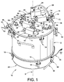
- a hopper 10 is illustrated.
- This hopper 10 may be used for supplying fluidized powder coating material to one or more application devices (see Fig. 5 , for example) and as such may be also referred to herein as a supply hopper.
- the hopper 10 may be used in any use or application it which it is desired to provide fluidized powder coating material to a downstream application or use, including to another hopper to name one example.
- the various parts of the hopper such as the hopper body, cover and the baffle (to be described herein below) may be made of any suitable material such as, for example, stainless steel.
- the hopper 10 includes a hopper body 12 which may be in the form of a right cylinder having an upper end 14 and a lower end 16. Clamps or straps 18 or other suitable attachment means may be used to join a fluidizing drum 20 to the lower end 16 of the hopper body 12.
- a fluidizing subassembly 22 which may include the hopper body 12 and the fluidizing drum 20 is illustrated in greater detail in Figs. 2A, 2B and 3 as described hereinbelow.
- Clamps or straps 24 or other suitable attachment means may be used to join a cover 26 to the upper end 14 of the hopper body 12.
- one or more optional venting pumps 28 may be disposed on the cover 26. These venting pumps 28 may be used to reduce pressure buildup within the hopper 10, and in particular may optionally be used to maintain the hopper 10 interior at a somewhat negative pressure, for example, on the order of less than about 0,10159 bar (three inches mercury) Although two venting pumps 28 are illustrated in Fig.
- venting pumps 28 are shown approximately diametrically opposed each other so as to maintain good pressure balance within the hopper 10.
- Each venting pump 28 may be realized, for example, in the form of a conventional Venturi pump having a pressurized air inlet fitting 30 and an outlet 32.
- the venting pumps 28 will tend to withdraw not only fluidizing and transport air but also some powder, therefore, a hose (not shown) will be connected to the outlet 32 to capture the powder and feed it back to the bulk supply or to waste.
- Air flow may be controlled to the venting pumps inlets 30 so as to control how much air is being vented from the hopper 10, as will be further described herein.
- Venturi-type venting pumps 28 the higher the air flow to the inlets 30, the greater the suction is created to vent air from the hopper 10.
- feed pumps 34 are used to suck fluidized powder from the hopper 10 and pump the powder to one or more application devices (see Fig. 5 ), such as, for example, an automatic or manual powder spray gun.
- the feed pumps 34 illustrated are conventional Venturi type pumps, but other pump designs may be used, including but not limited to dense phase pumps.
- Each pump 34 includes a flow air inlet fitting 36 and an optional fluidizing air inlet fitting 38, as well as an outlet hose connector 40.
- the outlet hose connector 40 receives a feed hose 42 ( Fig. 5 ) so as to pump fluidized powder coating material to an application device (one such use shown in Fig. 5 ), or the feed pumps 34 may optionally be used to transfer the fluidized powder coating material to another downstream use, including another hopper, for example.
- Each feed pump 34 further includes a suction tube connection 44 which connects a suction tube 46 ( Figs. 5 and 9 ).
- Each feed pump 34 operates to create a low pressure zone in the pump body that is in fluid communication with its associated suction tube, so as to suck fluidized powder up into the pump from the hopper 10.
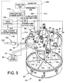
- Flow air 210 ( Fig. 5 ) is used to create this suction and to push the fluidized powder out each pump to its associated application device 202 ( Fig. 5 ) through the feed hose 42.
- an optional air motor driven vibrator 48 is provided, which includes an air fitting 50 to which is connected a pressurized air hose 52. As best illustrated in Fig. 2B , the vibrator is preferably although not necessarily mounted at a forty-five degree angle on the outside of the hopper body 12.
- a level sensor arrangement 54 may be provided on the outside of the hopper body 12 and may be conventional in design as needed.
- a suitable level sensor is part no. 237199 available from Nordson Corporation, Westlake, Ohio, but other level sensors may be used as needed.
- the level sensor is used to detect the level of fluidized powder in the hopper and produce a signal when powder coating material needs to be added to the hopper 10. In many system applications, powder will be consumed from the hopper 10 in a continuous or near continuous mode, so that the level sensor 54 provides the necessary feedback as to when there is a demand for powder to be added.
- At least one, and in the exemplary embodiments herein there are two, powder inlet connection 56 is provided, in this example in the cover 26.
- Each powder inlet connection 56 is connectable to a supply hose 58 ( Fig. 5 ) that provides powder coating material from a bulk feed supply 60 or other source of powder coating material.
- a supply hose 58 Fig. 5
- one or more bulk powder supply pumps 62 will be used to supply powder coating material to the hopper 10 when there is a demand signal issued by the level sensor 54.
- Each supply pump 62 may be, for example, a Venturi pump. More than two powder inlet connections 56 may be used as needed.
- venting pumps 28 if two powder inlets are used, they preferably although not necessarily add powder into the hopper 10 at diametrically opposite sides of the hopper to help maintain balance and even powder distribution for better fluidization and consistent powder flow from the feed pumps 34. If more than two powder inlets will be used, they would be preferably although not necessarily evenly radially spaced about the hopper 10.
- an agitator air motor 64 may be disposed on the cover 26, preferably although not necessarily in the middle of the cover 26.
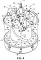
- the agitator air motor 64 is used to turn an agitator 66 ( Figs. 4 , 5 and 9 for example) to assist in fluidizing the powder coating material.
- the agitator air motor 64 operates from pressurized air provided by air tubing 68.
- a switch function 70 such as for example a limit switch, may be used to interrupt pressurized air supplied from a source (such as shop air for example) via an air hose 72 to an air inlet fitting 74, should an operator or other personnel move, loosen, separate or otherwise remove the cover 26. This will prevent the agitator motor 64 from operating if the cover 26 has been separated from the hopper body 12.
- a grounding strap 76 may be used in a conventional manner to electrically ground the hopper 10.
- Figs. 2A, 2B and 3 illustrate the hopper body 12 and the fluidizing subassembly 22 in simpler views.
- the hopper body 12 may be provided with handles 78 (only one is viewable in these figures) to ease transporting and positioning the hopper 10.
- the level sensor arrangement 54 provides a sensing port 80 to the hopper 10 interior.
- the fluidizing drum 20 may include a housing 82 that supports a fluidizing plate 84.
- a suitable gasket or seal 86 may be used to provide a fluid tight seal between the fluidizing bed 20 and the lower end of the hopper body 12.
- the fluidizing plate 84 may comprise any porous material that allows air flow there through to fluidize the powder coating material added into the hopper 10 above the plate 84.
- a suitable material for the fluidizing plate 84 is polyethylene, as is well known.
- the housing 82 includes a fluidizing air fitting 88 that is connectable to a fluidizing air hose 90 ( Fig. 1 ). Fluidizing air enters the drum 20 through the fitting 88 and into the housing 82 so that pressurized fluidizing air evenly flows up through the fluidizing plate 84.
- a post or standoff 92 may be used to support the fluidizing plate 84 against sagging or falling through the gasket 86 due to weight of powder on top of the plate 84.
- the hopper 10 further includes a baffle 100.
- the baffle 100 in this example comprises an open ended right cylinder baffle body 102 that may be supported within the hopper body 12 such as by studs 105 ( Fig. 7 ) that are attached to the underside of the cover 26.
- the baffle body 102 has an outside diameter D1 that is less than the inside diameter D2 of the hopper body 12. With D1 ⁇ D2, and with the baffle body 102 preferably generally centered within the hopper body 12, an annular region 104 for adding powder coating material is provided between the baffle 100 and the hopper body 12.
- the annular region 104 is used for adding or supplying powder coating material to the hopper 10 so that the baffle 100 defines an interior quiet zone or low turbulence zone 106 (see Figs. 5 and 7 ) within the volume of the cylindrical baffle body 102 that is generally isolated from the turbulence and higher flow of the added powder coating material.
- the suction tubes 46 for the feed pumps 34 extend down into this quiet low turbulence zone 106 (in other words, the suction tubes 46 extend down within the baffle 100, see Fig. 7 ) so that a uniformly distributed and low turbulence supply of fluidized powder is sucked up by the feed pumps 34 to the application devices.
- the hopper 10 has a central longitudinal axis X, which, for example, the agitator 66 extends along down into the hopper 10.
- the studs 105 provide an axial offset Y ( Fig. 7 ) between the upper end 102a of the baffle body 102 and the lower surface 107 of the cover 26.
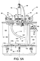
- This axial offset Y provides an upper gap 108 ( Fig. 5A ) to allow pressure equalization within the hopper 10.
- This upper gap 108 may be on the order, for example, of about 20,32 mm (.8 inches)for a hopper 10 of inside diameter of about 16 inches, but these numbers are only exemplary and may be changed as needed for a particular application.
- the axial length of the baffle body 102 is also selected so as to allow for a lower gap 110 between a lower end 102b thereof and the fluidizing plate 84.
- This lower gap 110 allows powder coating material to flow into the interior region or low turbulence zone 106 of the baffle 100, and accommodates agitator arms 112 that are part of the agitator 66.
- the agitator arms 112 in this example may extend out from the main agitator shaft 114 like spokes on a wheel, so as to help fluidize and uniformly distribute powder coating material as the agitator 66 rotates.
- the agitator arms 112 preferably although not necessarily extend radially beyond the outer perimeter of the baffle 100 so as to stir the fluidized powder over most or all of the surface of the fluidizing plate 84 including within the low turbulence zone 106 and the annular zone 104.
- the agitator arms 112 may be disposed fairly near the surface of the fluidizing plate 84 and extend through the lower gap 110.
- the suction tubes 46 preferably although not necessarily extend axially down to near but above the lower end 102b of the baffle body 102, so as not to be exposed to the more turbulent flow that is present in the annular region 104 (as shown in phantom in Fig. 5A ).
- Inlet tubes 116 may be used to add powder coating material into the annular region 104.
- two inlet tubes 116 are provided.
- Each inlet tube 116 has a first end 118 that extends up into its associated powder inlet connection 58, and a second end 120 that is positioned within the annular region 104.
- the second ends 120 thus present outlet openings 122 through which powder coating material is supplied to the hopper 10 within the annular region 104.
- These openings 122 preferably although not necessarily are positioned axially above the lower end 102b of the baffle body 102 so as to reduce turbulence in the quiet zone 104.
- outlet openings 122 are preferably although not necessarily diametrically opposite each other, and if more than two inlet tubes are used, preferably evenly distributed about the circumference of the annular region. In some designs, however, a single inlet tube may be used. Using more than one inlet tube 116 allows for less delivery air volume to reduce over pressure, and also allows for a lower inlet air and powder velocity.
- the inlet tubing 116 may have a gentle radius curvature to it so as to reduce impact fusion of powder coating material against the internal surface of the tubes.
- the tubes 116 are disposed so that powder coating material exiting through the outlet openings 122 has a downward directional component, while at the same time entering the annular region 104 generally tangentially so that added powder coating material flows in a downward helical direction represented by the arrow Z ( Fig. 4 ) toward the lower gap 110.
- these flow orientations are optional, they tend to provide more uniform powder distribution and also assist the powder particles to decelerate as they move towards the fluidizing plate 84 and the lower gap 110.
- the inlet tubes 116 each introduce powder coating material into the annular region 104 preferably in the same direction of rotation Z.
- the agitator 66 is rotated in this same direction Z.
- the direction Z may be clockwise or counterclockwise as needed.
- fluidizing air flow may be about (3-5,097 - 6,79 cubic meter/hour 4 cubic feet per minute (cfm) 8,5 - 10,2 m 3 /h, while the bulk air flow for adding powder coating material into the annular region 104 may be about 5-6 cfm.
- the agitator may rotate at any suitable speed, and we have found 1,5 - 1,66 Hz (90-1,00 rpm) works well.
- the venting pumps 28 may be operated so as to reduce pressure within the hopper 10 that may otherwise build up due to the fluidizing air from the fluidizing plate 84.
- the venting pumps 28 will typically need to vent even more air because of the increase in air flow into the hopper 10 from the bulk supply pumps 62.
- each venting pump 28 has a suction inlet that is in fluid communication with a port 124 that is open to the hopper interior volume so as to suck air from the upper region of the hopper 10 as needed to maintain preferably though not necessarily a slightly negative pressure within the hopper 10.
- an overall powder coating material application system 200 may include the bulk supply 60, one or more material application devices 202, a supply hopper such as, for example the exemplary hopper 10 described herein, and a control circuit or system 204.
- the material application device 202 may be any suitable spray gun for example as are well known in the art. Another suitable application device is described herein below.
- the control circuit or system 204 may be realized using hardware and software as needed, and control systems for powder coating material application systems are well known in the art.
- control systems typically include one or more functions such as, for example, an air control function 206 for supplying the atomizing air 208 and flow air 210 to the feed pumps 34; a bulk feed control function 212 for operating the bulk feed pump 62 at the appropriate times, particularly when powder coating material is demanded to the hopper 10.
- the control system 204 typically will also include an electrical power and gun control functions 214. All of these system control functions are well known in the art.
- control circuit 204 may include with the bulk feed control input signal 216 from the level sensor 54. This signal may be used to indicate a demand for powder into the hopper 10.
- the feed control 212 activates via control line 213 the bulk supply pump 62 which may use transport air to move powder from the bulk supply 60 into the hopper 10 via the inlet tubes 116.
- the feed control 212 (or another control circuit or function as needed) may also be used to control operation of the venting pumps 28. As noted above, for Venturi-type venting pumps, the air flow or suction pulled by the venting pumps 28 may be controlled by the flow air to the pump inlets 30.
- the feed control 212 may use a venting pump control signal 218 to operate a control valve 220.
- the control valve 220 may be used to deliver two different pressures or air flow rates 222 to the venting pump inlets 30.
- the venting pumps 28 may be operated at a lower or idle suction rate, for example, about 5,097 - 6,79 m 3 /h (3-4 cfm). This lower suction is used to remove fluidizing air so as to maintain a negative pressure within the hopper 10.
- This lower suction is used to remove fluidizing air so as to maintain a negative pressure within the hopper 10.
- powder is added, however, in addition to the fluidizing air there is transport air added with the powder feed from the feed pumps 62.
- the feed control 212 may be used to switch the control valve 220 so as to increase the flow air 222 to the venting pump inlets 30 to increase the suction, for example, to about 11,89 - 13,59 m 3 /h (7-8 cfm).
- the amount of venting suction for any given system will depend in part on the fluidizing air flow rate and the flow rate of air for transporting powder from the pumps 62 to the hopper 10.
- the increased flow air to the venting pumps 28 increases the suction of the venting pumps 28 to pull more air from the hopper 10 as powder is being added.
- the venting pumps 28 may be returned to the idle suction rate.
- the amount of increased venting suction needed when powder is added to the hopper 10, as well as the idle suction needed when powder is not being added, will be a function of many factors including but not limited to the amount of fluidizing air, size of the hopper, properties of the powder material such as density and particle size, amount of transport air, feed rates into the hopper and so on. Accordingly, for each set-up, the required idle suction and increased suction may be determined empirically and pre-set into the venting control system 204 as part of the set-up procedures.
- pressure sensors that monitor internal pressure in the hopper 10, such as near the cover 26, for example, may be used to provide a closed loop pressure feedback control in order to maintain the desired internal hopper pressure when powder is being added and when powder is not being added.
- the pressure sensor feedback signals may be used to control either fluidizing air flow, the venting pump 28 suction, or both.
- pressure data could be viewed and manual adjustments made to control the fluidization air flow, the venting pump suction, or both.
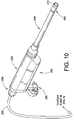
- the spray gun 250 may correspond to the coating material applicator 202 of Fig. 5 herein.
- the spray gun 250 may include a main gun housing 252 having a powder inlet end 254 that receives a powder feed hose 256.
- the feed hose 256 is connected at its opposite end to the outlet of a feed pump, for example a feed pump 34 in Fig. 1 .
- the feed hose 256 may correspond, for example, to the feed hose 42 of the Fig. 5 embodiment herein.
- the gun housing 252 is adapted for connection with a lance assembly 258.
- a nut 253 may be used to secure the lance assembly 258 to the main housing 252.
- the spray gun 250 is well suited for spraying the interior of long tubular containers, although it may be used with other containers as needed.
- the lance 258 includes a nozzle 260 at the distal end of the lance.
- the spray gun illustrated in Fig. 10 is a bar mount style gun and includes a bar mount assembly 262 to attach the spray gun 250 to a bar associated with a support structure for the gun (not shown), as is well known in the art.
- the spray gun may alternatively be a tube mount style gun in which the main gun housing 252 may be supported by a tubular member associated with a support structure of the spray gun. Manual spray guns may also be used.
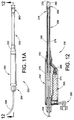
- the main housing 252 encloses an internal high voltage multiplier assembly 264.
- the multiplier assembly 264 includes an output 266 that is electrically connected by a resistor/conductor assembly 268 to an electrode assembly 270 ( Fig. 15 ).
- the multiplier 264 produces a high voltage output that is applied to a charging electrode tip 272 (also shown in Fig. 5 ) to electrostatically charge powder coating particles that exit through the nozzle 260.
- the feed hose 256 extends into the main housing and fits over a barbed end 274 of a powder tube 276 that may be provided as part of the lance assembly 258.
- a powder tube 276 that may be provided as part of the lance assembly 258.
- the powder tube 276 inside diameter is about the same as the inside diameter of the feed hose 256 that extends back to the feed pump outlet.
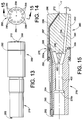
- the powder tube 276 extends through the lance assembly 258 up to an electrode assembly holder 278 ( Fig. 15 ).
- the electrode assembly 270 may include a first electrode wire 280 having a first contact spring 282, wherein the first electrode wire passes through a bore 284 in the electrode holder 278 and has a distal end 280a that makes electrical contact with a conductive seal member 295.
- the seal member 295 is axially compressed between the first electrode wire 280 and a second electrode contact spring 286 that is in electrical contact with a second electrode wire 287 that terminates at the electrode tip 272.
- the electrode 272 passes through a bore 288 in the nozzle 260 so that the electrode tip may be preferably positioned in the middle of the nozzle just forward of the nozzle face 290.
- the electrode holder 278 may include a bore 278a that receives the forward end of the powder tube 276 ( Fig. 15 ).
- the nozzle 260 may include nozzle information-related coding or indicia, for example, one or more optional grooves 292.
- These grooves 292 may indicate the type of nozzle, such as the number of powder flow passage, angles of the passages, diameters and other information of interest.
- the grooves may be colored to provide additional information. Many different shapes other than grooves, as well as combinations of shapes, size and color, including raised rings for example, may alternatively be used.
- the charging electrode first contact spring 282 has a contact end that makes electrical contact with the resistor/conductor assembly 268 ( Fig. 12 ).
- the applicator 250 may, alternatively, be configured as a non-electrostatic device as well.
- the electrode tip 272 exits the nozzle 260 so as to be about in the center of the powder coating material spray pattern.
- the charging electrode 287 may pass through an outer portion of the nozzle 260 before terminating in the central region of the powder flow passages (296), or alternatively may extend straight through the center of the nozzle, for example. Still further the charging electrode may extend through a rib (not shown) along an outer periphery of the nozzle 260.
- the nozzle 260 may include a main nozzle body 294 with a plurality of powder coating material flow passages 296 formed therein.
- the nozzle body 294 may be attached to the electrode holder 278 by any suitable arrangement, such as a press fit as illustrated in Fig. 15 .
- Suitable seals such as the o-rings 295 may be used to contain powder coating material from escaping to the atmosphere, as well as from flowing down the electrode bore 288.
- the flow passages 296 are preferably although not necessarily discrete from each other. Because of the cross-section orientation of Fig. 15 , only one flow passage 296 is shown, and in some applications as few as two flow passages 296 might be used.
- any plurality number of flow passages 296 may be used, and we have found that three up to twelve such passages work well, particularly for interior coating of long narrow containers, to name one example.
- the embodiment of Figs. 13-15 illustrate the use of twelve flow passages 296.
- the flow passages 296 diverge at an angle ⁇ , which is the half angle referenced to the central longitudinal axis Y of the nozzle 260; however, as will be further explained herein, the flow passages 296 may take on more complex arrangements such as illustrated in Figs. 16A-16U .
- the angle ⁇ may be zero degrees meaning that the flow passages 296 extend parallel to the axis Y.
- the flow passages 296 extend from an interior surface 298, about the base of a conical tip 400.
- the conical tip 400 extends axially rearward to assist uniform distribution of powder coating material that flows into the nozzle 260 to pass through the plurality of flow passages 296.
- the cone angle ⁇ which is the half angle referenced to the axis Y, may be the same or different from the angle ⁇ . Suitable but not required ranges for the angle ⁇ is about 0° to about 20° and will be determined in part by the internal diameter of the container being coated, as well as whether more than one nozzle is being used for a coating operation. Suitable but not required ranges for the angle ⁇ is about 10° to about 15°, with 15° being illustrated in the drawings.
- the nozzle 260 and the flow passages 296 provide a more uniformly dispersed powder spray pattern than is achieved in prior nozzle designs. Accordingly, the nozzle 260 with a plurality of discrete powder flow passages 296 facilitate use of the applicator 250 to coat open or closed end containers while the container may be rotationally stationary during a coating operation.
- rotationally stationary is meant that there is no relative rotation between the powder coating material applicator 250, such as the nozzle 296, for example, and the container being coated during a coating operation. In a more specific example, the container may be coated without having to rotate the container itself.
- the use of discrete multiple flow passages also produces a more uniform film thickness. Can or nozzle rotation may be alternatively used as needed.
- placing the charging electrode tip 272 in about the center of the spray pattern improves the charging of the powder particles, particularly with the more uniform distribution of powder in the spray pattern due to the use of the nozzle 260 with a plurality of discrete flow passages 296.
- Each flow passage 296 in the exemplary embodiment has a circular cross-section and a diameter that is constant along the entire length of each flow passage.
- such geometry is not required, and may be changed as needed to achieve particular spray patterns, flow velocities and so on.
- the flow passages might alternatively have a varying diameter, or may have a cross-sectional shape other than circular.
- the discrete flow passages 296 open at an end face of the nozzle 260 (see the examples below), with the openings preferably being evenly spaced about the longitudinal axis of the nozzle.
- the total cross-sectional area of the flow passages be at least equal to or greater than the cross-sectional area of the nozzle inlet flow passage 402 that is just upstream from the nozzle 260.
- the cross-sectional area of the nozzle inlet flow passage 402 is preferably but need not be about the same as the cross-sectional area of the inside diameter of the powder tube 276, such that there is a generally constant cross-sectional area for the powder flow path that extends from the outlet of the feed pump 34 all the way through the nozzle 260.
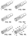
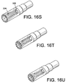
- Figs. 16A-16U illustrate a wide variety of different nozzle 300 designs, in particular for the configuration of a plurality of discrete powder flow passages 302.
- the variations involve various angles and directions of powder flow, along with different end pattern configurations where the flow passages open at the end face 304 of the nozzle.
- Figs. 16A-16J illustrate diverging angles wherein various ones of the discrete passages may have the same angle or different angles relative to a central longitudinal axis Y of the nozzle. Exemplary angles may be in the range of about three to about eighteen degrees relative to the Y axis for the primary powder passages.
- the passages may have a uniform diameter, for example about 2 millimeters.
- the charging electrode 306 extends from a radially outer portion of the nozzle body 308, but that the charging electrode tip 310 preferably although not necessarily is disposed in about the central region of the spray pattern.
- Figs. 16K-16O , 16T and 16U illustrate examples of compound flow passages in which the flow passages may include a straight portion 312--meaning that the flow passage is generally parallel the central axis Y or at zero degrees-- before diverging as along 314 (see for example Fig. 16L , for simplicity we only label Fig. 16L ).
- different divergence angles may be used for various of the discrete flow passages within a nozzle so as to select a particular end face pattern.
- some of these exemplary designs include a central cone or other raised portion 316 in the nozzle end face.
- the end face 318 may be raised, dome shaped or have other profiles as needed.
- the end face 304 is flat. In all the embodiments, such features including the end face geometry and the end face pattern of the flow passages 302, may be used to effect a particular spray pattern effect from the nozzle 300.
- Figs. 16P-16R illustrate embodiments wherein the flow passages 320 diverge not only axially but also radially, having the appearance of crossing over each other or a twist arrangement (see for example, Fig. 16Q ). Such an arrangement may be used, for example, to impart a swirl effect to the spray pattern.
- a flow passage may include a first portion 322 that diverges away from the central axis Y and a second portion 324 that converges back towards the axis Y.
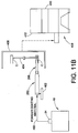
- a typical tube shaped container C that may be coated with the apparatus disclosed herein is illustrated in phantom in Fig. 11A , and a system for coating the container is illustrated in Fig. 11B .
- a typical tube shaped container C may be, for example, an aerosol can for hairspray, or a metal water bottle.
- Suitable containers may have an axial length that is about three times the container diameter, and a typical diameter range of about a 12,7 mm (half-inch) or greater, with lengths about 25,4 mm (one) and 12,7 mm (one-half inch) or greater; with a typical range being about 25,4 mm (one inch) in diameter and a length of about 76,2 mm (three inches) to about 152,4 mm (six inches) or more in length for an aerosol can, and about 50,8 mm (two inch) diameter and a length of about 152,4 - 304,8 mm (six to twelve inches) for a metal water bottle, to name two examples; however, these dimensions are intended to be only exemplary numbers and not limiting.
- the lance 258 may be sufficiently elongated so as to allow the nozzle 260 to be positioned well inside the container.
- the length of the lance 258 may be changed as needed to accommodate different length and internal diameter containers.
- such an apparatus may be used to carry out another method of this disclosure, in which fluidized powder coating material is drawn from a quiet zone of a powder coating material hopper, conveyed to a spray gun and out a nozzle having a plurality of flow passages, to coat an interior surface of an elongated tubular container.
- the coating operation may be performed with relative rotation between the nozzle of the spray gun and the container surface.
- the hopper 10 of this embodiment supplies powder through a pump 34 via a hose 400 to spray gun 252.
- the spray gun 252 may be mounted on a reciprocator 402 to reciprocate the lance 258 of the gun 252 into and out of the container C.
- the container C is mounted to a star wheel 404 which indexes the container into position in front of the spray gun 252.
- the containers C are held onto the star wheel 404 by vacuum chucks and conventional equipment is used to load containers C onto the star wheel prior to coating and unload them from the star wheel after they have been coated.
- An overspray collection hood 406 is connected to a powder overspray collection system 408 that recovers any powder coating material which does not adhere to the container C.
- the overspray collection system 408 may be of a convention type and will include, for example, a vacuum source 410, such as a fan, to drawn transport air-entrained powder from the hood 406 and convey the air-entrained powder onto the exterior of filter cartridges (not shown) where the powder is separated from the transport air and typically periodically reverse air pulsed off the cartridges and collected in a hopper (not shown) in the bottom of the collection system 408.
- a final filter, or after-filter, 412 traps any residual powder that passes through the filter cartridges before the transport air is discharged from the overspray collection system 408.
Landscapes
- Engineering & Computer Science (AREA)
- Mechanical Engineering (AREA)
- Electrostatic Spraying Apparatus (AREA)
- Air Transport Of Granular Materials (AREA)
- Coating Apparatus (AREA)
- Application Of Or Painting With Fluid Materials (AREA)
- Nozzles (AREA)
Claims (14)
- Zuführbehälter für Pulverbeschichtungsmaterial mit einem Zuführbehälterkörper (12) mit einem Zylinder, einem Deckel (26) an einem oberen Ende des Zuführbehälterkörpers (12), einem Wirbelbett an einem unteren Ende des Zuführbehälterkörpers (12), einer sich im Inneren des Zuführbehälterkörpers (12) befindenden und in Richtung des Wirbelbettes erstreckenden Trennwand (100), mindestens einem Pulvereinlass, der dazu angeordnet ist, Pulver in den Zuführbehälterkörper (12) zuzuführen, und einem Pulverauslass, dadurch gekennzeichnet, dass die Trennwand (100) einen Zylinder mit einem kleineren Durchmesser als der Durchmesser des Zuführbehälterkörpers (12) umfasst, um einen ringförmigen Bereich (104) zwischen dem Zuführbehälterkörper (12) und der Trennwand (100) auszubilden, wobei der Pulvereinlass in dem ringförmigen Bereich (104) angeordnet ist, sodass die Trennwand (100) eine Zone (106) niedriger Turbulenz für ein verflüssigtes Pulver bereitstellt, wenn Pulver dem Zuführbehälter hinzu geführt wird, wobei der Pulverauslass zum Entnehmen von Pulver aus der Zone (106) niedriger Turbulenz angeordnet ist.
- Zuführbehälter nach Anspruch 1, bei dem ein unterer Abstand (110) zwischen dem Boden der Trennwand (100) und dem Wirbelbett bereitgestellt ist und ein oberer Abstand (108) zwischen der Trennwand (100) und dem Deckel (26) bereitgestellt ist.
- Zuführbehälter nach Anspruch 2, mit einem in dem Zuführbehälter angeordneten Rührer (66), wobei der Rührer (66) dazu betreibbar ist, verflüssigtes Pulver in der Zone (106) niedriger Turbulenz und dem ringförmigen Bereich (104) umzurühren.
- Pulverbeschichtungssystem mit dem Zuführbehälter nach einem der voranstehenden Ansprüche, einer Pulversprühpistole (250, 252) und einer Pumpe (34), die Pulver aus der Zone (106) niedriger Turbulenz zieht und das Pulver in die Sprühpistole (250, 252) pumpt.
- System nach Anspruch 4, wobei die Sprühpistole (250) eine Düse (260) umfasst, wobei die Düse eine Mehrzahl einzelner um eine Längsachse der Düse angeordnete Strömungskanäle (296, 302) umfasst.
- Kombination nach Anspruch 5, wobei die Sprühpistole (250, 252) eine Elektrode (272) umfasst, wobei die Elektrode (272) sich durch die Düse (260) entlang einer Längsachse der Düse erstreckt.
- Kombination nach Anspruch 6, wobei die einzelnen Strömungskanäle (296, 302) gleichmäßig um eine Spitze der sich von einem Auslassen der Düse (260) erstreckenden Elektrode (272) angeordnet sind.
- Kombination nach Anspruch 7, wobei die einzelnen Strömungskanäle (296, 302) einen kreisförmigen Querschnitt umfassen.
- System nach einem der Ansprüche 4 bis 8, wobei die Sprühpistole (252) an einer Bewegungseinrichtung (402) angebracht ist.
- Verfahren zum Auftragen von Pulverbeschichtungsmaterial auf eine Innenfläche eines Behälters, umfassend die Schritte Verflüssigen von Pulverbeschichtungsmaterial in einem Pulverbeschichtungsmaterialzuführbehälter, Saugen von verflüssigtem Pulverbeschichtungsmaterial aus dem Pulverbeschichtungsmaterial- Zuführbehälter und Befördern des verflüssigten Pulvers aus dem Zuführbehälter zu einer Sprühpistole (250, 252) und aus einer Düse (260) der Sprühpistole heraus, um eine Innenfläche des Behälters zu beschichten, wobei der Zuführbehälter einen Zuführbehälterkörper (12) mit einem Zylinder, einen Deckel (26) an einem oberen Ende des Zuführbehälterkörpers (12), ein Wirbelbett an einem unteren Ende des Zuführbehälterkörpers (12), eine sich im Inneren des Zuführbehälterkörpers (12) befindende und in Richtung des Wirbelbettes erstreckende Trennwand (100), mindestens einen Pulvereinlass, der dazu angeordnet ist, Pulver in den Zuführbehälterkörper (12) zuzuführen, umfasst, dadurch gekennzeichnet, dass die Trennwand (100) einen Zylinder mit einem kleineren Durchmesser als der Durchmesser des Zuführbehälterkörpers (12) umfasst, um einen ringförmigen Bereich (104) zwischen dem Zuführbehälterkörper (12) und der Trennwand (100) auszubilden, wobei der Pulvereinlass in dem ringförmigen Bereich (104) angeordnet ist, sodass die Trennwand eine Zone (106) niedriger Turbulenz für verflüssigtes Pulver bereitstellt, wenn Pulver in den Zuführbehälter hinzu geführt wird, wobei das Verfahren das Hinzufügen neuen Pulvers in den Zuführbehälter durch den Einlass in den ringförmigen Bereich (104) und das Befördern von verflüssigtem Pulver in die Sprühpistole (250, 252) aus der Zone (106) niedriger Turbulenz einschließt.
- Verfahren nach Anspruch 10, wobei ein Beschichtungsvorgang elektrostatisch ausgeführt wird.
- Verfahren nach Anspruch 10, wobei ein Beschichtungsvorgang unter Verwendung einer Düse (260) ausgeführt wird, die dazu angepasst ist, teilweise in einen offenen oder geschlossenen Endbehälter eingeführt zu werden, wobei die Düse eine Mehrzahl einzelner um eine Längsachse der Düse angeordneter Strömungskanäle (296, 302) aufweist, wobei Pulver durch die Strömungskanäle (296, 302) strömt, um das Behälterinnere während eines Beschichtungsvorgangs zu beschichten.
- Verfahren nach Anspruch 10, wobei die Trennwand (100) eine Unterkante aufweist, die über dem Wirbelbett angeordnet ist.
- Verfahren nach einem der Ansprüche 10 bis 13, das ein Hin- und Herbewegen der Sprühpistole (250, 252) in und aus dem Behälter umfasst.
Applications Claiming Priority (2)
| Application Number | Priority Date | Filing Date | Title |
|---|---|---|---|
| US13824608P | 2008-12-17 | 2008-12-17 | |
| PCT/US2009/068238 WO2010077936A1 (en) | 2008-12-17 | 2009-12-16 | Powder hopper with quiet zone, a combination of a powder hopper and a powder spray gun and a method of operating a powder hopper |
Publications (2)
| Publication Number | Publication Date |
|---|---|
| EP2376236A1 EP2376236A1 (de) | 2011-10-19 |
| EP2376236B1 true EP2376236B1 (de) | 2016-04-13 |
Family
ID=41818749
Family Applications (1)
| Application Number | Title | Priority Date | Filing Date |
|---|---|---|---|
| EP09795861.5A Revoked EP2376236B1 (de) | 2008-12-17 | 2009-12-16 | Pulverzuführbehälter mit einer beruhigten zone, ein pulverzuführbehälter in kombination mit einer sprühpistole und eine methode um einen pulverzuführbehälter zu betreiben |
Country Status (4)
| Country | Link |
|---|---|
| US (2) | US8783208B2 (de) |
| EP (1) | EP2376236B1 (de) |
| JP (1) | JP5575148B2 (de) |
| WO (1) | WO2010077936A1 (de) |
Families Citing this family (12)
| Publication number | Priority date | Publication date | Assignee | Title |
|---|---|---|---|---|
| US9027506B2 (en) | 2011-05-02 | 2015-05-12 | Nordson Corporation | Dense phase powder coating system for containers |
| US9867931B2 (en) | 2013-10-02 | 2018-01-16 | Cook Medical Technologies Llc | Therapeutic agents for delivery using a catheter and pressure source |
| JP2014188394A (ja) * | 2013-03-26 | 2014-10-06 | Ngk Insulators Ltd | ノズル、及び、そのノズルを用いたハニカムフィルタ製造装置 |
| US11007717B2 (en) | 2016-05-12 | 2021-05-18 | Hewlett-Packard Development Company, L.P. | Outlet structure |
| IT201600097204A1 (it) * | 2016-09-28 | 2018-03-28 | Cristanini Spa | Apparato per lo spruzzaggio di una miscela abrasiva verso una superficie delicata per la rimozione di scritte, disegni o graffiti dalla stessa |
| CN112055650A (zh) * | 2018-09-28 | 2020-12-08 | 惠普发展公司,有限责任合伙企业 | 3d打印系统 |
| CN115697176A (zh) | 2020-06-05 | 2023-02-03 | 库克医学技术有限责任公司 | 用于递送治疗剂的医疗窥镜 |
| WO2023287654A1 (en) | 2021-07-14 | 2023-01-19 | Cook Medical Technologies, LLC | Systems and methods for preventing clogging of a delivery system |
| CN115055297B (zh) * | 2022-04-20 | 2025-02-25 | 宁波立成涂装技术有限公司 | 一种应用于静电喷枪的粉末存储杯 |
| US12496429B2 (en) | 2022-10-18 | 2025-12-16 | Cook Medical Technologies Llc | Systems and methods for delivering pressurized fluid to a target site alone or in conjunction with therapeutic agents |
| CN116510993B (zh) * | 2023-04-11 | 2026-02-27 | 巨力自动化设备(浙江)股份有限公司 | 一种涂覆工艺 |
| CN118571641B (zh) * | 2024-08-01 | 2024-10-29 | 湖南铭叶磁材科技有限公司 | 一种用于磁粉包覆的喷淋式辅料添加装置 |
Citations (16)
| Publication number | Priority date | Publication date | Assignee | Title |
|---|---|---|---|---|
| US2123537A (en) | 1935-06-18 | 1938-07-12 | Marr Philip George | Method and apparatus for spraying powder or the like |
| US2600528A (en) | 1950-09-22 | 1952-06-17 | Sun Oil Co | Apparatus for elevating contact material |
| US2758884A (en) | 1950-06-28 | 1956-08-14 | Houdry Process Corp | Transfer and circulation of solid granular material |
| US3412898A (en) | 1966-02-07 | 1968-11-26 | British Titan Products | Powder feeder |
| US3791341A (en) | 1970-05-28 | 1974-02-12 | Allis Chalmers Mfg Co | Electrostatic resin powder spray system |
| JPS5883756U (ja) | 1981-12-02 | 1983-06-07 | 株式会社日立製作所 | A形電球用静電塗装ノズル |
| US4730647A (en) | 1986-12-08 | 1988-03-15 | Nordson Corporation | Powder feeder apparatus |
| EP0452152A2 (de) | 1990-04-13 | 1991-10-16 | Nordson Corporation | Zuführbunker für Pulver |
| WO1992002349A2 (en) | 1990-08-04 | 1992-02-20 | The removal of material from surfaces | |
| EP0516462A1 (de) | 1991-05-29 | 1992-12-02 | Nordson Corporation | Elektrostatische Pulverbeschichtung |
| US5603566A (en) | 1995-11-21 | 1997-02-18 | Abb Flexible Automation Inc. | Powder hopper with internal air assist |
| GB2310816A (en) | 1996-03-05 | 1997-09-10 | Ceradent Ltd | A feed mechanism for use in powder spraying utilising a porous member |
| EP0974400A2 (de) | 1993-05-25 | 2000-01-26 | Nordson Corporation | Pulverbeschichtungssystem |
| JP3565917B2 (ja) | 1994-10-21 | 2004-09-15 | 旭サナック株式会社 | 粉体の定量供給装置 |
| DE102005013703A1 (de) | 2005-03-24 | 2006-10-05 | Fraunhofer-Gesellschaft zur Förderung der angewandten Forschung e.V. | Verfahren und Vorrichtung zum Erzeugen eines Aerosols |
| US20070235558A1 (en) | 2004-10-08 | 2007-10-11 | Sames Technolgoies | System for continuously metering and transporting a powder, the use of the system, and a coating powder sprayer installation including the system |
Family Cites Families (7)
| Publication number | Priority date | Publication date | Assignee | Title |
|---|---|---|---|---|
| US3826540A (en) * | 1973-03-21 | 1974-07-30 | Elektro Ion | Powder hopper for electrostatic powder spraying apparatus |
| JPS5546301Y2 (de) * | 1975-05-30 | 1980-10-30 | ||
| JP3732526B2 (ja) * | 1991-05-29 | 2006-01-05 | ノードソン株式会社 | 静電粉末コーティング装置 |
| US5654042A (en) * | 1992-12-17 | 1997-08-05 | Nordson Corporation | Powder coating system for difficult to handle powders |
| US5743958A (en) * | 1993-05-25 | 1998-04-28 | Nordson Corporation | Vehicle powder coating system |
| US5725670A (en) * | 1994-02-18 | 1998-03-10 | Nordson Corporation | Apparatus for powder coating welded cans |
| JP3429316B2 (ja) * | 1994-10-11 | 2003-07-22 | ノードソン コーポレーション | 車両粉体塗装システム |
-
2009
- 2009-12-16 WO PCT/US2009/068238 patent/WO2010077936A1/en not_active Ceased
- 2009-12-16 JP JP2011542375A patent/JP5575148B2/ja not_active Expired - Fee Related
- 2009-12-16 EP EP09795861.5A patent/EP2376236B1/de not_active Revoked
- 2009-12-16 US US13/140,066 patent/US8783208B2/en not_active Expired - Fee Related
-
2014
- 2014-05-13 US US14/275,953 patent/US20140248437A1/en not_active Abandoned
Patent Citations (16)
| Publication number | Priority date | Publication date | Assignee | Title |
|---|---|---|---|---|
| US2123537A (en) | 1935-06-18 | 1938-07-12 | Marr Philip George | Method and apparatus for spraying powder or the like |
| US2758884A (en) | 1950-06-28 | 1956-08-14 | Houdry Process Corp | Transfer and circulation of solid granular material |
| US2600528A (en) | 1950-09-22 | 1952-06-17 | Sun Oil Co | Apparatus for elevating contact material |
| US3412898A (en) | 1966-02-07 | 1968-11-26 | British Titan Products | Powder feeder |
| US3791341A (en) | 1970-05-28 | 1974-02-12 | Allis Chalmers Mfg Co | Electrostatic resin powder spray system |
| JPS5883756U (ja) | 1981-12-02 | 1983-06-07 | 株式会社日立製作所 | A形電球用静電塗装ノズル |
| US4730647A (en) | 1986-12-08 | 1988-03-15 | Nordson Corporation | Powder feeder apparatus |
| EP0452152A2 (de) | 1990-04-13 | 1991-10-16 | Nordson Corporation | Zuführbunker für Pulver |
| WO1992002349A2 (en) | 1990-08-04 | 1992-02-20 | The removal of material from surfaces | |
| EP0516462A1 (de) | 1991-05-29 | 1992-12-02 | Nordson Corporation | Elektrostatische Pulverbeschichtung |
| EP0974400A2 (de) | 1993-05-25 | 2000-01-26 | Nordson Corporation | Pulverbeschichtungssystem |
| JP3565917B2 (ja) | 1994-10-21 | 2004-09-15 | 旭サナック株式会社 | 粉体の定量供給装置 |
| US5603566A (en) | 1995-11-21 | 1997-02-18 | Abb Flexible Automation Inc. | Powder hopper with internal air assist |
| GB2310816A (en) | 1996-03-05 | 1997-09-10 | Ceradent Ltd | A feed mechanism for use in powder spraying utilising a porous member |
| US20070235558A1 (en) | 2004-10-08 | 2007-10-11 | Sames Technolgoies | System for continuously metering and transporting a powder, the use of the system, and a coating powder sprayer installation including the system |
| DE102005013703A1 (de) | 2005-03-24 | 2006-10-05 | Fraunhofer-Gesellschaft zur Förderung der angewandten Forschung e.V. | Verfahren und Vorrichtung zum Erzeugen eines Aerosols |
Also Published As
| Publication number | Publication date |
|---|---|
| JP2012512026A (ja) | 2012-05-31 |
| WO2010077936A1 (en) | 2010-07-08 |
| EP2376236A1 (de) | 2011-10-19 |
| JP5575148B2 (ja) | 2014-08-20 |
| US20140248437A1 (en) | 2014-09-04 |
| US8783208B2 (en) | 2014-07-22 |
| US20120021133A1 (en) | 2012-01-26 |
Similar Documents
| Publication | Publication Date | Title |
|---|---|---|
| EP2376236B1 (de) | Pulverzuführbehälter mit einer beruhigten zone, ein pulverzuführbehälter in kombination mit einer sprühpistole und eine methode um einen pulverzuführbehälter zu betreiben | |
| JP3489688B2 (ja) | 粉体を加工物に塗布する方法及び装置 | |
| CN103619486B (zh) | 用于容器的密相粉末涂覆系统 | |
| US3873024A (en) | Apparatus for spraying a plurality of different powders | |
| EP0962258B1 (de) | Pulverförderungsvorrichtung mit einem Fluidiesierungsrohr | |
| JPH11244738A (ja) | 基板上にコ―ティングをスプレイするための収束スプレイノズル及び方法 | |
| US9657740B2 (en) | Powder supplying device for a powder coating installation | |
| US8123147B2 (en) | Powder coating system and components | |
| US9415409B2 (en) | Device for conveying coating powder from a powder container | |
| US6620243B1 (en) | Fluidized bed powder handling and coating apparatus and methods | |
| CN109070112A (zh) | 用于将涂料粉末输送至粉末涂布器的粉末输送器、粉末涂布系统和用于操作粉末输送器的方法 | |
| JPS62699A (ja) | 回転拡散器を具備するベンチユリ粉体ポンプ | |
| GB2325870A (en) | Electrostatic spray gun for powder coating | |
| CN113226564B (zh) | 具有稀相粉末泵的粉末配给装置 | |
| US3625404A (en) | Apparatus and method for dispensing particulate material | |
| US5846031A (en) | Powder spray coating injector device | |
| US3795348A (en) | Device for delivering particulate material | |
| US4729513A (en) | Lance extension venturi sleeve | |
| WO1985001894A1 (en) | A process for use with a spraying nozzle, and an arrangement for carrying out the process | |
| JPH0724366A (ja) | 静電粉体塗装用噴出ガン | |
| JP2902218B2 (ja) | 粉体塗料の搬送装置 | |
| TWI581864B (zh) | 粉體分配裝置 | |
| WO2008106243A1 (en) | Dense phase pump for pulverulent material | |
| WO2012071530A1 (en) | Powder coating apparatus and method | |
| CA2425331A1 (en) | Spray coating device |
Legal Events
| Date | Code | Title | Description |
|---|---|---|---|
| PUAI | Public reference made under article 153(3) epc to a published international application that has entered the european phase |
Free format text: ORIGINAL CODE: 0009012 |
|
| 17P | Request for examination filed |
Effective date: 20110711 |
|
| AK | Designated contracting states |
Kind code of ref document: A1 Designated state(s): AT BE BG CH CY CZ DE DK EE ES FI FR GB GR HR HU IE IS IT LI LT LU LV MC MK MT NL NO PL PT RO SE SI SK SM TR |
|
| DAX | Request for extension of the european patent (deleted) | ||
| RIN1 | Information on inventor provided before grant (corrected) |
Inventor name: FULKERSON, TERRENCE, M. Inventor name: BELLINI, ANGELO Inventor name: SCHROEDER, JOSEPH, G. Inventor name: RUSCHITZKA, CLAUS Inventor name: SCHEUFFGEN, RALF |
|
| 17Q | First examination report despatched |
Effective date: 20131009 |
|
| GRAP | Despatch of communication of intention to grant a patent |
Free format text: ORIGINAL CODE: EPIDOSNIGR1 |
|
| INTG | Intention to grant announced |
Effective date: 20151016 |
|
| GRAS | Grant fee paid |
Free format text: ORIGINAL CODE: EPIDOSNIGR3 |
|
| GRAA | (expected) grant |
Free format text: ORIGINAL CODE: 0009210 |
|
| AK | Designated contracting states |
Kind code of ref document: B1 Designated state(s): AT BE BG CH CY CZ DE DK EE ES FI FR GB GR HR HU IE IS IT LI LT LU LV MC MK MT NL NO PL PT RO SE SI SK SM TR |
|
| REG | Reference to a national code |
Ref country code: GB Ref legal event code: FG4D |
|
| REG | Reference to a national code |
Ref country code: AT Ref legal event code: REF Ref document number: 789544 Country of ref document: AT Kind code of ref document: T Effective date: 20160415 Ref country code: CH Ref legal event code: EP |
|
| REG | Reference to a national code |
Ref country code: CH Ref legal event code: NV Representative=s name: ING. MARCO ZARDI C/O M. ZARDI AND CO. S.A., CH |
|
| REG | Reference to a national code |
Ref country code: IE Ref legal event code: FG4D |
|
| REG | Reference to a national code |
Ref country code: DE Ref legal event code: R096 Ref document number: 602009037833 Country of ref document: DE |
|
| REG | Reference to a national code |
Ref country code: LT Ref legal event code: MG4D |
|
| REG | Reference to a national code |
Ref country code: AT Ref legal event code: MK05 Ref document number: 789544 Country of ref document: AT Kind code of ref document: T Effective date: 20160413 |
|
| REG | Reference to a national code |
Ref country code: NL Ref legal event code: MP Effective date: 20160413 |
|
| PG25 | Lapsed in a contracting state [announced via postgrant information from national office to epo] |
Ref country code: FI Free format text: LAPSE BECAUSE OF FAILURE TO SUBMIT A TRANSLATION OF THE DESCRIPTION OR TO PAY THE FEE WITHIN THE PRESCRIBED TIME-LIMIT Effective date: 20160413 Ref country code: PL Free format text: LAPSE BECAUSE OF FAILURE TO SUBMIT A TRANSLATION OF THE DESCRIPTION OR TO PAY THE FEE WITHIN THE PRESCRIBED TIME-LIMIT Effective date: 20160413 Ref country code: NL Free format text: LAPSE BECAUSE OF FAILURE TO SUBMIT A TRANSLATION OF THE DESCRIPTION OR TO PAY THE FEE WITHIN THE PRESCRIBED TIME-LIMIT Effective date: 20160413 Ref country code: LT Free format text: LAPSE BECAUSE OF FAILURE TO SUBMIT A TRANSLATION OF THE DESCRIPTION OR TO PAY THE FEE WITHIN THE PRESCRIBED TIME-LIMIT Effective date: 20160413 Ref country code: NO Free format text: LAPSE BECAUSE OF FAILURE TO SUBMIT A TRANSLATION OF THE DESCRIPTION OR TO PAY THE FEE WITHIN THE PRESCRIBED TIME-LIMIT Effective date: 20160713 |
|
| PG25 | Lapsed in a contracting state [announced via postgrant information from national office to epo] |
Ref country code: ES Free format text: LAPSE BECAUSE OF FAILURE TO SUBMIT A TRANSLATION OF THE DESCRIPTION OR TO PAY THE FEE WITHIN THE PRESCRIBED TIME-LIMIT Effective date: 20160413 Ref country code: SE Free format text: LAPSE BECAUSE OF FAILURE TO SUBMIT A TRANSLATION OF THE DESCRIPTION OR TO PAY THE FEE WITHIN THE PRESCRIBED TIME-LIMIT Effective date: 20160413 Ref country code: HR Free format text: LAPSE BECAUSE OF FAILURE TO SUBMIT A TRANSLATION OF THE DESCRIPTION OR TO PAY THE FEE WITHIN THE PRESCRIBED TIME-LIMIT Effective date: 20160413 Ref country code: LV Free format text: LAPSE BECAUSE OF FAILURE TO SUBMIT A TRANSLATION OF THE DESCRIPTION OR TO PAY THE FEE WITHIN THE PRESCRIBED TIME-LIMIT Effective date: 20160413 Ref country code: GR Free format text: LAPSE BECAUSE OF FAILURE TO SUBMIT A TRANSLATION OF THE DESCRIPTION OR TO PAY THE FEE WITHIN THE PRESCRIBED TIME-LIMIT Effective date: 20160714 Ref country code: AT Free format text: LAPSE BECAUSE OF FAILURE TO SUBMIT A TRANSLATION OF THE DESCRIPTION OR TO PAY THE FEE WITHIN THE PRESCRIBED TIME-LIMIT Effective date: 20160413 Ref country code: PT Free format text: LAPSE BECAUSE OF FAILURE TO SUBMIT A TRANSLATION OF THE DESCRIPTION OR TO PAY THE FEE WITHIN THE PRESCRIBED TIME-LIMIT Effective date: 20160816 |
|
| REG | Reference to a national code |
Ref country code: FR Ref legal event code: PLFP Year of fee payment: 8 |
|
| PG25 | Lapsed in a contracting state [announced via postgrant information from national office to epo] |
Ref country code: BE Free format text: LAPSE BECAUSE OF FAILURE TO SUBMIT A TRANSLATION OF THE DESCRIPTION OR TO PAY THE FEE WITHIN THE PRESCRIBED TIME-LIMIT Effective date: 20160413 |
|
| REG | Reference to a national code |
Ref country code: DE Ref legal event code: R026 Ref document number: 602009037833 Country of ref document: DE |
|
| PLBI | Opposition filed |
Free format text: ORIGINAL CODE: 0009260 |
|
| PG25 | Lapsed in a contracting state [announced via postgrant information from national office to epo] |
Ref country code: SK Free format text: LAPSE BECAUSE OF FAILURE TO SUBMIT A TRANSLATION OF THE DESCRIPTION OR TO PAY THE FEE WITHIN THE PRESCRIBED TIME-LIMIT Effective date: 20160413 Ref country code: RO Free format text: LAPSE BECAUSE OF FAILURE TO SUBMIT A TRANSLATION OF THE DESCRIPTION OR TO PAY THE FEE WITHIN THE PRESCRIBED TIME-LIMIT Effective date: 20160413 Ref country code: CZ Free format text: LAPSE BECAUSE OF FAILURE TO SUBMIT A TRANSLATION OF THE DESCRIPTION OR TO PAY THE FEE WITHIN THE PRESCRIBED TIME-LIMIT Effective date: 20160413 Ref country code: DK Free format text: LAPSE BECAUSE OF FAILURE TO SUBMIT A TRANSLATION OF THE DESCRIPTION OR TO PAY THE FEE WITHIN THE PRESCRIBED TIME-LIMIT Effective date: 20160413 Ref country code: EE Free format text: LAPSE BECAUSE OF FAILURE TO SUBMIT A TRANSLATION OF THE DESCRIPTION OR TO PAY THE FEE WITHIN THE PRESCRIBED TIME-LIMIT Effective date: 20160413 |
|
| PGFP | Annual fee paid to national office [announced via postgrant information from national office to epo] |
Ref country code: CH Payment date: 20161221 Year of fee payment: 8 Ref country code: DE Payment date: 20161213 Year of fee payment: 8 |
|
| PLAX | Notice of opposition and request to file observation + time limit sent |
Free format text: ORIGINAL CODE: EPIDOSNOBS2 |
|
| 26 | Opposition filed |
Opponent name: GEMA SWITZERLAND GMBH Effective date: 20170112 |
|
| PG25 | Lapsed in a contracting state [announced via postgrant information from national office to epo] |
Ref country code: SM Free format text: LAPSE BECAUSE OF FAILURE TO SUBMIT A TRANSLATION OF THE DESCRIPTION OR TO PAY THE FEE WITHIN THE PRESCRIBED TIME-LIMIT Effective date: 20160413 |
|
| PGFP | Annual fee paid to national office [announced via postgrant information from national office to epo] |
Ref country code: FR Payment date: 20161222 Year of fee payment: 8 |
|
| PLBB | Reply of patent proprietor to notice(s) of opposition received |
Free format text: ORIGINAL CODE: EPIDOSNOBS3 |
|
| RDAF | Communication despatched that patent is revoked |
Free format text: ORIGINAL CODE: EPIDOSNREV1 |
|
| STAA | Information on the status of an ep patent application or granted ep patent |
Free format text: STATUS: THE PATENT HAS BEEN GRANTED |
|
| REG | Reference to a national code |
Ref country code: DE Ref legal event code: R064 Ref document number: 602009037833 Country of ref document: DE Ref country code: DE Ref legal event code: R103 Ref document number: 602009037833 Country of ref document: DE |
|
| PG25 | Lapsed in a contracting state [announced via postgrant information from national office to epo] |
Ref country code: SI Free format text: LAPSE BECAUSE OF FAILURE TO SUBMIT A TRANSLATION OF THE DESCRIPTION OR TO PAY THE FEE WITHIN THE PRESCRIBED TIME-LIMIT Effective date: 20160413 |
|
| PGFP | Annual fee paid to national office [announced via postgrant information from national office to epo] |
Ref country code: IT Payment date: 20161223 Year of fee payment: 8 |
|
| GBPC | Gb: european patent ceased through non-payment of renewal fee |
Effective date: 20161216 |
|
| RDAG | Patent revoked |
Free format text: ORIGINAL CODE: 0009271 |
|
| REG | Reference to a national code |
Ref country code: CH Ref legal event code: PLX |
|
| PG25 | Lapsed in a contracting state [announced via postgrant information from national office to epo] |
Ref country code: MC Free format text: LAPSE BECAUSE OF FAILURE TO SUBMIT A TRANSLATION OF THE DESCRIPTION OR TO PAY THE FEE WITHIN THE PRESCRIBED TIME-LIMIT Effective date: 20160413 |
|
| 27W | Patent revoked |
Effective date: 20170525 |
|
| REG | Reference to a national code |
Ref country code: IE Ref legal event code: MM4A |
|
| PG25 | Lapsed in a contracting state [announced via postgrant information from national office to epo] |
Ref country code: CH Free format text: LAPSE BECAUSE OF THE APPLICANT RENOUNCES Effective date: 20160413 Ref country code: LU Free format text: LAPSE BECAUSE OF NON-PAYMENT OF DUE FEES Effective date: 20161216 Ref country code: LI Free format text: LAPSE BECAUSE OF THE APPLICANT RENOUNCES Effective date: 20160413 |
|
| PG25 | Lapsed in a contracting state [announced via postgrant information from national office to epo] |
Ref country code: GB Free format text: LAPSE BECAUSE OF NON-PAYMENT OF DUE FEES Effective date: 20161216 |
|
| PG25 | Lapsed in a contracting state [announced via postgrant information from national office to epo] |
Ref country code: MK Free format text: LAPSE BECAUSE OF FAILURE TO SUBMIT A TRANSLATION OF THE DESCRIPTION OR TO PAY THE FEE WITHIN THE PRESCRIBED TIME-LIMIT Effective date: 20160413 |
|
| PG25 | Lapsed in a contracting state [announced via postgrant information from national office to epo] |
Ref country code: MT Free format text: LAPSE BECAUSE OF NON-PAYMENT OF DUE FEES Effective date: 20161216 |
|
| STAA | Information on the status of an ep patent application or granted ep patent |
Free format text: STATUS: PATENT REVOKED |
|
| PG25 | Lapsed in a contracting state [announced via postgrant information from national office to epo] |
Ref country code: BG Free format text: LAPSE BECAUSE OF FAILURE TO SUBMIT A TRANSLATION OF THE DESCRIPTION OR TO PAY THE FEE WITHIN THE PRESCRIBED TIME-LIMIT Effective date: 20160413 |
|
| PG25 | Lapsed in a contracting state [announced via postgrant information from national office to epo] |
Ref country code: CY Free format text: LAPSE BECAUSE OF FAILURE TO SUBMIT A TRANSLATION OF THE DESCRIPTION OR TO PAY THE FEE WITHIN THE PRESCRIBED TIME-LIMIT Effective date: 20160413 |
|
| PG25 | Lapsed in a contracting state [announced via postgrant information from national office to epo] |
Ref country code: IS Free format text: LAPSE BECAUSE OF FAILURE TO SUBMIT A TRANSLATION OF THE DESCRIPTION OR TO PAY THE FEE WITHIN THE PRESCRIBED TIME-LIMIT Effective date: 20160813 |