EP2376750B1 - Système de commande scr en boucle fermée - Google Patents
Système de commande scr en boucle fermée Download PDFInfo
- Publication number
- EP2376750B1 EP2376750B1 EP08878782.5A EP08878782A EP2376750B1 EP 2376750 B1 EP2376750 B1 EP 2376750B1 EP 08878782 A EP08878782 A EP 08878782A EP 2376750 B1 EP2376750 B1 EP 2376750B1
- Authority
- EP
- European Patent Office
- Prior art keywords
- nox
- scr
- catalyst
- urea
- sensor
- Prior art date
- Legal status (The legal status is an assumption and is not a legal conclusion. Google has not performed a legal analysis and makes no representation as to the accuracy of the status listed.)
- Active
Links
Images
Classifications
-
- F—MECHANICAL ENGINEERING; LIGHTING; HEATING; WEAPONS; BLASTING
- F01—MACHINES OR ENGINES IN GENERAL; ENGINE PLANTS IN GENERAL; STEAM ENGINES
- F01N—GAS-FLOW SILENCERS OR EXHAUST APPARATUS FOR MACHINES OR ENGINES IN GENERAL; GAS-FLOW SILENCERS OR EXHAUST APPARATUS FOR INTERNAL-COMBUSTION ENGINES
- F01N3/00—Exhaust or silencing apparatus having means for purifying, rendering innocuous, or otherwise treating exhaust
- F01N3/08—Exhaust or silencing apparatus having means for purifying, rendering innocuous, or otherwise treating exhaust for rendering innocuous
- F01N3/10—Exhaust or silencing apparatus having means for purifying, rendering innocuous, or otherwise treating exhaust for rendering innocuous by thermal or catalytic conversion of noxious components of exhaust
- F01N3/18—Exhaust or silencing apparatus having means for purifying, rendering innocuous, or otherwise treating exhaust for rendering innocuous by thermal or catalytic conversion of noxious components of exhaust characterised by methods of operation; Control
- F01N3/20—Exhaust or silencing apparatus having means for purifying, rendering innocuous, or otherwise treating exhaust for rendering innocuous by thermal or catalytic conversion of noxious components of exhaust characterised by methods of operation; Control specially adapted for catalytic conversion
- F01N3/206—Adding periodically or continuously substances to exhaust gases for promoting purification, e.g. catalytic material in liquid form, NOx reducing agents
- F01N3/208—Control of selective catalytic reduction [SCR], e.g. by adjusting the dosing of reducing agent
-
- F—MECHANICAL ENGINEERING; LIGHTING; HEATING; WEAPONS; BLASTING
- F01—MACHINES OR ENGINES IN GENERAL; ENGINE PLANTS IN GENERAL; STEAM ENGINES
- F01N—GAS-FLOW SILENCERS OR EXHAUST APPARATUS FOR MACHINES OR ENGINES IN GENERAL; GAS-FLOW SILENCERS OR EXHAUST APPARATUS FOR INTERNAL-COMBUSTION ENGINES
- F01N11/00—Monitoring or diagnostic devices for exhaust-gas treatment apparatus
-
- F—MECHANICAL ENGINEERING; LIGHTING; HEATING; WEAPONS; BLASTING
- F01—MACHINES OR ENGINES IN GENERAL; ENGINE PLANTS IN GENERAL; STEAM ENGINES
- F01N—GAS-FLOW SILENCERS OR EXHAUST APPARATUS FOR MACHINES OR ENGINES IN GENERAL; GAS-FLOW SILENCERS OR EXHAUST APPARATUS FOR INTERNAL-COMBUSTION ENGINES
- F01N13/00—Exhaust or silencing apparatus characterised by constructional features
- F01N13/009—Exhaust or silencing apparatus characterised by constructional features having two or more separate purifying devices arranged in series
-
- F—MECHANICAL ENGINEERING; LIGHTING; HEATING; WEAPONS; BLASTING
- F01—MACHINES OR ENGINES IN GENERAL; ENGINE PLANTS IN GENERAL; STEAM ENGINES
- F01N—GAS-FLOW SILENCERS OR EXHAUST APPARATUS FOR MACHINES OR ENGINES IN GENERAL; GAS-FLOW SILENCERS OR EXHAUST APPARATUS FOR INTERNAL-COMBUSTION ENGINES
- F01N3/00—Exhaust or silencing apparatus having means for purifying, rendering innocuous, or otherwise treating exhaust
- F01N3/08—Exhaust or silencing apparatus having means for purifying, rendering innocuous, or otherwise treating exhaust for rendering innocuous
- F01N3/10—Exhaust or silencing apparatus having means for purifying, rendering innocuous, or otherwise treating exhaust for rendering innocuous by thermal or catalytic conversion of noxious components of exhaust
- F01N3/103—Oxidation catalysts for HC and CO only
-
- F—MECHANICAL ENGINEERING; LIGHTING; HEATING; WEAPONS; BLASTING
- F01—MACHINES OR ENGINES IN GENERAL; ENGINE PLANTS IN GENERAL; STEAM ENGINES
- F01N—GAS-FLOW SILENCERS OR EXHAUST APPARATUS FOR MACHINES OR ENGINES IN GENERAL; GAS-FLOW SILENCERS OR EXHAUST APPARATUS FOR INTERNAL-COMBUSTION ENGINES
- F01N3/00—Exhaust or silencing apparatus having means for purifying, rendering innocuous, or otherwise treating exhaust
- F01N3/08—Exhaust or silencing apparatus having means for purifying, rendering innocuous, or otherwise treating exhaust for rendering innocuous
- F01N3/10—Exhaust or silencing apparatus having means for purifying, rendering innocuous, or otherwise treating exhaust for rendering innocuous by thermal or catalytic conversion of noxious components of exhaust
- F01N3/105—General auxiliary catalysts, e.g. upstream or downstream of the main catalyst
- F01N3/108—Auxiliary reduction catalysts
-
- F—MECHANICAL ENGINEERING; LIGHTING; HEATING; WEAPONS; BLASTING
- F01—MACHINES OR ENGINES IN GENERAL; ENGINE PLANTS IN GENERAL; STEAM ENGINES
- F01N—GAS-FLOW SILENCERS OR EXHAUST APPARATUS FOR MACHINES OR ENGINES IN GENERAL; GAS-FLOW SILENCERS OR EXHAUST APPARATUS FOR INTERNAL-COMBUSTION ENGINES
- F01N2560/00—Exhaust systems with means for detecting or measuring exhaust gas components or characteristics
- F01N2560/02—Exhaust systems with means for detecting or measuring exhaust gas components or characteristics the means being an exhaust gas sensor
- F01N2560/026—Exhaust systems with means for detecting or measuring exhaust gas components or characteristics the means being an exhaust gas sensor for measuring or detecting NOx
-
- F—MECHANICAL ENGINEERING; LIGHTING; HEATING; WEAPONS; BLASTING
- F01—MACHINES OR ENGINES IN GENERAL; ENGINE PLANTS IN GENERAL; STEAM ENGINES
- F01N—GAS-FLOW SILENCERS OR EXHAUST APPARATUS FOR MACHINES OR ENGINES IN GENERAL; GAS-FLOW SILENCERS OR EXHAUST APPARATUS FOR INTERNAL-COMBUSTION ENGINES
- F01N2560/00—Exhaust systems with means for detecting or measuring exhaust gas components or characteristics
- F01N2560/14—Exhaust systems with means for detecting or measuring exhaust gas components or characteristics having more than one sensor of one kind
-
- F—MECHANICAL ENGINEERING; LIGHTING; HEATING; WEAPONS; BLASTING
- F01—MACHINES OR ENGINES IN GENERAL; ENGINE PLANTS IN GENERAL; STEAM ENGINES
- F01N—GAS-FLOW SILENCERS OR EXHAUST APPARATUS FOR MACHINES OR ENGINES IN GENERAL; GAS-FLOW SILENCERS OR EXHAUST APPARATUS FOR INTERNAL-COMBUSTION ENGINES
- F01N2610/00—Adding substances to exhaust gases
- F01N2610/02—Adding substances to exhaust gases the substance being ammonia or urea
-
- F—MECHANICAL ENGINEERING; LIGHTING; HEATING; WEAPONS; BLASTING
- F01—MACHINES OR ENGINES IN GENERAL; ENGINE PLANTS IN GENERAL; STEAM ENGINES
- F01N—GAS-FLOW SILENCERS OR EXHAUST APPARATUS FOR MACHINES OR ENGINES IN GENERAL; GAS-FLOW SILENCERS OR EXHAUST APPARATUS FOR INTERNAL-COMBUSTION ENGINES
- F01N2900/00—Details of electrical control or of the monitoring of the exhaust gas treating apparatus
- F01N2900/06—Parameters used for exhaust control or diagnosing
- F01N2900/16—Parameters used for exhaust control or diagnosing said parameters being related to the exhaust apparatus, e.g. particulate filter or catalyst
- F01N2900/1622—Catalyst reducing agent absorption capacity or consumption amount
-
- F—MECHANICAL ENGINEERING; LIGHTING; HEATING; WEAPONS; BLASTING
- F01—MACHINES OR ENGINES IN GENERAL; ENGINE PLANTS IN GENERAL; STEAM ENGINES
- F01N—GAS-FLOW SILENCERS OR EXHAUST APPARATUS FOR MACHINES OR ENGINES IN GENERAL; GAS-FLOW SILENCERS OR EXHAUST APPARATUS FOR INTERNAL-COMBUSTION ENGINES
- F01N3/00—Exhaust or silencing apparatus having means for purifying, rendering innocuous, or otherwise treating exhaust
- F01N3/02—Exhaust or silencing apparatus having means for purifying, rendering innocuous, or otherwise treating exhaust for cooling, or for removing solid constituents of, exhaust
- F01N3/021—Exhaust or silencing apparatus having means for purifying, rendering innocuous, or otherwise treating exhaust for cooling, or for removing solid constituents of, exhaust by means of filters
- F01N3/033—Exhaust or silencing apparatus having means for purifying, rendering innocuous, or otherwise treating exhaust for cooling, or for removing solid constituents of, exhaust by means of filters in combination with other devices
- F01N3/035—Exhaust or silencing apparatus having means for purifying, rendering innocuous, or otherwise treating exhaust for cooling, or for removing solid constituents of, exhaust by means of filters in combination with other devices with catalytic reactors
-
- Y—GENERAL TAGGING OF NEW TECHNOLOGICAL DEVELOPMENTS; GENERAL TAGGING OF CROSS-SECTIONAL TECHNOLOGIES SPANNING OVER SEVERAL SECTIONS OF THE IPC; TECHNICAL SUBJECTS COVERED BY FORMER USPC CROSS-REFERENCE ART COLLECTIONS [XRACs] AND DIGESTS
- Y02—TECHNOLOGIES OR APPLICATIONS FOR MITIGATION OR ADAPTATION AGAINST CLIMATE CHANGE
- Y02T—CLIMATE CHANGE MITIGATION TECHNOLOGIES RELATED TO TRANSPORTATION
- Y02T10/00—Road transport of goods or passengers
- Y02T10/10—Internal combustion engine [ICE] based vehicles
- Y02T10/12—Improving ICE efficiencies
-
- Y—GENERAL TAGGING OF NEW TECHNOLOGICAL DEVELOPMENTS; GENERAL TAGGING OF CROSS-SECTIONAL TECHNOLOGIES SPANNING OVER SEVERAL SECTIONS OF THE IPC; TECHNICAL SUBJECTS COVERED BY FORMER USPC CROSS-REFERENCE ART COLLECTIONS [XRACs] AND DIGESTS
- Y02—TECHNOLOGIES OR APPLICATIONS FOR MITIGATION OR ADAPTATION AGAINST CLIMATE CHANGE
- Y02T—CLIMATE CHANGE MITIGATION TECHNOLOGIES RELATED TO TRANSPORTATION
- Y02T10/00—Road transport of goods or passengers
- Y02T10/10—Internal combustion engine [ICE] based vehicles
- Y02T10/40—Engine management systems
Definitions
- the invention relates to a control method for an exhaust aftertreatment system according to the preambles of the independent claims.
- a diesel engine has an efficiency of up to about 52% and is thus the best converter of fossil energy.
- NO x emission concentration i.e. the emission of nitrogen oxides NO and NO 2
- Said high efficiency is however only possible at an elevated combustion temperature at which high NO x levels are inevitable.
- a suppression of NO x formation by internal means has the tendency to cause an increase in particulates, known as the NO x -particulates trade off.
- an excess of oxygen in the exhaust gas from a diesel engine prevents the use of stoichiometric 3-way-catalyst technology for reduction of NO x as is used in gasoline engine cars from the late 80-ties.
- JP2008 255899 A discloses a system in which an ammonia oxidation catalyst 14 having the function of oxidizing ammonia is installed in the exhaust passage 6 of the internal combustion engine 1 and the amount of N2O generated in the ammonia oxidation catalyst 14 is estimated based on the difference between the value detected by an upstream side NOx sensor 17 installed in the exhaust passage 6 on the downstream side of the ammonia oxidation catalyst 14 and the value detected by a downstream side NOx sensor 18 installed in the exhaust passage on the downstream side of the ammonia oxidation catalyst 14.
- a method for an exhaust aftertreatment system (10) of an engine (12) comprising at least one selective catalyst reaction (SCR) at least one clean up catalyst downstream said SCR, an urea injector upstream said SCR and a first NOx sensor downstream said clean up catalyst, the method comprising the steps of injecting a predetermined amount of urea by said injector, providing a second NOx sensor between said SCR and said clean up catalyst, measuring the NOx content received by said first NOx sensor, measuring the NOx content received by said second NOx sensor, comparing said first and said second NOx content with each other, reducing the predetermined amount of urea if said first NOx sensor is measuring a higher NOx content than said second NOx sensor.
- SCR selective catalyst reaction
- An advantage with this embodiment of the present invention is that it gives to possibility to detect ammonia slip and control ammonia/urea injection directly, while at the same time maintaining low NOx.
- Another advantage of the present invention is that it significantly reduces the need for continuous calibration of the SCR models.
- the accuracy of estimated stored NH3 increases when the ammonia slip after the SCR Is either estimated or measured.
- Yet another advantage of the present invention is that it compensated for ageing and deterioration of system performance.
- Still another advantage of the present invention is that it gives the possibility to detect system malfunctioning/poisoning.
- it is further comprising a look up table having a reduced urea amount related to the difference in NOx measured by the first NOx sensor and the second NOx sensor.
- An advantage of this embodiment is that the amount of urea can more quickly be adapted and adjusted to the current circumstances compared to a feed back loop which is the other possibility.
- said urea amount is reduced in predetermined increments until the NOx measured by said first NOx sensor subtracted by the NOx measured by the second NOx sensor is smaller than a predetermined ⁇ NOx.
- An advantage of this embodiment is that no prior measurements need to be done, the diagnostic method is self calibrating.
- an exhaust after treatment system comprising at least one selective catalyst reaction (SCR) at least one clean up catalyst downstream said SCR, an urea injector upstream said SCR and a first NOx sensor downstream said clean up catalyst, characterized by a second NOx sensor provided between said SCR and said clean up catalyst.
- SCR selective catalyst reaction
- control unit for comparing the detected NOx values from said first and second NOx sensors, wherein said control unit further comprising means for controlling the amount of urea injected by said urea injector where said amount of urea is dependent on the NOx values from said first and second NOx sensors.
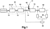
- a preferred exhaust gas after treatment system 10 depicted in Fig. 1 comprises a diesel particulate filter unit (DPFU) 60 arranged downstream of a diesel engine 12 and a NO x reducing unit 70 such as preferably a selective-catalytic-reduction (SCR) arrangement arranged downstream of said DPFU 60, wherein an injector 62 is provided for feeding reducing agent such as ammonia or urea into the exhaust gas and arranged downstream of said DPFU 60 and upstream said SCR catalyst. Downstream said SCR 70 is provided a clean up catalyst 80.
- the DPFU 60 comprises an oxidation catalyst stage (DOCS) 20, e.g.
- DOCS oxidation catalyst stage
- DOC oxidation catalyst
- DPF diesel particulate filter
- the DPF 64 can exhibit an oxidizing catalytic coating which can replace the DOC 22 as oxidation stage 20 or which can at least support the DOC 22.
- the clean-up catalyst 80 is used to clean-up excess of ammonia by reaction (R1). Partial oxidation of ammonia, given by reactions (R2) and (R3), may produce nitrous oxide (N 2 O) or elemental nitrogen, respectively. Complete oxidation of ammonia, expressed by reaction (R4), generates nitric oxide (NO).
- the catalyst consists of a metal oxide and some noble metal and could be coated on a similar structure as the SCR catalyst or on even on the same structure.
- a second NOx sensor 76 is provided between the SCR 70 and the clean up catalyst 80.
- a first NOx sensor 86 is provided downstream the clean up catalyst 80.
- the second NOx sensor 76 measures the NOx coming from the SCR 70.
- the first NOx sensor 86 measures the NOx coming from the SCR 70 and possibly the NOx created by the clean up catalyst 80.
- a control unit 90 compares the NOx values from the second NOx sensor 76 with the NOx values from the first NOx sensor 86. If the first NOx sensor 86 has detected a higher NOx content in the exhaust gases than the second NOx sensor 76 it is an indication that the clean up catalyst has transformed urea slip in the exhaust gases into NOx detected by said first NOx sensor 86.
- this first NOx sensor 86 is in fact detecting a higher NOx value than the second NOx sensor 76, a signal is sent the the urea injector 62 to decrease the urea injection by a predetermined amount.
- the feed back signal from the control unit to the urea injector may ensure that the correct amount of urea is injected to the SCR regardless of its storage capacity, operating conditions, deterioration of system performance and/or its age and at the same time keep the NOx levels at a low level.
- This feed back loop may significantly reduce the need for continuous calibration of the SCR system since it is selfcalibrated by said feed back signal from the control unit to the urea injector.
- the inventive method may also be used as a detection method of a malfunctioning and/or poisoned SCR. If abnormal amount of NOx is created by the clean up catalyst then one may suspect that the SCR system is not performing as it should.
- the amount of urea may be adjusted by sending a steering signal from the control unit 90 to the urea injector 62 which may decrease the opening time of the urea injector, decrease the frequency of a pulsated injection or a combination of said methods or any other well known method of adjusting the amount of an injector.
- a look up table may be used in order to determine the degree of reduced urea amount related to the difference in NOx measured by the first NOx sensor and the second NOx sensor.
- This table may comprise predetermined amounts of reduced urea injections corresponding to detected differences by said NOx sensors, i.e., a detected ⁇ NOx may correspond to a predetermined decreased amount of urea injection.
- the use of a first and a second NOx sensor after the SCR may result in increased robustness of tail pipe NOx control and assist in OBD (On Board Diagnosis) functions.
- the first and second NOx sensor may also significantly increase the accuracy of the estimation of NH3 storage in the SCR. Hence, the need for continuous calibration of the SCR buffer models may be reduced.
- the first and second NOx sensors also have the ability to detect ammonia slip. Hence, a more accurate and self adjusted urea injection for aged and reduced performance SCR catalyst may be accomplished while at the same time maintaining low NOx.
- Said urea amount may also be reduced in predetermined increments until the NOx measured by said first NOx sensor 86 subtracted by the NOx measured by the second NOx sensor 76 is smaller than a predetermined ⁇ NOx.
- the predetermined increments may be equal increments or larger in the beginning of the reduction than in the end of said reduction.
- the DOCS 20, i.e. the DOC 22 and/or the catalytic coating of the DPF 64, is preferably used to generate a sufficient amount of NO 2 for passive oxidation of soot trapped in the DPF 64 according to the reaction (R5) NO+NO 2 ⁇ NO 2 .
- the main function of the DPF 64 is to trap particulate matter such as soot and ashes contained in the exhaust gas.
- a typical vehicular exhaust aftertreatment system 10 requires one to several 100 000 km driving to fill the DPF 64 with ashes, and the DPF 64 can be emptied from ash by demounting the DPF 64 at service.
- To fill the DPF 64 with soot requires only one to several 1000 km driving.
- the soot can be oxidized to CO 2 which can be done during operation of the vehicle.
- the DPF 64 may be beneficial to coat with a catalytically active material including the properties of an oxidation catalyst into the DPF 64.
- a catalytically active material including the properties of an oxidation catalyst into the DPF 64.
- Regeneration of the DPF 64 may be accomplished in various ways known in the art.
- NO 2 can be used for passive oxidation of the trapped soot according to the reaction is (R6) 2NO 2 +C ⁇ 2NO+CO 2 .
- the amount of NO 2 in the exhaust gas fed into the DPF 64 can be increased by the DOCS 20 by oxidation of NO to NO 2 .
- the passive oxidation of soot can keep the soot level in the DPF 64 low at exhaust temperatures above 250°C. For some engine emissions the ratio of NO x /soot is too low for oxidizing the soot by NO 2 .
- Alternative to passive oxidation of soot it can be oxidized by oxygen at high temperatures, preferably at about 600°C. This can be achieved by either providing a burner (not shown) in the exhaust aftertreatment system 10 or by adding fuel to the exhaust gas which is burnt on an oxidation catalyst (not shown) upstream of the DPF 64. Activation of the burner or adding fuel is done in a regeneration phase which has a typical duration of a few minutes and which can last as long as 30 min if necessary.
- the exhaust gas Downstream of the DPF 64 and upstream of the nitrogen-oxides reduction unit 70, by way of example an SCR catalyst, the exhaust gas contains one or more constituents as NO and NO 2 , which can be deoxidized in the SCR catalyst.
- the main task of the SCR catalyst is to reduce NO x , i.e. NO and NO 2 , with a reductant to nitrogen gas N 2 and water H 2 O.
- NO x i.e. NO and NO 2
- ammonia NH 3 reacts with NO x to form nitrogen.
- urea is injected into the exhaust gas and by the exhaust gas temperature urea is thermolyzed or hydrolyzed into NH 3 in the exhaust gas and the SCR catalyst.
- the reductant e.g. NH 3 or urea
- the efficiency of the SCR catalyst is strongly dependent on the exhaust gas temperature, the space velocity of the exhaust gas and the NO 2 /NO ratio in the exhaust gas which enters the SCR catalyst.
- reaction (R7) has the highest efficiency and is efficient from exhaust temperatures below 200°C and above.
- Reaction (a) becomes efficient at 300°C and for reaction (c) the efficiency is lower than reaction (a) on vanadium based SCR-catalyst while it is on zeolite-based catalyst more efficient than reaction (a) but not as efficient as reaction (b).
- an unfavourable competitive reaction to reaction (c) exist which is generating the greenhouse gas N 2 O: (R10) 4NO2 + 4NH 3 ⁇ 2N 2 O + 2N 2 + 6H 2 O.
- the NO 2 formation in the DOCS 20 will depend on the exhaust gas mass flow and the temperature of the DOCS 20. Besides the flow and temperature dependency, the DOC 22 and/or the catalytic coating in the DPF 64 adsorbs sulphur (S), which can be contained in the exhaust gas, at lower temperatures and releases the sulphur at temperatures above 350°C. If driving conditions let the DOCS 20 adsorb a lot of sulphur, the NO 2 formation will be poisoned.
- S sulphur
- the NO 2 content after the DPF 64 will also depend on the condition of the DPF 64.
- Sulphur is the main source to deactivate NO 2 formation on the DOC 22 and on the catalytic coating of the DPF 64. Sulphur sticks to the catalyst at lower temperatures, typically below 400°C and is released at higher temperatures (> 400°C). The actual temperatures for sulphur adsorption and desorption depend on the particular catalyst formulation.
- Sulphur is removed from the DOC 22 and/or the coated DPF 64 by heating the catalysts to above 400°C for more than 5 minutes, which can be done by injecting fuel into the exhaust or by activating a burner.
- Another source of sulphur is the lubricant oil.
- Some conditions on some catalytic materials can cause a reversible degradation of the DOCS 20 in a manner that can it be reconditioned when heated to high temperatures above e.g. 500°C for a predetermined time period, e.g. several minutes.
- the desulphatisation temperature does not degrade the SCR-catalyst and during desulphatisation the SCR-catalyst gets a temperature where it works very efficient and the influence of NO 2 /NO ratio is low.
- the description of the virtual sensor is a map or physical model of the NO 2 formation in the DOC 22 and optionally in the DPF 64 if it's coated and on the NO 2 consumption in the DPF 64.
- the sulphur dependency of the NO 2 will not be included in the model since this invention is a way of handling the sulphur effect on NO 2 (and it's hard to model also due to unknown variations of sulphur content in the fuel (low-sulphur fuel could be any thing below 10ppm in Europe for example).
- NO x conversion may be used for on-board-diagnosis of the correct function of the DOCS 20, i.e. the DOC 22 and/or the oxidizing catalytic coating of the DPF 64, if the DPF 64 is provided with such a coating.
- the NO x conversion is derived from temperature, exhaust gas mass flow and NO 2 levels in the exhaust gas.
- the NO x sensor can be a real, physical sensor or a virtual sensor wherein the NO x level is calculated based on an appropriate model described below.
- exhaust gas flow The exhaust gas flow can be measured, or derived from the measured air intake flow and the fuel amount, or from the calculated air intake flow from engine speed, intake air pressure, intake air temperature, EGR amount and volumetric efficiency of the engine.
- exhaust gas flow in oxidation catalyst The exhaust gas flow in the DOCS 20 can be measured or calculated.
- Temperature in catalyst The temperature can e.g. be measured upstream of the DOCS 20. By applying an appropriate signal filter the measured value together with the exhaust gas flow into the DOCS 20 as a parameter can represent the actual catalyst temperature. Alternatively the temperature can be calculated by using a simple heat balance.
- the parameter "sulphur adsorbed from exhaust during a second” is the sulphur content in the fuel and lubrication oil consumed during the said second multiplied with a factor, wherein the factor is between 0 and 1 and has a temperature dependency which can e.g. be derived from a map containing temperature dependent values of the factor.
- the parameter "sulphur desorbed during a second” is the sulphur content in the DOCS 20 one second before multiplied with another temperature dependent factor which can be derived in the same way as the first factor described above.
- NO 2 formation in catalyst The NO 2 formation in the DOCS 20 can be derived from interpolating in a 3-D based on the parameters exhaust gas flow, temperature in catalyst and sulphur content. It can also be calculated using a physical model with sulphur content, temperature, exhaust gas flow and oxygen concentration as input parameters.
- the model can be e.g. a specific NO 2 formation rate which is k 1 ⁇ C NO ⁇ C O2 and an NO 2 decomposition rate which is k 2 ⁇ C NO2 , where k 1 and k 2 are temperature dependent and sulphur-content dependent parameters and C is the concentration of NO, NO 2 and O 2 , respectively.
- the specific rate is integrated over the catalyst volume.
- the HC level is also an input parameter to the model, e.g. as a denominator for the specific rates (1 + K a ⁇ C HC ).
- NO 2 out from the particulate filter The amount NO 2 which is released from the DPF 64 is the difference between the amount of NO 2 fed into the DPF 64, NO 2 formed in the DPF 64 (which is zero if no catalytic layer is provided in the DPF 64 for NO 2 generation) and NO 2 consumed by soot in the DPF 64.
- NO 2 formed in the DPF 64 can be calculated in the same manner as the NO 2 formed in the DOCS 20 (see above), preferably a physical model.
- NO 2 consumed by soot in the DPF 64 is proportional to the amount of soot in the DPF 64 and can be expressed as a specific rate k 3 ⁇ C NO2 ⁇ C soot . Again, k 3 is a temperature dependent parameter and C the respective concentration of NO 2 and soot.
- the usage of a pressure drop for calculation of a soot amount in the DPF 64 can introduce some errors due to the fact that the soot characteristic is changing with time. Therefore it is preferred to use a model for calculating the soot load and use the pressure drop as a qualitative check of the model.
- an actual measured and estimated conversion of NO 2 in the DPFU 60 and conversion NO x in the SCR catalyst can be derived.
- the NO x content upstream of the nitrogen-oxides reduction unit 70 can be measured or calculated. Downstream of the nitrogen-oxides reduction unit 70 the NO x content is measured and calculated. A difference between the measured and the calculated contents indicates that a problem with the NO oxidation in the DPFU 60 has occurred.
- the NO 2 content in the exhaust gas yielding an estimated NO 2 content upstream of the nitrogen-oxides reduction unit 70 and to calculate and/or to measure an expected NO x content upstream of the nitrogen-oxides reduction unit 70. Downstream of the nitrogen-oxides reduction unit 70 the NO x content is measured and calculated.
- One or more temperatures sensors are provided at convenient locations for determining the catalysts temperatures.
- the NO x -conversion is determined based on these values and on the temperature, exhaust gas massflow and the estimated NO 2 content.
Landscapes
- Engineering & Computer Science (AREA)
- Chemical & Material Sciences (AREA)
- Chemical Kinetics & Catalysis (AREA)
- Combustion & Propulsion (AREA)
- Mechanical Engineering (AREA)
- General Engineering & Computer Science (AREA)
- Materials Engineering (AREA)
- Health & Medical Sciences (AREA)
- Toxicology (AREA)
- Exhaust Gas After Treatment (AREA)
Claims (7)
- Procédé pour un système de post-traitement des gaz d'échappement (10) d'un moteur (12) comprenant au moins un système de réaction catalytique sélective (SCR), au moins un catalyseur de purification (80) en aval dudit SCR (70), un injecteur d'urée (62) en amont dudit SCR (70) et un premier capteur de NOx (86) en aval dudit catalyseur de purification (80), le procédé comprenant les étapes consistant :(a) à injecter une quantité prédéterminée d'urée par ledit injecteur,(b) à fournir un deuxième capteur de NOx (76) entre ledit SCR (70) et ledit catalyseur de purification (80),(c) à mesurer la teneur en NOx reçue par ledit premier capteur de NOx (86),(d) à mesurer la teneur en NOx reçue par ledit deuxième capteur de NOx (76),(e) à comparer lesdites première et deuxième teneurs en NOx l'une à l'autre,
caractérisé par le fait(f) de réduire la quantité prédéterminée d'urée si ledit premier capteur de NOx (86) mesure une teneur en NOx plus élevée que celle mesurée par ledit deuxième capteur de NOx (76). - Procédé selon la revendication 1, comprenant en outre une table de conversion ayant une quantité d'urée réduite liée à la différence de teneur en NOx mesurée par le premier capteur de NOx (86) et le deuxième capteur de NOx (76).
- Procédé selon la revendication 1, dans lequel ladite quantité d'urée est réduite par incréments prédéterminés jusqu'à ce que la teneur en NOx mesurée par ledit premier capteur de NOx (86) soustraite par la teneur en NOx mesurée par le deuxième capteur de NOx (76) soit inférieure à une ΔNOx prédéterminée.
- Utilisation du procédé selon l'une quelconque des revendications 1 à 3 pour compenser le vieillissement et/ou la détérioration de la performance du système de post-traitement des gaz d'échappement.
- Utilisation du procédé selon l'une quelconque des revendications 1 à 3 pour détecter un dysfonctionnement et/ou un empoisonnement du SCR (70).
- Utilisation du procédé selon l'une quelconque des revendications 1 à 3 pour estimer la capacité de stockage d'ammoniac dans le SCR (70).
- Système de post-traitement des gaz d'échappement comprenant au moins un système de réaction catalytique sélective (SCR (70)), au moins un catalyseur de purification (80) en aval dudit SCR (70), un injecteur d'urée (62) en amont dudit SCR (70), un premier capteur de NOx (86) en aval dudit catalyseur de purification (80) et un deuxième capteur de NOx (76) prévu entre ledit SCR (70) et ledit catalyseur de purification (80), ledit système de post-traitement des gaz d'échappement comprenant en outre une unité de commande (90) pour comparer les valeurs de NOx détectées dans lesdits premier et deuxième capteurs de NOx (86, 76), où ladite unité de commande comprend en outre des moyens pour réguler la quantité d'urée injectée par ledit injecteur d'urée (62) où ladite quantité d'urée dépend des valeurs de NOx provenant desdits premier et deuxième capteurs de NOx (86, 76), caractérisé en ce que ladite unité de commande (90) est adaptée pour envoyer un signal à l'injecteur d'urée (62) pour diminuer l'injection d'urée d'une quantité prédéterminée si le premier capteur de NOx (86) détecte une valeur de NOx plus élevée que celle détectée par le deuxième capteur de NOx (76).
Applications Claiming Priority (1)
| Application Number | Priority Date | Filing Date | Title |
|---|---|---|---|
| PCT/SE2008/000697 WO2010068147A1 (fr) | 2008-12-12 | 2008-12-12 | Système de commande scr en boucle fermée |
Publications (3)
| Publication Number | Publication Date |
|---|---|
| EP2376750A1 EP2376750A1 (fr) | 2011-10-19 |
| EP2376750A4 EP2376750A4 (fr) | 2015-05-27 |
| EP2376750B1 true EP2376750B1 (fr) | 2018-10-03 |
Family
ID=42242941
Family Applications (1)
| Application Number | Title | Priority Date | Filing Date |
|---|---|---|---|
| EP08878782.5A Active EP2376750B1 (fr) | 2008-12-12 | 2008-12-12 | Système de commande scr en boucle fermée |
Country Status (3)
| Country | Link |
|---|---|
| US (1) | US8893476B2 (fr) |
| EP (1) | EP2376750B1 (fr) |
| WO (1) | WO2010068147A1 (fr) |
Families Citing this family (18)
| Publication number | Priority date | Publication date | Assignee | Title |
|---|---|---|---|---|
| DE102009022882B4 (de) * | 2009-05-27 | 2025-08-28 | Bayerische Motoren Werke Aktiengesellschaft | Sensor zum Erfassen der Menge eines Reduktionsmittels und der Menge eines Schadstoffs in einem Abgas |
| JP5759476B2 (ja) * | 2009-12-18 | 2015-08-05 | ボルボ ラストバグナー アーベー | 排気ガス後処理デバイス内の還元剤貯蔵・レベルをコントロールするための方法 |
| US8869512B2 (en) | 2011-04-06 | 2014-10-28 | Commins Inc. | Combined engine out NOX management |
| US20130000276A1 (en) * | 2011-06-30 | 2013-01-03 | Caterpillar Inc. | Virtual reductant quality sensor |
| DE102012201749B4 (de) * | 2012-02-07 | 2024-02-15 | Robert Bosch Gmbh | Verfahren zur Überwachung eines SCR-Katalysators |
| BR112014025210B1 (pt) | 2012-04-10 | 2021-11-23 | Volvo Lastvagnar Ab | Método de auto diagnóstico para diagnóstico de um sistema de redução catalítica seletiva scr |
| SE538378C2 (sv) * | 2012-05-03 | 2016-06-07 | Scania Cv Ab | Metod för detektering av svavelförgiftning i ett avgasefterbehandlingssystem |
| US9845716B2 (en) | 2014-02-13 | 2017-12-19 | Cummins Inc. | Techniques for control of an SCR aftertreatment system |
| US9261002B2 (en) | 2014-06-11 | 2016-02-16 | Cummins Inc. | Feed-back for closed-loop selective catalytic reduction control |
| US9909517B2 (en) | 2015-11-23 | 2018-03-06 | Cummins Inc. | Mult-mode controls for engines systems including SCR aftertreatment |
| US10215072B2 (en) * | 2017-03-23 | 2019-02-26 | GM Global Technology Operations LLC | Methods for controlling and detecting catalyst poisoning of selective catalytic reduction devices |
| FR3069574B1 (fr) | 2017-07-25 | 2019-08-02 | Continental Automotive France | Procede d'adaptation d'une quantite d'agent reducteur pour une depollution en oxydes d'azote des gaz dans une ligne d'echappement de moteur |
| DE102018104385A1 (de) * | 2018-02-27 | 2018-05-03 | FEV Europe GmbH | Verfahren zur Überwachung eines Ammoniak-Schlupf-Katalysators |
| CN108868981B (zh) * | 2018-06-29 | 2019-12-10 | 潍柴动力股份有限公司 | 一种检测系统及方法 |
| SE1950598A1 (en) * | 2019-05-20 | 2020-09-29 | Scania Cv Ab | Exhaust gas aftertreatment system |
| CN114658521B (zh) * | 2020-12-23 | 2023-03-07 | 北汽福田汽车股份有限公司 | 柴油车的控制方法和装置、柴油车 |
| CN114961956B (zh) * | 2022-07-06 | 2023-12-15 | 潍柴动力股份有限公司 | 一种选择性催化还原转化效率诊断方法及装置 |
| EP4610476A1 (fr) * | 2024-02-27 | 2025-09-03 | Volvo Truck Corporation | Dispositif de catalyseur de glissement d'ammoniac et procédé de commande d'injection d'urée |
Family Cites Families (6)
| Publication number | Priority date | Publication date | Assignee | Title |
|---|---|---|---|---|
| GB9802504D0 (en) * | 1998-02-06 | 1998-04-01 | Johnson Matthey Plc | Improvements in emission control |
| DE10100420A1 (de) | 2001-01-08 | 2002-07-11 | Bosch Gmbh Robert | Verfahren und Vorrichtung zur Steuerung eines Abgasnachbehandlungssystems |
| DE10126456B4 (de) * | 2001-05-31 | 2004-05-19 | Daimlerchrysler Ag | Vorrichtung und Verfahren zur Entfernung von Stickoxiden aus dem Abgas mager betriebener Brennkraftmaschinen |
| JP4290109B2 (ja) | 2004-10-29 | 2009-07-01 | 日産ディーゼル工業株式会社 | 排気浄化装置 |
| US7562522B2 (en) * | 2006-06-06 | 2009-07-21 | Eaton Corporation | Enhanced hybrid de-NOx system |
| JP4706659B2 (ja) * | 2007-04-05 | 2011-06-22 | トヨタ自動車株式会社 | アンモニア酸化触媒におけるn2o生成量推定方法および内燃機関の排気浄化システム |
-
2008
- 2008-12-12 EP EP08878782.5A patent/EP2376750B1/fr active Active
- 2008-12-12 US US13/139,303 patent/US8893476B2/en active Active
- 2008-12-12 WO PCT/SE2008/000697 patent/WO2010068147A1/fr not_active Ceased
Non-Patent Citations (1)
| Title |
|---|
| None * |
Also Published As
| Publication number | Publication date |
|---|---|
| WO2010068147A1 (fr) | 2010-06-17 |
| EP2376750A4 (fr) | 2015-05-27 |
| US20120137657A1 (en) | 2012-06-07 |
| EP2376750A1 (fr) | 2011-10-19 |
| US8893476B2 (en) | 2014-11-25 |
Similar Documents
| Publication | Publication Date | Title |
|---|---|---|
| EP2376750B1 (fr) | Système de commande scr en boucle fermée | |
| EP2126306B1 (fr) | Procédé et système de diagnostic embarqué pour un système de post-traitement de gaz d'échappement | |
| JP5552488B2 (ja) | Scr触媒コンバータとその上流側に取付けられた酸化触媒作用のある排ガス浄化コンポーネントを備えた排ガス浄化装置を作動させるための方法 | |
| US7950224B2 (en) | Method for controlling exhaust gas purification system | |
| CN102465742B (zh) | 用于预测NOx量的方法以及使用该方法的排放系统 | |
| KR102059602B1 (ko) | 자동차의 선택적 촉매 환원 시스템을 진단하기 위한 시스템 및 방법 | |
| US8191413B2 (en) | Method for determining the nitrogen dioxide concentration in exhaust gases | |
| JP5759476B2 (ja) | 排気ガス後処理デバイス内の還元剤貯蔵・レベルをコントロールするための方法 | |
| US20100107610A1 (en) | Exhaust System for an Internal Combustion Engine | |
| CN101278110A (zh) | 用于排气后处理系统的诊断方法 | |
| EP2460999B1 (fr) | Procédé pour prédire un SOx stocké au niveau du catalyseur de DeNOx et système d'échappement l'utilisant | |
| US9234474B2 (en) | Control oriented model for LNT regeneration | |
| CN108661755B (zh) | 烟尘模型可配置校正块(ccb)控制系统 | |
| US8682595B2 (en) | Method to estimate NO2 concentration in an exhaust gas of an internal combustion engine | |
| CN120265865A (zh) | 包括氢内燃发动机和后处理系统的系统 | |
| CN113544365B (zh) | 用于调节颗粒过滤器装载的方法 | |
| CN105378243B (zh) | 用于运行驱动装置的方法以及相应的驱动装置 | |
| US10947885B2 (en) | Passive nitric oxide storage catalyst management | |
| KR20160051369A (ko) | Scr 시스템의 고장진단방법 및 장치 | |
| JP2023140571A (ja) | 排気浄化装置 | |
| JP2021050605A (ja) | 排気浄化装置 |
Legal Events
| Date | Code | Title | Description |
|---|---|---|---|
| PUAI | Public reference made under article 153(3) epc to a published international application that has entered the european phase |
Free format text: ORIGINAL CODE: 0009012 |
|
| 17P | Request for examination filed |
Effective date: 20110712 |
|
| AK | Designated contracting states |
Kind code of ref document: A1 Designated state(s): AT BE BG CH CY CZ DE DK EE ES FI FR GB GR HR HU IE IS IT LI LT LU LV MC MT NL NO PL PT RO SE SI SK TR |
|
| DAX | Request for extension of the european patent (deleted) | ||
| RA4 | Supplementary search report drawn up and despatched (corrected) |
Effective date: 20150423 |
|
| RIC1 | Information provided on ipc code assigned before grant |
Ipc: F01N 3/035 20060101ALI20150417BHEP Ipc: F01N 3/10 20060101ALI20150417BHEP Ipc: F01N 13/00 20100101ALI20150417BHEP Ipc: F01N 3/20 20060101AFI20150417BHEP Ipc: F01N 11/00 20060101ALI20150417BHEP |
|
| GRAP | Despatch of communication of intention to grant a patent |
Free format text: ORIGINAL CODE: EPIDOSNIGR1 |
|
| RIC1 | Information provided on ipc code assigned before grant |
Ipc: F01N 3/10 20060101ALI20180227BHEP Ipc: F01N 3/20 20060101AFI20180227BHEP Ipc: F01N 3/035 20060101ALI20180227BHEP Ipc: F01N 11/00 20060101ALI20180227BHEP Ipc: F01N 13/00 20100101ALI20180227BHEP |
|
| INTG | Intention to grant announced |
Effective date: 20180321 |
|
| GRAS | Grant fee paid |
Free format text: ORIGINAL CODE: EPIDOSNIGR3 |
|
| GRAJ | Information related to disapproval of communication of intention to grant by the applicant or resumption of examination proceedings by the epo deleted |
Free format text: ORIGINAL CODE: EPIDOSDIGR1 |
|
| GRAL | Information related to payment of fee for publishing/printing deleted |
Free format text: ORIGINAL CODE: EPIDOSDIGR3 |
|
| GRAR | Information related to intention to grant a patent recorded |
Free format text: ORIGINAL CODE: EPIDOSNIGR71 |
|
| INTC | Intention to grant announced (deleted) | ||
| GRAA | (expected) grant |
Free format text: ORIGINAL CODE: 0009210 |
|
| INTG | Intention to grant announced |
Effective date: 20180823 |
|
| AK | Designated contracting states |
Kind code of ref document: B1 Designated state(s): AT BE BG CH CY CZ DE DK EE ES FI FR GB GR HR HU IE IS IT LI LT LU LV MC MT NL NO PL PT RO SE SI SK TR |
|
| REG | Reference to a national code |
Ref country code: GB Ref legal event code: FG4D |
|
| REG | Reference to a national code |
Ref country code: CH Ref legal event code: EP Ref country code: AT Ref legal event code: REF Ref document number: 1048842 Country of ref document: AT Kind code of ref document: T Effective date: 20181015 |
|
| REG | Reference to a national code |
Ref country code: IE Ref legal event code: FG4D Ref country code: DE Ref legal event code: R096 Ref document number: 602008057290 Country of ref document: DE |
|
| REG | Reference to a national code |
Ref country code: SE Ref legal event code: TRGR |
|
| REG | Reference to a national code |
Ref country code: NL Ref legal event code: MP Effective date: 20181003 |
|
| REG | Reference to a national code |
Ref country code: LT Ref legal event code: MG4D |
|
| REG | Reference to a national code |
Ref country code: AT Ref legal event code: MK05 Ref document number: 1048842 Country of ref document: AT Kind code of ref document: T Effective date: 20181003 |
|
| PG25 | Lapsed in a contracting state [announced via postgrant information from national office to epo] |
Ref country code: NL Free format text: LAPSE BECAUSE OF FAILURE TO SUBMIT A TRANSLATION OF THE DESCRIPTION OR TO PAY THE FEE WITHIN THE PRESCRIBED TIME-LIMIT Effective date: 20181003 |
|
| PG25 | Lapsed in a contracting state [announced via postgrant information from national office to epo] |
Ref country code: IS Free format text: LAPSE BECAUSE OF FAILURE TO SUBMIT A TRANSLATION OF THE DESCRIPTION OR TO PAY THE FEE WITHIN THE PRESCRIBED TIME-LIMIT Effective date: 20190203 Ref country code: FI Free format text: LAPSE BECAUSE OF FAILURE TO SUBMIT A TRANSLATION OF THE DESCRIPTION OR TO PAY THE FEE WITHIN THE PRESCRIBED TIME-LIMIT Effective date: 20181003 Ref country code: BG Free format text: LAPSE BECAUSE OF FAILURE TO SUBMIT A TRANSLATION OF THE DESCRIPTION OR TO PAY THE FEE WITHIN THE PRESCRIBED TIME-LIMIT Effective date: 20190103 Ref country code: HR Free format text: LAPSE BECAUSE OF FAILURE TO SUBMIT A TRANSLATION OF THE DESCRIPTION OR TO PAY THE FEE WITHIN THE PRESCRIBED TIME-LIMIT Effective date: 20181003 Ref country code: PL Free format text: LAPSE BECAUSE OF FAILURE TO SUBMIT A TRANSLATION OF THE DESCRIPTION OR TO PAY THE FEE WITHIN THE PRESCRIBED TIME-LIMIT Effective date: 20181003 Ref country code: LV Free format text: LAPSE BECAUSE OF FAILURE TO SUBMIT A TRANSLATION OF THE DESCRIPTION OR TO PAY THE FEE WITHIN THE PRESCRIBED TIME-LIMIT Effective date: 20181003 Ref country code: ES Free format text: LAPSE BECAUSE OF FAILURE TO SUBMIT A TRANSLATION OF THE DESCRIPTION OR TO PAY THE FEE WITHIN THE PRESCRIBED TIME-LIMIT Effective date: 20181003 Ref country code: LT Free format text: LAPSE BECAUSE OF FAILURE TO SUBMIT A TRANSLATION OF THE DESCRIPTION OR TO PAY THE FEE WITHIN THE PRESCRIBED TIME-LIMIT Effective date: 20181003 Ref country code: CZ Free format text: LAPSE BECAUSE OF FAILURE TO SUBMIT A TRANSLATION OF THE DESCRIPTION OR TO PAY THE FEE WITHIN THE PRESCRIBED TIME-LIMIT Effective date: 20181003 Ref country code: AT Free format text: LAPSE BECAUSE OF FAILURE TO SUBMIT A TRANSLATION OF THE DESCRIPTION OR TO PAY THE FEE WITHIN THE PRESCRIBED TIME-LIMIT Effective date: 20181003 Ref country code: NO Free format text: LAPSE BECAUSE OF FAILURE TO SUBMIT A TRANSLATION OF THE DESCRIPTION OR TO PAY THE FEE WITHIN THE PRESCRIBED TIME-LIMIT Effective date: 20190103 |
|
| PG25 | Lapsed in a contracting state [announced via postgrant information from national office to epo] |
Ref country code: PT Free format text: LAPSE BECAUSE OF FAILURE TO SUBMIT A TRANSLATION OF THE DESCRIPTION OR TO PAY THE FEE WITHIN THE PRESCRIBED TIME-LIMIT Effective date: 20190203 Ref country code: GR Free format text: LAPSE BECAUSE OF FAILURE TO SUBMIT A TRANSLATION OF THE DESCRIPTION OR TO PAY THE FEE WITHIN THE PRESCRIBED TIME-LIMIT Effective date: 20190104 |
|
| REG | Reference to a national code |
Ref country code: DE Ref legal event code: R097 Ref document number: 602008057290 Country of ref document: DE |
|
| PG25 | Lapsed in a contracting state [announced via postgrant information from national office to epo] |
Ref country code: IT Free format text: LAPSE BECAUSE OF FAILURE TO SUBMIT A TRANSLATION OF THE DESCRIPTION OR TO PAY THE FEE WITHIN THE PRESCRIBED TIME-LIMIT Effective date: 20181003 Ref country code: DK Free format text: LAPSE BECAUSE OF FAILURE TO SUBMIT A TRANSLATION OF THE DESCRIPTION OR TO PAY THE FEE WITHIN THE PRESCRIBED TIME-LIMIT Effective date: 20181003 |
|
| REG | Reference to a national code |
Ref country code: CH Ref legal event code: PL |
|
| PLBE | No opposition filed within time limit |
Free format text: ORIGINAL CODE: 0009261 |
|
| STAA | Information on the status of an ep patent application or granted ep patent |
Free format text: STATUS: NO OPPOSITION FILED WITHIN TIME LIMIT |
|
| PG25 | Lapsed in a contracting state [announced via postgrant information from national office to epo] |
Ref country code: LU Free format text: LAPSE BECAUSE OF NON-PAYMENT OF DUE FEES Effective date: 20181212 Ref country code: MC Free format text: LAPSE BECAUSE OF FAILURE TO SUBMIT A TRANSLATION OF THE DESCRIPTION OR TO PAY THE FEE WITHIN THE PRESCRIBED TIME-LIMIT Effective date: 20181003 Ref country code: SK Free format text: LAPSE BECAUSE OF FAILURE TO SUBMIT A TRANSLATION OF THE DESCRIPTION OR TO PAY THE FEE WITHIN THE PRESCRIBED TIME-LIMIT Effective date: 20181003 Ref country code: RO Free format text: LAPSE BECAUSE OF FAILURE TO SUBMIT A TRANSLATION OF THE DESCRIPTION OR TO PAY THE FEE WITHIN THE PRESCRIBED TIME-LIMIT Effective date: 20181003 Ref country code: EE Free format text: LAPSE BECAUSE OF FAILURE TO SUBMIT A TRANSLATION OF THE DESCRIPTION OR TO PAY THE FEE WITHIN THE PRESCRIBED TIME-LIMIT Effective date: 20181003 |
|
| 26N | No opposition filed |
Effective date: 20190704 |
|
| REG | Reference to a national code |
Ref country code: IE Ref legal event code: MM4A |
|
| GBPC | Gb: european patent ceased through non-payment of renewal fee |
Effective date: 20190103 |
|
| REG | Reference to a national code |
Ref country code: BE Ref legal event code: MM Effective date: 20181231 |
|
| PG25 | Lapsed in a contracting state [announced via postgrant information from national office to epo] |
Ref country code: IE Free format text: LAPSE BECAUSE OF NON-PAYMENT OF DUE FEES Effective date: 20181212 Ref country code: SI Free format text: LAPSE BECAUSE OF FAILURE TO SUBMIT A TRANSLATION OF THE DESCRIPTION OR TO PAY THE FEE WITHIN THE PRESCRIBED TIME-LIMIT Effective date: 20181003 |
|
| PG25 | Lapsed in a contracting state [announced via postgrant information from national office to epo] |
Ref country code: BE Free format text: LAPSE BECAUSE OF NON-PAYMENT OF DUE FEES Effective date: 20181231 |
|
| PG25 | Lapsed in a contracting state [announced via postgrant information from national office to epo] |
Ref country code: GB Free format text: LAPSE BECAUSE OF NON-PAYMENT OF DUE FEES Effective date: 20190103 Ref country code: LI Free format text: LAPSE BECAUSE OF NON-PAYMENT OF DUE FEES Effective date: 20181231 Ref country code: CH Free format text: LAPSE BECAUSE OF NON-PAYMENT OF DUE FEES Effective date: 20181231 |
|
| PG25 | Lapsed in a contracting state [announced via postgrant information from national office to epo] |
Ref country code: MT Free format text: LAPSE BECAUSE OF NON-PAYMENT OF DUE FEES Effective date: 20181212 |
|
| PG25 | Lapsed in a contracting state [announced via postgrant information from national office to epo] |
Ref country code: TR Free format text: LAPSE BECAUSE OF FAILURE TO SUBMIT A TRANSLATION OF THE DESCRIPTION OR TO PAY THE FEE WITHIN THE PRESCRIBED TIME-LIMIT Effective date: 20181003 |
|
| PG25 | Lapsed in a contracting state [announced via postgrant information from national office to epo] |
Ref country code: CY Free format text: LAPSE BECAUSE OF FAILURE TO SUBMIT A TRANSLATION OF THE DESCRIPTION OR TO PAY THE FEE WITHIN THE PRESCRIBED TIME-LIMIT Effective date: 20181003 Ref country code: HU Free format text: LAPSE BECAUSE OF FAILURE TO SUBMIT A TRANSLATION OF THE DESCRIPTION OR TO PAY THE FEE WITHIN THE PRESCRIBED TIME-LIMIT; INVALID AB INITIO Effective date: 20081212 |
|
| PGFP | Annual fee paid to national office [announced via postgrant information from national office to epo] |
Ref country code: SE Payment date: 20231222 Year of fee payment: 16 Ref country code: FR Payment date: 20231226 Year of fee payment: 16 |
|
| REG | Reference to a national code |
Ref country code: SE Ref legal event code: EUG |
|
| PG25 | Lapsed in a contracting state [announced via postgrant information from national office to epo] |
Ref country code: FR Free format text: LAPSE BECAUSE OF NON-PAYMENT OF DUE FEES Effective date: 20241231 |
|
| PGFP | Annual fee paid to national office [announced via postgrant information from national office to epo] |
Ref country code: DE Payment date: 20251229 Year of fee payment: 18 |