EP2376807B1 - Stufenloses getriebe - Google Patents
Stufenloses getriebe Download PDFInfo
- Publication number
- EP2376807B1 EP2376807B1 EP09775272.9A EP09775272A EP2376807B1 EP 2376807 B1 EP2376807 B1 EP 2376807B1 EP 09775272 A EP09775272 A EP 09775272A EP 2376807 B1 EP2376807 B1 EP 2376807B1
- Authority
- EP
- European Patent Office
- Prior art keywords
- variator
- roller
- gear
- sun
- axis
- Prior art date
- Legal status (The legal status is an assumption and is not a legal conclusion. Google has not performed a legal analysis and makes no representation as to the accuracy of the status listed.)
- Not-in-force
Links
Images


Classifications
-
- F—MECHANICAL ENGINEERING; LIGHTING; HEATING; WEAPONS; BLASTING
- F16—ENGINEERING ELEMENTS AND UNITS; GENERAL MEASURES FOR PRODUCING AND MAINTAINING EFFECTIVE FUNCTIONING OF MACHINES OR INSTALLATIONS; THERMAL INSULATION IN GENERAL
- F16H—GEARING
- F16H15/00—Gearings for conveying rotary motion with variable gear ratio, or for reversing rotary motion, by friction between rotary members
- F16H15/02—Gearings for conveying rotary motion with variable gear ratio, or for reversing rotary motion, by friction between rotary members without members having orbital motion
- F16H15/04—Gearings providing a continuous range of gear ratios
- F16H15/06—Gearings providing a continuous range of gear ratios in which a member A of uniform effective diameter mounted on a shaft may co-operate with different parts of a member B
- F16H15/32—Gearings providing a continuous range of gear ratios in which a member A of uniform effective diameter mounted on a shaft may co-operate with different parts of a member B in which the member B has a curved friction surface formed as a surface of a body of revolution generated by a curve which is neither a circular arc centered on its axis of revolution nor a straight line
- F16H15/36—Gearings providing a continuous range of gear ratios in which a member A of uniform effective diameter mounted on a shaft may co-operate with different parts of a member B in which the member B has a curved friction surface formed as a surface of a body of revolution generated by a curve which is neither a circular arc centered on its axis of revolution nor a straight line with concave friction surface, e.g. a hollow toroid surface
- F16H15/38—Gearings providing a continuous range of gear ratios in which a member A of uniform effective diameter mounted on a shaft may co-operate with different parts of a member B in which the member B has a curved friction surface formed as a surface of a body of revolution generated by a curve which is neither a circular arc centered on its axis of revolution nor a straight line with concave friction surface, e.g. a hollow toroid surface with two members B having hollow toroid surfaces opposite to each other, the member or members A being adjustably mounted between the surfaces
-
- F—MECHANICAL ENGINEERING; LIGHTING; HEATING; WEAPONS; BLASTING
- F16—ENGINEERING ELEMENTS AND UNITS; GENERAL MEASURES FOR PRODUCING AND MAINTAINING EFFECTIVE FUNCTIONING OF MACHINES OR INSTALLATIONS; THERMAL INSULATION IN GENERAL
- F16H—GEARING
- F16H63/00—Control outputs from the control unit to change-speed- or reversing-gearings for conveying rotary motion or to other devices than the final output mechanism
- F16H63/02—Final output mechanisms therefor; Actuating means for the final output mechanisms
- F16H63/04—Final output mechanisms therefor; Actuating means for the final output mechanisms a single final output mechanism being moved by a single final actuating mechanism
- F16H63/06—Final output mechanisms therefor; Actuating means for the final output mechanisms a single final output mechanism being moved by a single final actuating mechanism the final output mechanism having an indefinite number of positions
- F16H63/062—Final output mechanisms therefor; Actuating means for the final output mechanisms a single final output mechanism being moved by a single final actuating mechanism the final output mechanism having an indefinite number of positions electric or electro-mechanical actuating means
-
- F—MECHANICAL ENGINEERING; LIGHTING; HEATING; WEAPONS; BLASTING
- F16—ENGINEERING ELEMENTS AND UNITS; GENERAL MEASURES FOR PRODUCING AND MAINTAINING EFFECTIVE FUNCTIONING OF MACHINES OR INSTALLATIONS; THERMAL INSULATION IN GENERAL
- F16H—GEARING
- F16H15/00—Gearings for conveying rotary motion with variable gear ratio, or for reversing rotary motion, by friction between rotary members
- F16H15/02—Gearings for conveying rotary motion with variable gear ratio, or for reversing rotary motion, by friction between rotary members without members having orbital motion
- F16H15/04—Gearings providing a continuous range of gear ratios
- F16H15/06—Gearings providing a continuous range of gear ratios in which a member A of uniform effective diameter mounted on a shaft may co-operate with different parts of a member B
- F16H15/32—Gearings providing a continuous range of gear ratios in which a member A of uniform effective diameter mounted on a shaft may co-operate with different parts of a member B in which the member B has a curved friction surface formed as a surface of a body of revolution generated by a curve which is neither a circular arc centered on its axis of revolution nor a straight line
- F16H15/36—Gearings providing a continuous range of gear ratios in which a member A of uniform effective diameter mounted on a shaft may co-operate with different parts of a member B in which the member B has a curved friction surface formed as a surface of a body of revolution generated by a curve which is neither a circular arc centered on its axis of revolution nor a straight line with concave friction surface, e.g. a hollow toroid surface
- F16H15/38—Gearings providing a continuous range of gear ratios in which a member A of uniform effective diameter mounted on a shaft may co-operate with different parts of a member B in which the member B has a curved friction surface formed as a surface of a body of revolution generated by a curve which is neither a circular arc centered on its axis of revolution nor a straight line with concave friction surface, e.g. a hollow toroid surface with two members B having hollow toroid surfaces opposite to each other, the member or members A being adjustably mounted between the surfaces
- F16H2015/383—Gearings providing a continuous range of gear ratios in which a member A of uniform effective diameter mounted on a shaft may co-operate with different parts of a member B in which the member B has a curved friction surface formed as a surface of a body of revolution generated by a curve which is neither a circular arc centered on its axis of revolution nor a straight line with concave friction surface, e.g. a hollow toroid surface with two members B having hollow toroid surfaces opposite to each other, the member or members A being adjustably mounted between the surfaces with two or more sets of toroid gearings arranged in parallel
Definitions
- the present invention relates to rolling-traction variators of the type in which drive is transmitted from one race to another by at least one roller whose orientation is variable in accordance with changes in variator drive ratio. More specifically it concerns such a variator in which the roller is mounted upon a carrier gear which is controlled through sun and ring gears.
- variable is used herein to refer to a device which transmits rotary drive from a rotary input to a rotary output at a continuously variable variator drive ratio (the ratio of the input's speed to the output's speed). Variators are particularly, but not exclusively, applicable in motor vehicle transmission applications.
- One known form of rolling-traction type variator uses at least two co-axially mounted races having opposed faces which are shaped so that the races together form an approximately toroidal space. At least one roller is positioned in the space between the races and runs upon their shaped faces to transmit drive from one race to the other. Changes in the inclination of the roller are associated with changes in the relative speeds of the races, and hence in the variator drive ratio.
- roller inclination Some mechanism is needed to control roller inclination, and the prior art contains numerous examples. Typically such mechanisms do not act by directly applying a torque to the roller's mountings to tilt the roller. Instead, the roller is mounted in such a manner that displacing it causes it to steer itself, due to the forces exerted on it by the races, to a new inclination. The steering effect arises because the roller seeks a position in which its own axis coincides with the common axis of the variator races, since in any other condition the motion of the roller is non-parallel to that of the races in the area where they engage with each other.
- the control mechanism serves to regulate the roller's displacement.
- the displacement needed to cause the roller to steer itself is along the circumferential direction (about the common axis of the variator races) and, by allowing the rollers to tilt about an axis which is inclined to the radial plane, a relationship is established between roller displacement and roller inclination.
- An actuator is provided for urging the roller along the circumferential direction and so influencing its displacement, and correspondingly influencing the variator ratio.
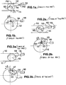
- Figures 1 to 3 are highly simplified representations of a variator viewed along the direction of the races' common axis ( Figures 1b, 2b and 3b ) and along a direction radial to said axis ( Figures 1a, 2a, 3a ).
- the variator's input and output races 111, 112 are represented in the radial views by straight lines, although in a real variator they are, as noted above, shaped to form a substantially toroidal cavity, and in the axial views they are seen to be circular.
- Roller 113 (which is one of a set, although the others are omitted from the drawings for the sake of simplicity) is arranged between the input and output races 111, 112, which are urged toward one another to provide traction between the roller and the races.
- the roller is mounted in a carriage 116 in a manner which permits the roller to rotate freely about its own axis P.
- the carriage 116 is connected to a piston of a hydraulic actuator 115. Power can in principle flow in either direction through the variator - from input to output or vice versa. Consider the case in which power flows from input to output.
- the input race 111 turns the roller 113 (its direction of rotation is indicated as w1 in the drawings) and the roller 113 drives the output race 112 (whose direction of rotation is shown as w3).
- a traction force F11 is applied to the roller 113 by the input race 111, which is driving the roller 113.
- a traction force F12 is applied to the roller by the output disc, which is driven by the roller 113.
- the sum of the traction forces F11+F12 is reacted through the hydraulic actuator 115 and must be balanced by the actuator's force.
- a momentary imbalance between the traction forces F11+F12 and the force of the actuator 115 causes the roller 113 to move.
- the force applied by the actuator 115 is reduced.
- the traction force F11+F12 will then momentarily dominate, and the roller will move toward the actuator 115, as seen in Figure 2 .
- the velocity vector V'r of the roller 113 at the region 117 where it engages the output race 112 were to remain unchanged, it would then be non-parallel to the velocity vector V'd of the surface of the output race 112 in the same region.
- the result is a traction force vector F14 acting on the roller 113 tending to cause it to tilt.
- a similar action between the input race 111 and the roller 113 produces a traction force on the roller at its region of contact (not shown) with the input race, and the two forces on the roller 113 form a couple, producing a steering effect upon the roller 113. That is, the roller 113 is caused to tilt about a steering axis 119. Note that this steering axis 119 forms a castor angle B to the radial plane 118. As a result of this castor angle, the tilting motion of the roller 113 is able to restore parallelism of the vectors V'r and V'd. The roller thus tilts (as in Figure 3b ) until it reaches a position in which the said vectors are parallel, and the aforesaid couple is thus reduced to zero. As the roller moves back and forth, its tilt (and correspondingly the variator's drive ratio) varies accordingly.
- reaction torque The total torque that must be reacted from the rollers to the variator's housing is often referred to as the "reaction torque”, and is equal to the sum of the torques upon the variator's input race 111 and output race 112. Note that this torque can only be reacted through the hydraulic actuators 115. Hence by regulating the hydraulic fluid pressures in the actuators 115, the reaction torque is directly regulated. The rollers automatically move to positions which cause the variator to generate a reaction torque corresponding to the said fluid pressures. It is thus the reaction torque that is directly regulated, and not the variator's actual drive ratio. This mode of control is thus sometimes referred to as "torque control”.
- WO2007/065900 discloses an arrangement in which a control pinion (referred to therein as a planet) is coupled to a hydraulic actuator in a manner which enables the actuator to move the pinion back and forth, but prevents the pinion from rotating. In this way the actuator controls the positions of both sun and ring gears.
- a traction force acts, and when torque transmission is effected from the roller to the output disc, a traction force (F12) acts, so, in order to support the roller it is necessary to apply a reaction force (F13) that balances these traction forces (F11 + F12). Consequently it is necessary to apply a reaction force to the power roller through the sun gear, ring gear and hydraulic servos.
- An object of the present invention is to provide a variator of the aforementioned type, having sun and ring gears and a carrier gear on which the roller is mounted, in which the means used to drive the sun and ring are not required to react the variator reaction torque.
- a variator comprising a housing, a pair of semi-toroidally recessed races each mounted to the housing for rotation about a variator axis, and a roller mounted between the races to transfer drive between them at a variable drive ratio, the variator further comprising:
- a variator (2) comprising:
- the rotational drive means consists of a motor (29).
- the rotation and inclination support part (31) has:
- the variator 2 seen in Figures 4 and 5 is of double cavity, full toroidal type. It may be used in a motor vehicle transmission, and in this context it may be combined with a known type of planetary gear (not depicted herein) to provide both forward and reverse drive, and in suitable cases to provide two or more "regimes" - i.e. two or more different transmission ratio ranges.
- the variator 2 has a pair of input races 11 mounted upon an input shaft 3 to rotate along with it.
- the input shaft 3 forms the variator's rotary input in this embodiment and may for example be coupled through suitable gearing to a source of rotary drive such as an internal combustion engine.
- An output race 12 is connected at its outer periphery to an output member 16 which forms the variator's output and may for example be coupled to gearing leading to the wheels of a motor vehicle.
- Roller units 5 (see Figure 6 ), to be described in detail later, each comprise a roller 14 that is arranged between one of the input races 11 and the output race 12.
- Each of the input races 11 has a semi-toroidally recessed surface upon which the associated rollers 14 run.
- the output race 12 has two semi-toroidally recessed faces so that the races together form two generally toroidal cavities containing the rollers 14.
- Figure 4 shows only a single roller 14 in each cavity, but in practice a plurality of rollers 14 (for example three power rollers in each cavity) are arranged at regular intervals about the cavities' circumferences.
- a hydraulic actuator 8 which acts upon one of the input races 11, urging it along the input shaft 3 toward the other races.
- the other of the input races 11 is prevented from moving along the shaft 3, so that the force of the actuator 8 is transmitted through the rollers 14 and the output race 12 to the shaft 3.
- a roller control device 4 controls the inclination of the rollers 14.
- continuous (stepless) variation of the variator drive ratio can be achieved by alteration of the radii at which the rollers 14 engage with the input discs 11 and the output disc 12.
- the output disc 12 rotates in the opposite direction to the input discs 11, so the variator drive ratio is negative.
- the roller control device 4 is formed as follows. Sun gears 25A, 25B are arranged circumferentially inwards of the respective rollers 14, being supported in a freely rotatable fashion on the input shaft 3 and linked by a sleeve member 25a passing through the output race 12, so that the sun gears 25A, 25B rotate together. Ring gears 26A, 26B are arranged circumferentially outwards of the respective rollers 14 and supported in a freely rotatable fashion with respect to the input shaft 3.
- a pinion mounting part 28 is fixed with respect to the transmission casing 6 and supports in a freely rotatable fashion control pinions 27 that are arranged between the sun gears 25A, 25B and the ring gears 26A, 26B, to mesh with both.
- the roller control device 4 includes the roller units 5 referred to above and a motor unit 29 (see Figure 5 ) constituting a rotary drive means that drives the ring gear 26A in rotation.
- the carrier 28 comprises a front main carrier plate 28a, a front subcarrier plate 28b, a rear subcarrier plate 28c, and a rear main carrier plate 28d.
- the front main carrier plate 28a is formed on its circumferentially inward side with a sleeve 28g.
- the sleeve 28g is supported in a freely rotatable fashion on the input shaft 3 by means of a bearing 43.
- the front main carrier plate 28a is formed on its circumferentially outward side with a connecting part 28s.
- the connecting part 28s is fixed to the inside face of the transmission casing 6.
- the front main carrier plate 28a is integrally formed with pinion shafts 28e. Control pinions 27, to be described, are supported thereon in a freely rotatable fashion by means of bearings 41.
- the front subcarrier plate 28b is formed with holes 28h into which are fitted projections 28f that are formed on the pinion shafts 28e, and is thereby fixed with respect to the main carrier plate 28a by means of the holes 28h. Also, the front subcarrier plate 28b is formed with a sleeve 28i on the circumferentially inward side thereof and is arranged so as to be on the circumferentially outward side of the sleeve member 25a.
- the rear main carrier plate 28d is formed with a sleeve 28m on the circumferentially inward side thereof.
- the sleeve 28m is supported in a freely rotatable fashion on the input shaft 3 by means of a bearing 44.
- pinion shafts 28j are integrally formed on the rear main carrier plate 28d and the control pinions 27 are supported in a freely rotatable fashion thereon by means of bearings 42.
- the rear subcarrier plate 28c is formed with holes 281 into which are fitted projections 28k that are formed on the pinion shaft 28j and is thereby fixed with respect to the rear main carrier plate 28d by means of the holes 281.
- the rear subcarrier plate 28c is formed on its circumferentially inward side with a sleeve 28n arranged so as to be on the circumferentially outward side of the sleeve member 25a.
- the front subcarrier plate 28b and the rear subcarrier plate 28c are linked on the circumferentially inward side of the output disc 12 and in this way the carrier 28, which is constituted by the front main carrier plate 20a, the front subcarrier plate 28b, the rear subcarrier plate 28c and the rear main carrier plate 28d, is fixed with respect to the transmission casing 6. Also, at the portion where the front subcarrier plate 28b and the rear subcarrier plate 28c are linked, the output disc 12 is supported in a freely rotatable fashion by means of bearings 45.
- control pinions 27 on the left side of Figure 4 are arranged between adjacent power rollers 14 in the cavity 13 and mesh with the sun gear 25A and the ring gear 26A. They are supported in a freely rotatable fashion by means of the bearings 41, on the pinion shafts 28e that are integrally formed with the carrier 28.
- control pinions 27 on the right side of Figure 4 are arranged between adjacent rollers 14 in the cavity 13 and mesh with the sun gear 25B and the ring gear 26B. They are supported in a freely rotatable fashion by means of the bearings 42, 42 on the pinion shaft 28j that is integrally formed with the carrier 28.
- roller units 5 are arranged in the two cavities (three per cavity). All of the roller units 5 are constructed in the same way.
- the roller units 5 have a shape in which the range of movement of the aforesaid power roller 14 is cut out from an annular gear, and comprise: a planet gear 33 whose circumferentially inward side (the lower side in Figure 4 ) meshes with the sun gear 25A (25B) and whose circumferentially outward side (the upper side in Figure 4 ) meshes with the ring gear 26A (26B); and a rotation and inclination support part 31 that is fixed and supported by the central portion of this planet gear 33 and supports the power rollers 14 in freely rotatable fashion in the ⁇ 1 direction and with freedom to incline in the ⁇ 2 direction.
- the rotation and inclination support part 31 comprises a central support part 35 and roller rotation support part 37.
- This central support part 35 is integrally formed with a support shaft 32 and is formed in cylindrical shape centred on an axis (the first axis) I that is inclined by a caster angle ⁇ in a plane orthogonal to the support shaft 32 from an axis H parallel with the two discs 11, 12 and orthogonal to this support shaft 32.
- the roller rotational support part 37 is formed in a cylindrical shape centred on an axis (the second axis) J constituting the axis of rotation of the power roller 14 and orthogonal to the above-mentioned axis I, and is supported in a freely rotatable fashion with respect to the cylindrically shaped arcuate surface 36 of this central support part 35. Also, the roller rotational support part 35 supports in a freely rotatable fashion a roller 14 that rotates about the axis J, by means of a cylindrical arcuate surface 38 thereof.
- the motor unit 29 is arranged below the variator 2 within the transmission casing 6 and comprises a drive section 29a constituted by a stepping motor, and a rack 29b.
- a drive section 29a constituted by a stepping motor
- a rack 29b In the drive section 29a there is provided a rotor (not shown) that is controlled in accordance with the operating conditions of the vehicle, based on a signal from an electronic control device, not shown.
- the rack 29b is connected with the rotor through a screw mechanism (not shown) that converts rotary motion into linear motion.
- the rack 29b is a rack-shaped member that is formed with a plurality of teeth 29c on its upper surface. The teeth 29c mesh with external teeth 26a formed on the outer circumference of the ring gear 26A.
- Figure 7(b) shows what happens when, for example, the ring gear 26A is driven in rotation by the motor unit 29 in the ⁇ 4 direction.
- the planet gear 33 of the roller units 5 is rotated in the same direction as the ring gear 26A and the control pinion 27 is rotated about the pinion shaft 28e of the carrier 28, causing the sun gear 25A that is meshed therewith to be rotated in the ⁇ 5 direction, which is the opposite direction to that of the ring gear 26A.
- the power roller units 5 are rotated in the ⁇ 4 direction from the ring gear 26A and rotated in the ⁇ 5 direction from the sun gear 25A, so that the power roller units rotate (by themselves) to their original position and the angles of the support shafts 32 of the roller units 5 are altered as shown in Figure 7(b) .
- the rollers 14 are inclined towards the rotational direction ⁇ 3 of the output disc 12 together with the roller rotational support part 37, by means of the cylindrically shaped parallel faces that are provided on the central support part 35 of the rotation and inclination support part 31.
- the balance of forces in the variator 2 will be described. Even when the variator 2 is at a fixed transmission ratio in which no transmission ratio control is being performed, a traction force F1 is generated on the rollers 14 whilst torque transmission is being performed between the input discs 11 and the output disc 12. As shown in Figure 5 , the traction force F1 can be divided into a force F2 that acts at the circumferentially outward region of the variator 2 on the planet gear 33 and a force F3 that acts on the circumferentially inward region of the variator 2 on the planet gear 33.
- the force F2 is transmitted to the ring gear 26A as a force F5 tending to rotate the ring gear 26A in the clockwise direction in Figure 5 , through the meshing of the planet gear 33 with the ring gear 26A.
- the force F5 that is transmitted to the ring gear 26A is transmitted to the control pinion 27 as a force F7 tending to rotate the control pinion 27 in the clockwise direction in Figure 5 through the meshing of ring gear 26A and the control pinion 27.
- the force F3 is transmitted to the sun gear 25A as a force F6 tending to rotate the sun gear 25A in the clockwise direction in Figure 5 , through the meshing of the planet gear 33 and the sun gear 25A.
- the force F6 that is transmitted to the sun gear 25A is transmitted to the control pinion 27 as a force F8 tending to rotate the control pinion 27 in the anticlockwise direction in Figure 5 , by meshing of the sun gear 25A with the control pinion 27.
- Forces F7 and F8 tend to rotate the control pinion 27 in mutually opposite directions, i.e. they constitute a force F9 that acts on the pinion shaft 28e, tending to move the control pinion in the clockwise direction in Figure 5 (the direction of rotation of the input discs 11).
- the force F9 acts on the transmission casing 6 (see Figure 4 ) through the carrier 28.
- Force F9 is the sum of F7 and F8, which are of the same magnitude as the forces F2, F3 that were resolved from the traction force F1 as described above, so it is of the same magnitude as the traction force F1. Furthermore, the traction forces F1 and F9 can be placed in a balanced condition (in which they do not rotate the planet gear 33 and control pinion 27) since the centre of rotation of the planet gear 33 (rollers 14) on which they respectively act, and the pinion shafts 28e are at substantially the same radius as the input discs 11. In other words, all of the traction forces F1 that are generated on the rollers 14 act on the transmission casing 6, so all of the reaction force in respect of these transmission forces F1 can be borne by the transmission casing 6.
- control pinions 27 are arranged between the rollers 14 so that no movement of the power rollers 14 in the direction of rotation of the two discs 11 and the disc 12 takes place when transmission ratio control of the roller units 5 that support the rollers 14 is performed. There is therefore no risk of fouling of the power rollers 14 and control pinions 27.
- the carrier 28, immovably mounted with respect to the transmission casing 6, supports control pinions 27 meshing with the sun gears 25A, 25B and ring gears 26A, 26B in a freely rotatable fashion. Consequently, even when a traction force F1 acts on the rollers 14, causing reaction to be transmitted through the planet gear 33 to the sun gears 25A, 25B and ring gears 26A, 26B, the reaction of the traction force F1 transmitted to the sun gears 25A, 25B and ring gears 26A, 26B is referred to the transmission casing 6 through the control pinions 27 and carrier 28.
- the traction force F1 produced by the power rollers 14 is reacted by the transmission casing 6, even when the transmission force F1 varies in accordance with unpredictable operating conditions. It therefore becomes unnecessary to perform output control of the reaction force produced by the motor unit 29 so as to track the traction force F1.
- a control mechanism for performing complicated control such as, for example, feedback control is made unnecessary and simplification and cost reduction can thus be achieved.
- the rotatary drive means is constituted by a motor, a simple construction can be adopted. Also, in particular if a stepping motor, i.e. a motor that is capable of controlling its own position in response to an electrical instruction, is employed for the motor unit 29, a device for performing feedback by detecting the position of, for example, the sun gears 25A, 25B or ring gears 26A, 26B becomes unnecessary, so the variator 2 can be simplified and costs can be reduced.
- a stepping motor i.e. a motor that is capable of controlling its own position in response to an electrical instruction
- the rotation and inclination support part 31 can incline the rollers 14 with respect to the direction of rotation of the two discs 11, 12 by means of the cylindrically shaped parallel faces of the central support part 35, when the support shaft 32 is inclined by rotational control of the planet gear 33, and can subsequently, incline the power rollers 14 and return the power rollers 14 in the tangential direction of the direction of rotation of the two discs 11, 12, in accordance with the caster angle ⁇ , by means of the cylindrically shaped arcuate surfaces 36 of the central support part 35, when these power rollers 14 are inclined in a direction with altered contact radii of the contact regions 17 by the difference in direction of rotation at the contact regions 17.
- the ring gear was driven in rotation by the rotational drive means.
- the present invention could also be applied in a construction in which the sun gear, or sun gear and ring gear are driven in rotation by the rotational drive means.
- the rotational drive means need not necessarily be a motor unit 2 having a stepping motor and screw mechanism.
- a hydraulic servo could be employed.
Landscapes
- Engineering & Computer Science (AREA)
- General Engineering & Computer Science (AREA)
- Mechanical Engineering (AREA)
- Friction Gearing (AREA)
- Transmission Devices (AREA)
- General Details Of Gearings (AREA)
Claims (7)
- Stufenloses Getriebe (2), das ein Gehäuse (6), ein Paar halbringförmig vertiefter Laufringe (11, 12), die jeder an dem Gehäuse (6) für Drehung um eine Achse des stufenlosen Getriebes angebracht werden, und eine zwischen den Laufringen (11, 12) angebrachte Laufrolle (14) umfasst, um zwischen ihnen Antrieb mit einem variablen Antriebsverhältnis zu übertragen, wobei das stufenlose Getriebe (2) des Weiteren umfasst:ein Sonnenrad (25A, 25B) zwischen den Laufringen (11, 12);ein Hohlrad (26A, 26B) zwischen den Laufringen (11,12), wobei sich das Hohlrad (26A, 26B) radial auswärts des Sonnenrads (25A, 25B) befindet, ein Tragrad (33), das zwischen dem Sonnen- (25A, 25B) und Hohlrad (26A, 26B) angeordnet wird und mit beiden ineinandergreift, und auf der Winde wird die Laufrolle (14) in einer Weise angebracht, die es der Laufrolle (14) ermöglicht, sich um ihre eigene Achse zu drehen und sich bezogen auf die Laufringe (11,12) zu neigen, um das Antriebsverhältnis zu verändern; dadurch gekennzeichnet, dass ein Steuerritzel (27), das zwischen dem Sonnen- (25A, 25B) und Hohlrad (26A, 26B) angeordnet wird und sich mit beiden verzahnt, wobei das Steuerritzel (27) an dem Gehäuse (6) in einer Weise angebracht wird, die es ihm erlaubt, sich frei um eine Ritzelachse zu drehen, aber die Ritzelachse am Bewegen bezüglich des Gehäuses (6) hindert.
- Stufenloses Getriebe (2) nach Anspruch 1, das des Weiteren einen Drehantrieb (29) zum Drehen mindestens entweder des Sonnen- (25A, 25B) oder des Hohlrads (26A, 26B) umfasst.
- Stufenloses Getriebe (2) nach Anspruch 2, in dem der Drehantrieb (29) angepasst wird, das Sonnen- (25A, 25B) und/oder Hohlrad (26A, 26B) zu einer ausgewählten Position zu bewegen.
- Stufenloses Getriebe (2) nach Anspruch 3, in dem der Drehantrieb (29) einen Schrittmotor umfasst.
- Stufenloses Getriebe (2) nach einem vorhergehenden Anspruch, in dem der Drehantrieb (29) einen Zahnstangenmechanismus umfasst.
- Stufenloses Getriebe (2) nach einem vorhergehenden Anspruch, in dem das Steuerritzel auf einem Tragteil angebracht wird, das bezüglich des Gehäuses befestigt wird.
- Stufenloses Getriebe (2) nach einem vorhergehenden Anspruch, in dem die Halterungen der Laufrolle es der Laufrolle (14) ermöglichen, sich um eine Neigungsachse zu neigen, die zu einer Ebene radial zu der Achse des stufenlosen Getriebes durch einen Nachlaufwinkel geneigt wird.
Applications Claiming Priority (2)
| Application Number | Priority Date | Filing Date | Title |
|---|---|---|---|
| JP2008319493A JP2010144743A (ja) | 2008-12-16 | 2008-12-16 | 無段変速機 |
| PCT/GB2009/051723 WO2010070341A1 (en) | 2008-12-16 | 2009-12-16 | Continuously variable transmission. |
Publications (2)
| Publication Number | Publication Date |
|---|---|
| EP2376807A1 EP2376807A1 (de) | 2011-10-19 |
| EP2376807B1 true EP2376807B1 (de) | 2019-10-16 |
Family
ID=42060725
Family Applications (1)
| Application Number | Title | Priority Date | Filing Date |
|---|---|---|---|
| EP09775272.9A Not-in-force EP2376807B1 (de) | 2008-12-16 | 2009-12-16 | Stufenloses getriebe |
Country Status (5)
| Country | Link |
|---|---|
| US (1) | US9051999B2 (de) |
| EP (1) | EP2376807B1 (de) |
| JP (2) | JP2010144743A (de) |
| CN (1) | CN102483140B (de) |
| WO (1) | WO2010070341A1 (de) |
Families Citing this family (7)
| Publication number | Priority date | Publication date | Assignee | Title |
|---|---|---|---|---|
| GB201200357D0 (en) * | 2012-01-10 | 2012-02-22 | Torotrak Dev Ltd | Variator |
| GB201201068D0 (en) | 2012-01-23 | 2012-03-07 | Torotrak Dev Ltd | Variator |
| CN104321561B (zh) | 2012-04-19 | 2017-03-08 | 传输Cvt股份有限公司 | 环面驱动cvt中的滚轮位置控制 |
| GB201209265D0 (en) * | 2012-05-25 | 2012-07-04 | Univ City | Transmission system |
| WO2014125050A1 (en) * | 2013-02-13 | 2014-08-21 | Torotrak (Development) Ltd | Multi-mode transmission |
| WO2017174106A1 (en) * | 2016-04-04 | 2017-10-12 | Mazaro Nv | Planetary variator for variable transmission |
| CN110273990B (zh) * | 2019-06-06 | 2021-02-09 | 黄丹 | 一种盘齿活杆无级自动变速箱 |
Family Cites Families (7)
| Publication number | Priority date | Publication date | Assignee | Title |
|---|---|---|---|---|
| US20030083175A1 (en) * | 2001-10-30 | 2003-05-01 | Haka Raymond James | Full toroidal continuously variable unit with a high caster angle |
| GB0201628D0 (en) * | 2002-01-24 | 2002-03-13 | Torotrak Dev Ltd | Improvements relating to continuously variable transmissions |
| WO2005084987A1 (en) * | 2004-02-28 | 2005-09-15 | Naim Guendouz | Automatic gas cap actuator with redundancy |
| GB0412615D0 (en) * | 2004-06-07 | 2004-07-07 | Torotrak Dev Ltd | Variator |
| JP4506541B2 (ja) * | 2005-04-11 | 2010-07-21 | 株式会社エクォス・リサーチ | 無段変速機 |
| GB0524795D0 (en) * | 2005-12-05 | 2006-01-11 | Torotrak Dev Ltd | Variator |
| JP4830948B2 (ja) * | 2007-03-30 | 2011-12-07 | 株式会社エクォス・リサーチ | トロイダル式無段変速装置 |
-
2008
- 2008-12-16 JP JP2008319493A patent/JP2010144743A/ja active Pending
-
2009
- 2009-12-16 EP EP09775272.9A patent/EP2376807B1/de not_active Not-in-force
- 2009-12-16 WO PCT/GB2009/051723 patent/WO2010070341A1/en not_active Ceased
- 2009-12-16 US US13/139,852 patent/US9051999B2/en active Active
- 2009-12-16 CN CN200980156761.3A patent/CN102483140B/zh not_active Expired - Fee Related
- 2009-12-16 JP JP2011540222A patent/JP5643220B2/ja not_active Expired - Fee Related
Non-Patent Citations (1)
| Title |
|---|
| None * |
Also Published As
| Publication number | Publication date |
|---|---|
| US20120142483A1 (en) | 2012-06-07 |
| CN102483140A (zh) | 2012-05-30 |
| JP2010144743A (ja) | 2010-07-01 |
| JP2012514161A (ja) | 2012-06-21 |
| JP5643220B2 (ja) | 2014-12-17 |
| WO2010070341A1 (en) | 2010-06-24 |
| CN102483140B (zh) | 2016-01-20 |
| US9051999B2 (en) | 2015-06-09 |
| EP2376807A1 (de) | 2011-10-19 |
Similar Documents
| Publication | Publication Date | Title |
|---|---|---|
| EP2376807B1 (de) | Stufenloses getriebe | |
| CA2569114C (en) | Variator | |
| US8292772B2 (en) | Continuously variable toroidal transmission | |
| JP4830948B2 (ja) | トロイダル式無段変速装置 | |
| CN101365894B (zh) | 变速器 | |
| JP2019056457A (ja) | 無段変速機 | |
| JP2018001937A (ja) | ステアリング装置 | |
| KR20100065906A (ko) | 무단 변속기 | |
| KR20050091603A (ko) | 베벨기어 어셈블리를 이용한 무단변속기 | |
| JPH04224347A (ja) | 摩擦式無段変速機 | |
| KR20160027860A (ko) | 무단변속 모듈과 그것을 이용한 무단변속기 | |
| KR20130085608A (ko) | 무단 변속기 |
Legal Events
| Date | Code | Title | Description |
|---|---|---|---|
| PUAI | Public reference made under article 153(3) epc to a published international application that has entered the european phase |
Free format text: ORIGINAL CODE: 0009012 |
|
| 17P | Request for examination filed |
Effective date: 20110713 |
|
| AK | Designated contracting states |
Kind code of ref document: A1 Designated state(s): AT BE BG CH CY CZ DE DK EE ES FI FR GB GR HR HU IE IS IT LI LT LU LV MC MK MT NL NO PL PT RO SE SI SK SM TR |
|
| DAX | Request for extension of the european patent (deleted) | ||
| 19U | Interruption of proceedings before grant |
Effective date: 20171208 |
|
| 19W | Proceedings resumed before grant after interruption of proceedings |
Effective date: 20181001 |
|
| RAP1 | Party data changed (applicant data changed or rights of an application transferred) |
Owner name: ALLISON TRANSMISSION, INC. Owner name: KK EQUOS RESEARCH |
|
| GRAP | Despatch of communication of intention to grant a patent |
Free format text: ORIGINAL CODE: EPIDOSNIGR1 |
|
| STAA | Information on the status of an ep patent application or granted ep patent |
Free format text: STATUS: GRANT OF PATENT IS INTENDED |
|
| INTG | Intention to grant announced |
Effective date: 20190329 |
|
| GRAS | Grant fee paid |
Free format text: ORIGINAL CODE: EPIDOSNIGR3 |
|
| GRAJ | Information related to disapproval of communication of intention to grant by the applicant or resumption of examination proceedings by the epo deleted |
Free format text: ORIGINAL CODE: EPIDOSDIGR1 |
|
| GRAL | Information related to payment of fee for publishing/printing deleted |
Free format text: ORIGINAL CODE: EPIDOSDIGR3 |
|
| STAA | Information on the status of an ep patent application or granted ep patent |
Free format text: STATUS: REQUEST FOR EXAMINATION WAS MADE |
|
| GRAR | Information related to intention to grant a patent recorded |
Free format text: ORIGINAL CODE: EPIDOSNIGR71 |
|
| INTC | Intention to grant announced (deleted) | ||
| STAA | Information on the status of an ep patent application or granted ep patent |
Free format text: STATUS: GRANT OF PATENT IS INTENDED |
|
| GRAA | (expected) grant |
Free format text: ORIGINAL CODE: 0009210 |
|
| STAA | Information on the status of an ep patent application or granted ep patent |
Free format text: STATUS: THE PATENT HAS BEEN GRANTED |
|
| INTG | Intention to grant announced |
Effective date: 20190904 |
|
| AK | Designated contracting states |
Kind code of ref document: B1 Designated state(s): AT BE BG CH CY CZ DE DK EE ES FI FR GB GR HR HU IE IS IT LI LT LU LV MC MK MT NL NO PL PT RO SE SI SK SM TR |
|
| REG | Reference to a national code |
Ref country code: GB Ref legal event code: FG4D |
|
| REG | Reference to a national code |
Ref country code: CH Ref legal event code: EP |
|
| REG | Reference to a national code |
Ref country code: DE Ref legal event code: R096 Ref document number: 602009060164 Country of ref document: DE |
|
| REG | Reference to a national code |
Ref country code: IE Ref legal event code: FG4D |
|
| REG | Reference to a national code |
Ref country code: AT Ref legal event code: REF Ref document number: 1191591 Country of ref document: AT Kind code of ref document: T Effective date: 20191115 |
|
| REG | Reference to a national code |
Ref country code: NL Ref legal event code: MP Effective date: 20191016 |
|
| REG | Reference to a national code |
Ref country code: LT Ref legal event code: MG4D |
|
| REG | Reference to a national code |
Ref country code: AT Ref legal event code: MK05 Ref document number: 1191591 Country of ref document: AT Kind code of ref document: T Effective date: 20191016 |
|
| PG25 | Lapsed in a contracting state [announced via postgrant information from national office to epo] |
Ref country code: PL Free format text: LAPSE BECAUSE OF FAILURE TO SUBMIT A TRANSLATION OF THE DESCRIPTION OR TO PAY THE FEE WITHIN THE PRESCRIBED TIME-LIMIT Effective date: 20191016 Ref country code: LT Free format text: LAPSE BECAUSE OF FAILURE TO SUBMIT A TRANSLATION OF THE DESCRIPTION OR TO PAY THE FEE WITHIN THE PRESCRIBED TIME-LIMIT Effective date: 20191016 Ref country code: AT Free format text: LAPSE BECAUSE OF FAILURE TO SUBMIT A TRANSLATION OF THE DESCRIPTION OR TO PAY THE FEE WITHIN THE PRESCRIBED TIME-LIMIT Effective date: 20191016 Ref country code: GR Free format text: LAPSE BECAUSE OF FAILURE TO SUBMIT A TRANSLATION OF THE DESCRIPTION OR TO PAY THE FEE WITHIN THE PRESCRIBED TIME-LIMIT Effective date: 20200117 Ref country code: NO Free format text: LAPSE BECAUSE OF FAILURE TO SUBMIT A TRANSLATION OF THE DESCRIPTION OR TO PAY THE FEE WITHIN THE PRESCRIBED TIME-LIMIT Effective date: 20200116 Ref country code: ES Free format text: LAPSE BECAUSE OF FAILURE TO SUBMIT A TRANSLATION OF THE DESCRIPTION OR TO PAY THE FEE WITHIN THE PRESCRIBED TIME-LIMIT Effective date: 20191016 Ref country code: NL Free format text: LAPSE BECAUSE OF FAILURE TO SUBMIT A TRANSLATION OF THE DESCRIPTION OR TO PAY THE FEE WITHIN THE PRESCRIBED TIME-LIMIT Effective date: 20191016 Ref country code: FI Free format text: LAPSE BECAUSE OF FAILURE TO SUBMIT A TRANSLATION OF THE DESCRIPTION OR TO PAY THE FEE WITHIN THE PRESCRIBED TIME-LIMIT Effective date: 20191016 Ref country code: PT Free format text: LAPSE BECAUSE OF FAILURE TO SUBMIT A TRANSLATION OF THE DESCRIPTION OR TO PAY THE FEE WITHIN THE PRESCRIBED TIME-LIMIT Effective date: 20200217 Ref country code: LV Free format text: LAPSE BECAUSE OF FAILURE TO SUBMIT A TRANSLATION OF THE DESCRIPTION OR TO PAY THE FEE WITHIN THE PRESCRIBED TIME-LIMIT Effective date: 20191016 Ref country code: SE Free format text: LAPSE BECAUSE OF FAILURE TO SUBMIT A TRANSLATION OF THE DESCRIPTION OR TO PAY THE FEE WITHIN THE PRESCRIBED TIME-LIMIT Effective date: 20191016 Ref country code: BG Free format text: LAPSE BECAUSE OF FAILURE TO SUBMIT A TRANSLATION OF THE DESCRIPTION OR TO PAY THE FEE WITHIN THE PRESCRIBED TIME-LIMIT Effective date: 20200116 |
|
| PG25 | Lapsed in a contracting state [announced via postgrant information from national office to epo] |
Ref country code: IS Free format text: LAPSE BECAUSE OF FAILURE TO SUBMIT A TRANSLATION OF THE DESCRIPTION OR TO PAY THE FEE WITHIN THE PRESCRIBED TIME-LIMIT Effective date: 20200224 Ref country code: HR Free format text: LAPSE BECAUSE OF FAILURE TO SUBMIT A TRANSLATION OF THE DESCRIPTION OR TO PAY THE FEE WITHIN THE PRESCRIBED TIME-LIMIT Effective date: 20191016 |
|
| REG | Reference to a national code |
Ref country code: DE Ref legal event code: R097 Ref document number: 602009060164 Country of ref document: DE |
|
| PG2D | Information on lapse in contracting state deleted |
Ref country code: IS |
|
| PG25 | Lapsed in a contracting state [announced via postgrant information from national office to epo] |
Ref country code: EE Free format text: LAPSE BECAUSE OF FAILURE TO SUBMIT A TRANSLATION OF THE DESCRIPTION OR TO PAY THE FEE WITHIN THE PRESCRIBED TIME-LIMIT Effective date: 20191016 Ref country code: DK Free format text: LAPSE BECAUSE OF FAILURE TO SUBMIT A TRANSLATION OF THE DESCRIPTION OR TO PAY THE FEE WITHIN THE PRESCRIBED TIME-LIMIT Effective date: 20191016 Ref country code: RO Free format text: LAPSE BECAUSE OF FAILURE TO SUBMIT A TRANSLATION OF THE DESCRIPTION OR TO PAY THE FEE WITHIN THE PRESCRIBED TIME-LIMIT Effective date: 20191016 Ref country code: CZ Free format text: LAPSE BECAUSE OF FAILURE TO SUBMIT A TRANSLATION OF THE DESCRIPTION OR TO PAY THE FEE WITHIN THE PRESCRIBED TIME-LIMIT Effective date: 20191016 Ref country code: IS Free format text: LAPSE BECAUSE OF FAILURE TO SUBMIT A TRANSLATION OF THE DESCRIPTION OR TO PAY THE FEE WITHIN THE PRESCRIBED TIME-LIMIT Effective date: 20200216 |
|
| REG | Reference to a national code |
Ref country code: CH Ref legal event code: PL |
|
| PLBE | No opposition filed within time limit |
Free format text: ORIGINAL CODE: 0009261 |
|
| STAA | Information on the status of an ep patent application or granted ep patent |
Free format text: STATUS: NO OPPOSITION FILED WITHIN TIME LIMIT |
|
| REG | Reference to a national code |
Ref country code: BE Ref legal event code: MM Effective date: 20191231 |
|
| PG25 | Lapsed in a contracting state [announced via postgrant information from national office to epo] |
Ref country code: IT Free format text: LAPSE BECAUSE OF FAILURE TO SUBMIT A TRANSLATION OF THE DESCRIPTION OR TO PAY THE FEE WITHIN THE PRESCRIBED TIME-LIMIT Effective date: 20191016 Ref country code: SK Free format text: LAPSE BECAUSE OF FAILURE TO SUBMIT A TRANSLATION OF THE DESCRIPTION OR TO PAY THE FEE WITHIN THE PRESCRIBED TIME-LIMIT Effective date: 20191016 Ref country code: MC Free format text: LAPSE BECAUSE OF FAILURE TO SUBMIT A TRANSLATION OF THE DESCRIPTION OR TO PAY THE FEE WITHIN THE PRESCRIBED TIME-LIMIT Effective date: 20191016 Ref country code: SM Free format text: LAPSE BECAUSE OF FAILURE TO SUBMIT A TRANSLATION OF THE DESCRIPTION OR TO PAY THE FEE WITHIN THE PRESCRIBED TIME-LIMIT Effective date: 20191016 |
|
| 26N | No opposition filed |
Effective date: 20200717 |
|
| GBPC | Gb: european patent ceased through non-payment of renewal fee |
Effective date: 20200116 |
|
| PG25 | Lapsed in a contracting state [announced via postgrant information from national office to epo] |
Ref country code: GB Free format text: LAPSE BECAUSE OF NON-PAYMENT OF DUE FEES Effective date: 20200116 Ref country code: IE Free format text: LAPSE BECAUSE OF NON-PAYMENT OF DUE FEES Effective date: 20191216 Ref country code: FR Free format text: LAPSE BECAUSE OF NON-PAYMENT OF DUE FEES Effective date: 20191216 Ref country code: LU Free format text: LAPSE BECAUSE OF NON-PAYMENT OF DUE FEES Effective date: 20191216 |
|
| PG25 | Lapsed in a contracting state [announced via postgrant information from national office to epo] |
Ref country code: SI Free format text: LAPSE BECAUSE OF FAILURE TO SUBMIT A TRANSLATION OF THE DESCRIPTION OR TO PAY THE FEE WITHIN THE PRESCRIBED TIME-LIMIT Effective date: 20191016 Ref country code: BE Free format text: LAPSE BECAUSE OF NON-PAYMENT OF DUE FEES Effective date: 20191231 Ref country code: LI Free format text: LAPSE BECAUSE OF NON-PAYMENT OF DUE FEES Effective date: 20191231 Ref country code: CH Free format text: LAPSE BECAUSE OF NON-PAYMENT OF DUE FEES Effective date: 20191231 |
|
| PG25 | Lapsed in a contracting state [announced via postgrant information from national office to epo] |
Ref country code: CY Free format text: LAPSE BECAUSE OF FAILURE TO SUBMIT A TRANSLATION OF THE DESCRIPTION OR TO PAY THE FEE WITHIN THE PRESCRIBED TIME-LIMIT Effective date: 20191016 |
|
| PG25 | Lapsed in a contracting state [announced via postgrant information from national office to epo] |
Ref country code: HU Free format text: LAPSE BECAUSE OF FAILURE TO SUBMIT A TRANSLATION OF THE DESCRIPTION OR TO PAY THE FEE WITHIN THE PRESCRIBED TIME-LIMIT; INVALID AB INITIO Effective date: 20091216 Ref country code: MT Free format text: LAPSE BECAUSE OF FAILURE TO SUBMIT A TRANSLATION OF THE DESCRIPTION OR TO PAY THE FEE WITHIN THE PRESCRIBED TIME-LIMIT Effective date: 20191016 |
|
| PG25 | Lapsed in a contracting state [announced via postgrant information from national office to epo] |
Ref country code: TR Free format text: LAPSE BECAUSE OF FAILURE TO SUBMIT A TRANSLATION OF THE DESCRIPTION OR TO PAY THE FEE WITHIN THE PRESCRIBED TIME-LIMIT Effective date: 20191016 |
|
| PG25 | Lapsed in a contracting state [announced via postgrant information from national office to epo] |
Ref country code: MK Free format text: LAPSE BECAUSE OF FAILURE TO SUBMIT A TRANSLATION OF THE DESCRIPTION OR TO PAY THE FEE WITHIN THE PRESCRIBED TIME-LIMIT Effective date: 20191016 |
|
| P01 | Opt-out of the competence of the unified patent court (upc) registered |
Effective date: 20230521 |
|
| PGFP | Annual fee paid to national office [announced via postgrant information from national office to epo] |
Ref country code: DE Payment date: 20231229 Year of fee payment: 15 |
|
| REG | Reference to a national code |
Ref country code: DE Ref legal event code: R119 Ref document number: 602009060164 Country of ref document: DE |
|
| PG25 | Lapsed in a contracting state [announced via postgrant information from national office to epo] |
Ref country code: DE Free format text: LAPSE BECAUSE OF NON-PAYMENT OF DUE FEES Effective date: 20250701 |