EP2376880B1 - Verfahren und system zum detektieren kleiner mengen von substanzen - Google Patents
Verfahren und system zum detektieren kleiner mengen von substanzen Download PDFInfo
- Publication number
- EP2376880B1 EP2376880B1 EP09833742.1A EP09833742A EP2376880B1 EP 2376880 B1 EP2376880 B1 EP 2376880B1 EP 09833742 A EP09833742 A EP 09833742A EP 2376880 B1 EP2376880 B1 EP 2376880B1
- Authority
- EP
- European Patent Office
- Prior art keywords
- light
- area
- detection
- wavelength
- individual
- Prior art date
- Legal status (The legal status is an assumption and is not a legal conclusion. Google has not performed a legal analysis and makes no representation as to the accuracy of the status listed.)
- Active
Links
Images
Classifications
-
- G—PHYSICS
- G01—MEASURING; TESTING
- G01J—MEASUREMENT OF INTENSITY, VELOCITY, SPECTRAL CONTENT, POLARISATION, PHASE OR PULSE CHARACTERISTICS OF INFRARED, VISIBLE OR ULTRAVIOLET LIGHT; COLORIMETRY; RADIATION PYROMETRY
- G01J3/00—Spectrometry; Spectrophotometry; Monochromators; Measuring colours
- G01J3/02—Details
- G01J3/06—Scanning arrangements arrangements for order-selection
-
- G—PHYSICS
- G01—MEASURING; TESTING
- G01J—MEASUREMENT OF INTENSITY, VELOCITY, SPECTRAL CONTENT, POLARISATION, PHASE OR PULSE CHARACTERISTICS OF INFRARED, VISIBLE OR ULTRAVIOLET LIGHT; COLORIMETRY; RADIATION PYROMETRY
- G01J3/00—Spectrometry; Spectrophotometry; Monochromators; Measuring colours
- G01J3/28—Investigating the spectrum
- G01J3/44—Raman spectrometry; Scattering spectrometry ; Fluorescence spectrometry
-
- G—PHYSICS
- G01—MEASURING; TESTING
- G01J—MEASUREMENT OF INTENSITY, VELOCITY, SPECTRAL CONTENT, POLARISATION, PHASE OR PULSE CHARACTERISTICS OF INFRARED, VISIBLE OR ULTRAVIOLET LIGHT; COLORIMETRY; RADIATION PYROMETRY
- G01J3/00—Spectrometry; Spectrophotometry; Monochromators; Measuring colours
- G01J3/28—Investigating the spectrum
- G01J3/2803—Investigating the spectrum using photoelectric array detector
-
- G—PHYSICS
- G01—MEASURING; TESTING
- G01J—MEASUREMENT OF INTENSITY, VELOCITY, SPECTRAL CONTENT, POLARISATION, PHASE OR PULSE CHARACTERISTICS OF INFRARED, VISIBLE OR ULTRAVIOLET LIGHT; COLORIMETRY; RADIATION PYROMETRY
- G01J3/00—Spectrometry; Spectrophotometry; Monochromators; Measuring colours
- G01J3/28—Investigating the spectrum
- G01J3/30—Measuring the intensity of spectral lines directly on the spectrum itself
- G01J3/32—Investigating bands of a spectrum in sequence by a single detector
-
- G—PHYSICS
- G01—MEASURING; TESTING
- G01N—INVESTIGATING OR ANALYSING MATERIALS BY DETERMINING THEIR CHEMICAL OR PHYSICAL PROPERTIES
- G01N21/00—Investigating or analysing materials by the use of optical means, i.e. using sub-millimetre waves, infrared, visible or ultraviolet light
- G01N21/62—Systems in which the material investigated is excited whereby it emits light or causes a change in wavelength of the incident light
- G01N21/63—Systems in which the material investigated is excited whereby it emits light or causes a change in wavelength of the incident light optically excited
- G01N21/65—Raman scattering
-
- G—PHYSICS
- G01—MEASURING; TESTING
- G01N—INVESTIGATING OR ANALYSING MATERIALS BY DETERMINING THEIR CHEMICAL OR PHYSICAL PROPERTIES
- G01N21/00—Investigating or analysing materials by the use of optical means, i.e. using sub-millimetre waves, infrared, visible or ultraviolet light
- G01N21/84—Systems specially adapted for particular applications
- G01N21/88—Investigating the presence of flaws or contamination
-
- G—PHYSICS
- G01—MEASURING; TESTING
- G01N—INVESTIGATING OR ANALYSING MATERIALS BY DETERMINING THEIR CHEMICAL OR PHYSICAL PROPERTIES
- G01N33/00—Investigating or analysing materials by specific methods not covered by groups G01N1/00 - G01N31/00
- G01N33/0004—Gaseous mixtures, e.g. polluted air
- G01N33/0009—General constructional details of gas analysers, e.g. portable test equipment
- G01N33/0027—General constructional details of gas analysers, e.g. portable test equipment concerning the detector
- G01N33/0036—General constructional details of gas analysers, e.g. portable test equipment concerning the detector specially adapted to detect a particular component
- G01N33/0057—Warfare agents or explosives
-
- G—PHYSICS
- G01—MEASURING; TESTING
- G01N—INVESTIGATING OR ANALYSING MATERIALS BY DETERMINING THEIR CHEMICAL OR PHYSICAL PROPERTIES
- G01N33/00—Investigating or analysing materials by specific methods not covered by groups G01N1/00 - G01N31/00
- G01N33/22—Fuels; Explosives
- G01N33/227—Explosives, e.g. combustive properties thereof
-
- G—PHYSICS
- G01—MEASURING; TESTING
- G01N—INVESTIGATING OR ANALYSING MATERIALS BY DETERMINING THEIR CHEMICAL OR PHYSICAL PROPERTIES
- G01N21/00—Investigating or analysing materials by the use of optical means, i.e. using sub-millimetre waves, infrared, visible or ultraviolet light
- G01N21/17—Systems in which incident light is modified in accordance with the properties of the material investigated
- G01N2021/1793—Remote sensing
Definitions
- the present invention relates to detection of substances or molecules, in particular detection of very small amounts of substances or of particles of substances at stand-off distances.
- a substance e.g. an explosive substance or a controlled drug, that is hit by a laser beam will reflect or scatter most of the received light.
- the reflected and scattered light will mainly have the same wavelength as the received light, however some of the scattered light will be wavelength-shifted, this being “Raman scattered” light.
- the distribution of this scattered light comprising light of a plurality of wavelengths is called a "Raman spectrum”.
- the Raman spectrum for each substance or more precisely for each type of molecule thus, in the way similar to other spectra, comprises one or more wavelength bands/lines and is molecule-specific. Every band or line in the Raman spectrum corresponds to a vibrational mode in the molecule. Due to the unique Raman spectrum for each molecule a substance can be identified by comparing a measured Raman spectrum to reference spectra.
- a laser beam is directed at the substance and the reflected and scattered light is collected using a telescope.
- the Raman spectrum is measured using an optical filter system and an optical sensor.
- a signal processing algorithm is used to compare the measured spectrum to various spectra stored in a database.
- Remote detection can be assumed to be made at distances, these distances called stand-off distances, larger than those ordinarily in a laboratory where the substance to be examined is placed in a direct vicinity of a spectrometer, the distance generally being taken as larger than 50 cm or commonly larger than 5 m and often in the range of 10 -100 m.
- a difficult task in substance detection is to identify small amounts, also called trace amounts, of a relevant substance or a substance searched for that is located amid many other substances.
- a signal from the relevant substance is obtained together with signals from the other substances, where the latter signals can be called noise.
- SNR signal-to-noise ratio
- One such task is to identify substances present in fingerprints, where a number of other substances may also be present.
- Substances in fingerprints usually present themselves in the form of particles. Therefore, in order to maximize the SNR it is desirable to perform the detection using the area of the fingerprint where the ratio of relevant particles to irrelevant particles is as high as possible.
- the area having the largest SNR is obviously the area of one relevant particle, excluding all surrounding area. This is true not only for fingerprints, but for every application where it is desirable to detect trace amounts of substances in a cluttered environment.
- the detector used must have a near part-ide-size resolution at stand-off distances and second, the detector has to be capable of locating near particle-sized objects at stand-off distances.
- an area of detection or of interest can be divided into a plurality of smaller areas, herein called subareas, where the size of each subarea is comparable to the size of one or of a plurality of, e.g. a few such as 2 - 5 or better 2 - 3, particles. Since such a subarea will contain only one or only a few particles the SNR thereof will be high if any relevant particle is present. In extreme cases, such as for detecting special organic molecules, the subareas may even have a size comparable to the of a single or of a few molecules.
- any subarea of the larger area having one or a few relevant particles can be found.
- a laser beam is directed at a target, focusing a telescope at a place on the target illuminated by the laser beam and depicting the telescope image on a camera having several picture elements. Each picture element will then correspond to an individual element subarea on the target.
- An optical filter inserted between the telescope and the camera provides spectral information regarding the substances on the target. By repetitiously changing the band-pass wavelength of the optical filter, and collecting the response of the camera for each filter setting, the individual spectral response for each element subarea can be determined.
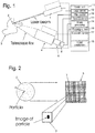
- Fig. 1 is a schematic of apparatus for standoff Raman spectroscopy, i.e. Raman spectroscopy for an object located at a relatively large distance of the device for collecting Raman scattered light.
- a monochromatic light beam is issued by a laser 1 and is directed at an area 2 or region of a target 3. When the light of the light beam hits the area, most of the light is scattered. Also, most of the scattered light has the same wavelength as the light hitting the area. However, a small fraction of the scattered light has shifted wavelengths.
- the scattered light is collected by an optical telescope 4 that is set to sharply depict the area 2 illuminated by the laser beam.
- the optical telescope obviously collects all light, including both reflected and scattered light, issued from the depicted area in the direction of the telescope, the reflected light constituting noise.
- the telescope image is depicted on the light sensitive surface 5 of a camera 6, the light sensitive surface comprising a plurality of picture elements 7, also called pixels, see Fig. 2 .
- the light sensitive surface may be called a pixel array.
- Each of the picture elements then corresponds to an individual element subarea 2' included in the illuminated area 2 of the target 3.
- Some device for obtaining spectral information about the substances in the illuminated area 3 of the target such as an optical filter 8 can be inserted between the telescope 4 and the camera 6.
- the optical filter can be the band-pass type, i.e. it can be designed to allow transmission of light only within a wavelength window.
- the size of the image of a particle may e.g. roughly be of the same magnitude as a pixel 7 and then the particle may also have a size approximately corresponding to that of the element subarea 2' that corresponds to the pixel.
- the pixel size and the stand-off distance determine the design parameters of the optical system.
- the magnification of the optical system may be determined so that the element subarea corresponding to a pixel has a size dependent on characteristics of the relevant substances and their particle size distribution, and considering the background noise, as discussed above, i.e. the contribution from irrelevant substances in the signal resulting from detection in the light sensitive surface 5 of the camera 6, the physical detection method used and the desired SNR.
- the particle size is typically in the range of 1 - 100 ⁇ m and stand-off distances can e.g. be up to 1000 m.
- the shape of the pixels 7 and the shape of the pixel array 5 may be arbitrary.
- the rectangular or square picture element and the rectangular pixel array seen in Fig, 2 represent the typical shapes found in commercial cameras, however, a single row or a single column of pixels or a non-regular or non-contiguous configuration of pixels may also be used.
- the detection method used can be ordinary Raman spectroscopy.
- Other detection methods that can be used include variations of Raman Spectroscopy, e.g. near-resonant Raman spectroscopy and resonance-enhanced Raman spectroscopy (RRS or RERS), and similar methods such as Laser-Induced Fluorescence (LIF).
- Raman Spectroscopy e.g. near-resonant Raman spectroscopy and resonance-enhanced Raman spectroscopy (RRS or RERS), and similar methods such as Laser-Induced Fluorescence (LIF).
- LIF Laser-Induced Fluorescence
- the optical filter 8 may e.g. be an LCTF (Liquid Crystal Tunable Filter) or an AOTF (Acousto-Optical Tunable Filter).
- the laser 1 can be an Nd-YAG pulsed laser but other lasers such as excimer lasers, e.g. KrF lasers, may also be used. Some applications may also use continuous-wave (CW) lasers. Some applications may require tunable lasers for e.g. fluorescence rejection and resonance enhancement.
- the relevant substances suitable to detect can include, but are not limited to explosives, explosives markers and explosives precursors.
- Other substances of interest may be TICs (Toxic Industrial Chemicals), CWAs (Chemical Warfare Agents), drugs, drug-pre-cursors and hazardous substances in general.
- non-hazardous substances indicative of a hazardous activity and/or of hazardous contents may be of interest.
- the apparatus can include a control unit 11 comprising units or modules for executing various tasks.
- a laser control module 12 can be connected to the laser 1 for controlling when light pulses are emitted and the length of the pulses.
- a camera module 13 can be connected to the camera 6 for controlling when the pixels 7 of the light sensitive surface 5 are open for detecting light and for controlling the length of their detection time periods.
- the signals from the camera can be input to an image processing unit 14 which e.g. can select the pixels, the signals from which are suited for analysis.
- a filter module 15 is connected to the optical filter 8 for controlling the filtering characteristics thereof.
- the basic procedure when searching for a specific substance or molecule in the target 3 can be as follows.
- the relevant pixel 7 may be a single pixel which corresponds to the total area 2 illuminated by the laser beam, i.e. the areas 2 and 2' may be identical. If the area 2 illuminated by the laser beam is depicted on a group of pixels 7, the signals stored for each pixel in the group can be analyzed individually or the signals from all pixels in the group can be summed for each setting of the optical filter 8 and the resulting sums can then be analyzed.
- the method can be adapted to various special cases by e.g. selecting the location of the illuminated area 2 and the shape thereof and by analyzing the signals obtained for e.g. groups of pixels 7 together with each other. Such a group of pixels then correspond to a subarea on the target 3 included in the illuminated area 2 but larger than each of the element subareas 2'. Special embodiments will now be described.
- some stabilization device or method can be used, e.g. mechanical or optical stabilization.
- image processing such as that performed in the image processing module 14 can be used to stabilize the detection.
- the laser 1 can be set to emit light pulses of e.g. the length 10 ns.
- the camera control module 13 controls the camera 6 to be open for detection only within suitably set time windows so that the pixels 7 only detect received light, i.e. taking pictures, during these time windows.
- the time windows are e.g. set to have a selected delay in relay to each issued light pulse and to have a suitably selected length to give an optimum detection of only light scattered from the illuminated subarea.
- an image stabilizing procedure can be used, e.g. executed in an image stabilization module 18, in which the taken pictures are compared to each other and if necessary displaced, so that in all the resulting pictures the signals for each pixel come from the same element subarea 2' of the object 3.
- the resulting pictures are analyzed by e.g. summing the signals for each pixel 7 of the selected subarea and each setting of the optical filter 8. These sums then constitute the measured spectrum of scattered light for the selected subarea.
- Image processing may be used to identify areas on the target which are of particular interest for detection.
- First an overview picture of the target 3 for some suitable wavelength band can be captured and thereupon the captured picture is analyzed for images of objects matching already captured pictures of objects in a built-in or externally available database, not shown. Examples of such objects include door handles, which are likely to contain trace amounts from fingerprints.
- the detector system may then be manually or automatically directed at one or more of such identified areas.
- Image processing may also be used to match patterns of detected particles to patterns in a database, not shown.
- An object of interest may first be analyzed for the existence of particles of substances, the spectra of which are included in the database. Then the location of the particles in a picture of the whole object is matched against known patterns of particle location.
- An area and/or an object can be scanned using:
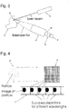
- the laser beam may be formed or shaped, e.g. by a suitable optical system, not shown, to have a cross-section having the shape of a thin bar or a thin straight line so that it illuminates a corresponding strip-shaped area 2" of the target 3, i.e. of the object of interest, see Fig. 4 .
- the width of the strip-shaped area can correspond to the width of a subarea of interest. In particular it can correspond to or possibly slightly exceed, such as not exceeding by more than 25 % or better 10 %, the width or height of an area that is depicted on a single pixel, i.e. of an element subarea 2'.
- the light sensitive surface 5 of the camera 6 may then include only a single linear array of pixels 7, i.e.
- the pixels may as in conventional cameras have a rectangular or square shape but they could also be e.g. polygonal.
- the illuminated thin line may be oriented horizontally, vertically or in an arbitrary direction.
- An area and/or an object can be scanned using a "bar-laser" as described above.
- the scanning can be made from a stationary geographical location using a detection device having pan and tilt functions as above.
- the scanning can alternatively be performed in the "moving" way described above.
- the detection device may optionally also have a pan function or a tilt function or both these functions.
- a laser beam formed to have a cross-section of a bar or a thin straight line as described above can also be used together with a conventional rectangular light sensitive surface 5 having a plurality of horizontal rows and a plurality of vertical columns of pixels 7 as seen in Fig. 4 . Then the area of the light sensitive surface 5 that corresponds to the illuminated linear area 2" on the target 3 is active for detection.
- a wavelength dispersive device 19 of an edge or linear type e.g. a cylinder-segment lens, a prism or a diffraction grating, see Fig. 3 , can be used.
- the wavelength dispersive device can be placed to deflect the collected reflected and scattered light output from the telescope 4 before it passes onto the array 5 of pixels 7.
- the wavelength dispersive device 19 will for a proper positioning deflect the light so that light of different wavelengths hits different areas of the array 5 of pixels. Then, usually light of the longest wavelengths hits a straight line of pixels at one end or side of the pixel array and light of the shortest wavelengths hits a straight line of pixels at the opposite end or side of the pixel array.
- the information or signals obtained from a row of pixels, or a column then represents/represent the intensity of light, scattered from the corresponding linear area of the target and having wavelengths only within a narrow wavelength band, i.e. the spectral response for a narrow wavelength band from the illuminated area of the target.
- a laser beam which illuminates an area 2 of the object 3 corresponding to one or more pixels 7 can be used.
- the spectrum is obtained in one measurement using spectral-spreading techniques or several measurements of one spectral band at a time.
- the beam is moved to the next subarea, that can be adjacent or non-adjacent, and another measurement is made.
- the image of the total object 3 is obtained by adding the responses from the individual subareas for which measurements have been made.
- the detection system as described herein can be used in ordinary land-based vehicles but also in un-manned vehicles, e.g. in a UAV (Unmanned Aerial Vehicle) or in a naval vehicle.
- un-manned vehicles e.g. in a UAV (Unmanned Aerial Vehicle) or in a naval vehicle.
Landscapes
- Physics & Mathematics (AREA)
- Spectroscopy & Molecular Physics (AREA)
- General Physics & Mathematics (AREA)
- Health & Medical Sciences (AREA)
- Chemical & Material Sciences (AREA)
- Life Sciences & Earth Sciences (AREA)
- Analytical Chemistry (AREA)
- Biochemistry (AREA)
- General Health & Medical Sciences (AREA)
- Immunology (AREA)
- Pathology (AREA)
- Engineering & Computer Science (AREA)
- Medicinal Chemistry (AREA)
- Food Science & Technology (AREA)
- Combustion & Propulsion (AREA)
- Nuclear Medicine, Radiotherapy & Molecular Imaging (AREA)
- Investigating, Analyzing Materials By Fluorescence Or Luminescence (AREA)
- Investigating Or Analysing Materials By Optical Means (AREA)
Claims (11)
- Verfahren zum Detektieren von Spurenmengen von Substanzen in einer unübersichtlichen Umgebung in Abrückabständen zum Bestimmen, ob ein Detektionsbereich auf einem Objekt eine gefährliche Substanz enthält, wobei der Detektionsbereich mit Licht einer definierten Wellenlänge beleuchtet und das gestreute Licht analysiert wird, um ein Raman-Spektrum oder ein ähnliches Spektrum zu erhalten, wobei das von dem Objekt gestreute Licht von einem optischen System, insbesondere einem optischen System vom Typ eines Teleskops, gesammelt und konzentriert wird, das das Bild auf einer Lichtdetektionsvorrichtung darstellt, dadurch gekennzeichnet,
dass der Abrückabstand von 10 m bis 100 m beträgt,
dass die gefährliche Substanz aus Molekülen einer bestimmten Art besteht, insbesondere aus einem Sprengstoff oder einem Bestandteil eines Sprengstoffs,
dass der Detektionsbereich in eine Vielzahl von kleineren Bereichen, den sogenannten Teilbereichen, unterteilt ist, wobei die Größe jedes Teilbereichs mit der Größe von einem oder einigen wenigen Teilchen von Molekülen der bestimmten Art vergleichbar ist,
dass eine Vielzahl von Teilbereichen gruppiert wird, um einen größeren Bereich zu bilden, und alle in der Vielzahl eingeschlossenen individuellen Teilbereiche gleichzeitig mittels des Bildes aus dem optischen System detektiert werden, das auf der Lichtdetektionsvorrichtung mit mehreren Bildelementen in einem Bildelementfeld dargestellt wird, wobei jedes Bildelement einem individuellen Teilbereich entspricht,
und
dass bei der Analyse des gestreuten Lichts die Detektionssignale von jedem der einzelnen Bildelemente einzeln analysiert werden. - Verfahren nach Anspruch 1, dadurch gekennzeichnet, dass das gesammelte Licht vor dem Detektieren gefiltert wird, so dass Licht mit nur einem Wellenlängenbereich analysiert wird.
- Verfahren nach Anspruch 2, dadurch gekennzeichnet, dass die Bandpasswellenlänge des optischen Filters wiederholt geändert wird und die Analyse des gestreuten Lichts für jeden der mehreren Wellenlängenbereiche nacheinander durchgeführt wird.
- Verfahren nach einem der Ansprüche 1-3, dadurch gekennzeichnet, dass der beleuchtete . Bereich der Oberfläche des Objekts ein Linienbereich oder ein streifenförmiger Bereich ist, insbesondere ein streifenförmiger Bereich mit einer Breite, die der Breite oder Höhe eines Bereichs entspricht oder diese etwas überschreitet, der auf einem einzelnen der einzelnen Bildelemente dargestellt ist.
- Verfahren nach Anspruch 4, dadurch gekennzeichnet, dass das gesammelte Licht durch eine Wellenlängendispersionsvorrichtung eines Kanten- oder Lineartyps mit einer Kante oder Achse geleitet wird, die ausgerichtet ist, so dass das aus dem Linienbereich gesammelte Licht auf parallele Linien der einzelnen Bildelemente trifft und das aus dem Linienbereich gesammelte Licht, das auf jede dieser Linien trifft, nur Wellenlängen eines entsprechenden individuellen Wellenlängenbandes einschließt.
- System zum Detektieren von Spurenmengen von Substanzen in einer unübersichtlichen Umgebung in Abrückabständen zum Bestimmen, ob ein Detektionsbereich auf einem Objekt eine gefährliche Substanz enthält, umfassend eine Lichtquelle zum Beleuchten des Detektionsbereichs mit Licht einer definierten Wellenlänge, ein optisches System, insbesondere ein optisches System vom Typ eines Teleskops, zum Sammeln und Konzentrieren von Licht aus dem beleuchteten Bereich der Oberfläche des Objekts, eine Lichtdetektionsvorrichtung, die gesammeltes und konzentriertes Licht empfängt, und eine Analyseeinheit zum Erhalten eines Ramanspektrums oder eines ähnlichen Spektrums aus Signalen von der Lichtdetektionsvorrichtung, dadurch gekennzeichnet, dass der Abrückabstand von 10 m bis 100 m beträgt,
dass die gefährliche Substanz aus Molekülen bestimmter Art besteht, insbesondere aus einem Sprengstoff oder einem Bestandteil eines Sprengstoffs,
dass die Lichtdetektionsvorrichtung eine lichtempfindliche Oberfläche mit einer Vielzahl von einzelnen Bildelementen umfasst, die als Bildelementfeld angeordnet sind, wobei jedes der einzelnen Bildelemente Detektionssignale bereitstellt, und
dass die Analyseeinheit dazu ausgelegt ist, den Detektionsbereich in eine Vielzahl von kleineren Bereichen, den sogenannten Teilbereichen, aufzuteilen, wobei die Größe jedes Teilbereichs mit der Größe von einem oder einigen wenigen Teilchen von Molekülen der bestimmten Art vergleichbar ist,
eine Vielzahl von Teilbereichen zu gruppieren, um einen größeren Bereich zu bilden, und gleichzeitig alle einzelnen Teilbereiche, die in der Vielzahl eingeschlossen sind, durch das Bild aus dem optischen System, das auf der Lichtdetektionsvorrichtung abgebildet ist, zu detektieren und die Detektionssignale aus jedem der einzelnen Bildelemente einzeln zu analysieren, wobei jedes Bildelement einem einzelnen Teilbereich entspricht. - System nach Anspruch 6, gekennzeichnet durch einen Filter zum Filtern des gesammelten Lichts, bevor es von der Lichtdetektionsvorrichtung empfangen wird, so dass Licht nur eines Wellenlängenbereichs detektiert wird.
- System nach Anspruch 7, dadurch gekennzeichnet, dass der Filter abstimmbar ist, so dass die Lichtdetektionsvorrichtung Licht für jeden aus einer Vielzahl von Wellenlängenbereichen nacheinander durch entsprechendes Abstimmen des Filters detektieren kann.
- System nach einem der Ansprüche 6-8, dadurch gekennzeichnet, dass die Lichtquelle so angeordnet ist, dass der beleuchtete Bereich der Oberfläche des Objekts ein Linienbereich oder ein streifenförmiger Bereich ist, insbesondere ein streifenförmiger Bereich mit einer Breite, die der Breite oder der Höhe eines Bereichs entspricht oder diese etwas überschreitet, der auf einem einzelnen des jeweiligen Bildelements abgebildet ist.
- System nach Anspruch 9, gekennzeichnet durch eine Wellenlängen-Dispersionsvorrichtung eines Kanten- oder Lineartyps, die so angeordnet ist, dass das gesammelte und konzentrierte Licht durch sie hindurch geleitet wird, wobei die Wellenlängen-Dispersionsvorrichtung ein Kanten- oder Lineartyp mit einer Kante oder Achse ist, die so ausgerichtet ist, dass das aus dem Linienbereich gesammelte Licht auf parallele Linien der einzelnen Bildelemente trifft und das aus dem Linienbereich gesammelte Licht, das auf jede dieser Linien trifft, nur Wellenlängen eines entsprechenden individuellen Wellenlängenbandes einschließt.
- System nach Anspruch 10, dadurch gekennzeichnet, dass die Wellenlängendispersionsvorrichtung eine Zylindersegmentlinse, ein Prisma oder ein Beugungsgitter ist.
Applications Claiming Priority (2)
| Application Number | Priority Date | Filing Date | Title |
|---|---|---|---|
| SE0802612A SE533454C2 (sv) | 2008-12-18 | 2008-12-18 | Detektion av små mängder av ämnen |
| PCT/SE2009/051440 WO2010071579A1 (en) | 2008-12-18 | 2009-12-17 | Detecting small amounts of substances |
Publications (3)
| Publication Number | Publication Date |
|---|---|
| EP2376880A1 EP2376880A1 (de) | 2011-10-19 |
| EP2376880A4 EP2376880A4 (de) | 2017-12-20 |
| EP2376880B1 true EP2376880B1 (de) | 2020-02-12 |
Family
ID=42269034
Family Applications (1)
| Application Number | Title | Priority Date | Filing Date |
|---|---|---|---|
| EP09833742.1A Active EP2376880B1 (de) | 2008-12-18 | 2009-12-17 | Verfahren und system zum detektieren kleiner mengen von substanzen |
Country Status (9)
| Country | Link |
|---|---|
| US (1) | US20120086939A1 (de) |
| EP (1) | EP2376880B1 (de) |
| JP (1) | JP2012513027A (de) |
| CN (1) | CN102257370A (de) |
| CA (1) | CA2745631A1 (de) |
| IL (1) | IL213267A0 (de) |
| SE (1) | SE533454C2 (de) |
| SG (1) | SG172151A1 (de) |
| WO (1) | WO2010071579A1 (de) |
Families Citing this family (11)
| Publication number | Priority date | Publication date | Assignee | Title |
|---|---|---|---|---|
| US9036142B2 (en) * | 2012-05-09 | 2015-05-19 | Seagate Technology Llc | Surface features mapping |
| CN103398990B (zh) * | 2013-07-26 | 2016-08-24 | 中国地质大学(武汉) | 一种快速识别移动目标的系统及方法 |
| US10538325B1 (en) * | 2014-11-11 | 2020-01-21 | United Services Automobile Association | Utilizing unmanned vehicles to initiate and/or facilitate claims processing |
| CN104931477A (zh) * | 2015-01-23 | 2015-09-23 | 成都鼎智汇科技有限公司 | 一种高精度拉曼光谱爆炸物识别仪 |
| CN105092485A (zh) * | 2015-08-27 | 2015-11-25 | 泉州装备制造研究所 | 危险物品检测方法和装置 |
| US10139836B2 (en) | 2016-09-27 | 2018-11-27 | International Business Machines Corporation | Autonomous aerial point of attraction highlighting for tour guides |
| EP3803293A4 (de) | 2018-05-30 | 2022-06-15 | Pendar Technologies, LLC | Verfahren und vorrichtungen zur raman-spektroskopie mit abstandsdifferenz mit erhöhter augensicherheit und verminderter explosionsgefahr |
| WO2019231512A1 (en) | 2018-05-30 | 2019-12-05 | Pendar Technologies, Llc | Methods and devices for standoff differential raman spectroscopy with increased eye safety and decreased risk of explosion |
| US11774353B2 (en) * | 2018-10-30 | 2023-10-03 | The Government Of The United States Of America, As Represented By The Secretary Of The Navy | Methods and apparatuses for biomimetic standoff detection of hazardous chemicals |
| JP7342629B2 (ja) * | 2019-11-06 | 2023-09-12 | 株式会社島津製作所 | 試料成分推定方法、試料成分推定装置、試料成分推定プログラム、学習方法および学習プログラム |
| CN112326626A (zh) * | 2020-11-06 | 2021-02-05 | 公安部第三研究所 | 一种车载扫描式路面物质激光拉曼光谱分析的探测装置 |
Family Cites Families (11)
| Publication number | Priority date | Publication date | Assignee | Title |
|---|---|---|---|---|
| CN85104863B (zh) * | 1985-06-25 | 1988-05-04 | 株式会社岛津制作所 | 状态分析的方法和装置 |
| CN1162993A (zh) * | 1994-08-20 | 1997-10-22 | 雷尼肖公司 | 爆炸物的检测器 |
| US6040906A (en) * | 1996-07-11 | 2000-03-21 | Harhay; Gregory P. | Resonance raman spectroscopy for identifying and quantitating biomatter, organic, and inorganic analytes |
| ATE514072T1 (de) * | 1997-05-05 | 2011-07-15 | Chemometec As | Verfahren zur bestimmung von teilchen in einer flüssigen probe |
| DE102004037064A1 (de) * | 2004-07-30 | 2006-02-16 | Abb Patent Gmbh | Verfahren und Einrichtung zur Funktionsprüfung eines Feldgerätes vor dessen Erstinbetriebnahme |
| GB0426993D0 (en) * | 2004-12-09 | 2005-01-12 | Council Cent Lab Res Councils | Apparatus for depth-selective raman spectroscopy |
| US7692775B2 (en) * | 2005-07-14 | 2010-04-06 | Chemimage Corporation | Time and space resolved standoff hyperspectral IED explosives LIDAR detection |
| WO2007044593A2 (en) | 2005-10-07 | 2007-04-19 | Chemimage Corporation | System and method for a chemical imaging threat assessor with a probe |
| US7796251B2 (en) * | 2006-03-22 | 2010-09-14 | Itt Manufacturing Enterprises, Inc. | Method, apparatus and system for rapid and sensitive standoff detection of surface contaminants |
| US7333190B1 (en) * | 2006-10-26 | 2008-02-19 | Itt Manufacturing Enterprises, Inc. | Raman interrogation of threat aerosols |
| GB0701477D0 (en) * | 2007-01-25 | 2007-03-07 | Renishaw Plc | Spectroscopic apparatus and methods |
-
2008
- 2008-12-18 SE SE0802612A patent/SE533454C2/sv not_active IP Right Cessation
-
2009
- 2009-12-17 EP EP09833742.1A patent/EP2376880B1/de active Active
- 2009-12-17 US US13/140,376 patent/US20120086939A1/en not_active Abandoned
- 2009-12-17 WO PCT/SE2009/051440 patent/WO2010071579A1/en not_active Ceased
- 2009-12-17 JP JP2011542067A patent/JP2012513027A/ja not_active Withdrawn
- 2009-12-17 SG SG2011043502A patent/SG172151A1/en unknown
- 2009-12-17 CN CN2009801510155A patent/CN102257370A/zh active Pending
- 2009-12-17 CA CA2745631A patent/CA2745631A1/en not_active Abandoned
-
2011
- 2011-05-31 IL IL213267A patent/IL213267A0/en unknown
Non-Patent Citations (1)
| Title |
|---|
| None * |
Also Published As
| Publication number | Publication date |
|---|---|
| CA2745631A1 (en) | 2010-06-24 |
| WO2010071579A1 (en) | 2010-06-24 |
| US20120086939A1 (en) | 2012-04-12 |
| SE0802612A1 (sv) | 2010-06-19 |
| SE533454C2 (sv) | 2010-10-05 |
| CN102257370A (zh) | 2011-11-23 |
| JP2012513027A (ja) | 2012-06-07 |
| EP2376880A1 (de) | 2011-10-19 |
| EP2376880A4 (de) | 2017-12-20 |
| IL213267A0 (en) | 2011-07-31 |
| SG172151A1 (en) | 2011-07-28 |
Similar Documents
| Publication | Publication Date | Title |
|---|---|---|
| EP2376880B1 (de) | Verfahren und system zum detektieren kleiner mengen von substanzen | |
| US8665433B2 (en) | Standoff explosives detector using deep-UV Raman spectroscopy | |
| US7692775B2 (en) | Time and space resolved standoff hyperspectral IED explosives LIDAR detection | |
| US8379193B2 (en) | SWIR targeted agile raman (STAR) system for on-the-move detection of emplace explosives | |
| US20120062697A1 (en) | Hyperspectral imaging sensor for tracking moving targets | |
| US7564546B2 (en) | Dynamic imaging of biological cells and other subjects | |
| EP2930496B1 (de) | Raman-Mikrospektrometriesystem und -verfahren zur Analyse von mikroskopischen Objekten in einer Fluidprobe | |
| US20120062740A1 (en) | Hyperspectral imaging sensor for tracking moving targets | |
| US20090219525A1 (en) | System and method for portable raman spectroscopy | |
| US20130114070A1 (en) | Targeted Agile Raman System for Detection of Unknown Materials | |
| US20120145906A1 (en) | Portable system for detecting explosives and a method of use thereof | |
| US20130135609A1 (en) | Targeted Agile Raman System for Detection of Unknown Materials | |
| US10969339B2 (en) | Optical readers | |
| DE10314424A1 (de) | Warnsystem zum Zwecke einer ortsaufgelösten Feststellung von vereisten Oberflächenstellen | |
| US8994934B1 (en) | System and method for eye safe detection of unknown targets | |
| CA3148141A1 (en) | Raman spectroscopy for minerals identification | |
| US10527552B2 (en) | Simultaneous detection of multiple spectra of scattered radiation | |
| US10495515B2 (en) | Adaptive, very high resolution imaging spectrometer | |
| Higdon et al. | Laser interrogation of surface agents (LISA) for chemical agent reconnaissance | |
| Chyba et al. | Field tests of the laser interrogation of surface agents (lisa) system for on-the-move standoff sensing of chemical agents | |
| Bar | Raman-based point and proximal detection and imaging |
Legal Events
| Date | Code | Title | Description |
|---|---|---|---|
| PUAI | Public reference made under article 153(3) epc to a published international application that has entered the european phase |
Free format text: ORIGINAL CODE: 0009012 |
|
| 17P | Request for examination filed |
Effective date: 20110711 |
|
| AK | Designated contracting states |
Kind code of ref document: A1 Designated state(s): AT BE BG CH CY CZ DE DK EE ES FI FR GB GR HR HU IE IS IT LI LT LU LV MC MK MT NL NO PL PT RO SE SI SK SM TR |
|
| DAX | Request for extension of the european patent (deleted) | ||
| RA4 | Supplementary search report drawn up and despatched (corrected) |
Effective date: 20171122 |
|
| RIC1 | Information provided on ipc code assigned before grant |
Ipc: G01N 21/88 20060101ALI20171116BHEP Ipc: G01N 21/65 20060101ALI20171116BHEP Ipc: G01J 3/06 20060101AFI20171116BHEP Ipc: G01N 33/22 20060101ALI20171116BHEP |
|
| STAA | Information on the status of an ep patent application or granted ep patent |
Free format text: STATUS: EXAMINATION IS IN PROGRESS |
|
| 17Q | First examination report despatched |
Effective date: 20190320 |
|
| REG | Reference to a national code |
Ref country code: DE Ref legal event code: R079 Ref document number: 602009061185 Country of ref document: DE Free format text: PREVIOUS MAIN CLASS: G01J0003060000 Ipc: G01J0003320000 |
|
| GRAP | Despatch of communication of intention to grant a patent |
Free format text: ORIGINAL CODE: EPIDOSNIGR1 |
|
| STAA | Information on the status of an ep patent application or granted ep patent |
Free format text: STATUS: GRANT OF PATENT IS INTENDED |
|
| RIC1 | Information provided on ipc code assigned before grant |
Ipc: G01J 3/44 20060101ALI20190613BHEP Ipc: G01N 21/65 20060101ALI20190613BHEP Ipc: G01J 3/32 20060101AFI20190613BHEP |
|
| INTG | Intention to grant announced |
Effective date: 20190717 |
|
| GRAS | Grant fee paid |
Free format text: ORIGINAL CODE: EPIDOSNIGR3 |
|
| GRAA | (expected) grant |
Free format text: ORIGINAL CODE: 0009210 |
|
| STAA | Information on the status of an ep patent application or granted ep patent |
Free format text: STATUS: THE PATENT HAS BEEN GRANTED |
|
| AK | Designated contracting states |
Kind code of ref document: B1 Designated state(s): AT BE BG CH CY CZ DE DK EE ES FI FR GB GR HR HU IE IS IT LI LT LU LV MC MK MT NL NO PL PT RO SE SI SK SM TR |
|
| REG | Reference to a national code |
Ref country code: GB Ref legal event code: FG4D |
|
| REG | Reference to a national code |
Ref country code: CH Ref legal event code: EP |
|
| REG | Reference to a national code |
Ref country code: AT Ref legal event code: REF Ref document number: 1232744 Country of ref document: AT Kind code of ref document: T Effective date: 20200215 |
|
| REG | Reference to a national code |
Ref country code: IE Ref legal event code: FG4D |
|
| REG | Reference to a national code |
Ref country code: DE Ref legal event code: R096 Ref document number: 602009061185 Country of ref document: DE |
|
| PG25 | Lapsed in a contracting state [announced via postgrant information from national office to epo] |
Ref country code: NO Free format text: LAPSE BECAUSE OF FAILURE TO SUBMIT A TRANSLATION OF THE DESCRIPTION OR TO PAY THE FEE WITHIN THE PRESCRIBED TIME-LIMIT Effective date: 20200512 Ref country code: FI Free format text: LAPSE BECAUSE OF FAILURE TO SUBMIT A TRANSLATION OF THE DESCRIPTION OR TO PAY THE FEE WITHIN THE PRESCRIBED TIME-LIMIT Effective date: 20200212 |
|
| REG | Reference to a national code |
Ref country code: LT Ref legal event code: MG4D |
|
| REG | Reference to a national code |
Ref country code: NL Ref legal event code: MP Effective date: 20200212 |
|
| PG25 | Lapsed in a contracting state [announced via postgrant information from national office to epo] |
Ref country code: HR Free format text: LAPSE BECAUSE OF FAILURE TO SUBMIT A TRANSLATION OF THE DESCRIPTION OR TO PAY THE FEE WITHIN THE PRESCRIBED TIME-LIMIT Effective date: 20200212 Ref country code: GR Free format text: LAPSE BECAUSE OF FAILURE TO SUBMIT A TRANSLATION OF THE DESCRIPTION OR TO PAY THE FEE WITHIN THE PRESCRIBED TIME-LIMIT Effective date: 20200513 Ref country code: LV Free format text: LAPSE BECAUSE OF FAILURE TO SUBMIT A TRANSLATION OF THE DESCRIPTION OR TO PAY THE FEE WITHIN THE PRESCRIBED TIME-LIMIT Effective date: 20200212 Ref country code: SE Free format text: LAPSE BECAUSE OF FAILURE TO SUBMIT A TRANSLATION OF THE DESCRIPTION OR TO PAY THE FEE WITHIN THE PRESCRIBED TIME-LIMIT Effective date: 20200212 Ref country code: IS Free format text: LAPSE BECAUSE OF FAILURE TO SUBMIT A TRANSLATION OF THE DESCRIPTION OR TO PAY THE FEE WITHIN THE PRESCRIBED TIME-LIMIT Effective date: 20200612 Ref country code: BG Free format text: LAPSE BECAUSE OF FAILURE TO SUBMIT A TRANSLATION OF THE DESCRIPTION OR TO PAY THE FEE WITHIN THE PRESCRIBED TIME-LIMIT Effective date: 20200512 |
|
| PG25 | Lapsed in a contracting state [announced via postgrant information from national office to epo] |
Ref country code: NL Free format text: LAPSE BECAUSE OF FAILURE TO SUBMIT A TRANSLATION OF THE DESCRIPTION OR TO PAY THE FEE WITHIN THE PRESCRIBED TIME-LIMIT Effective date: 20200212 |
|
| PG25 | Lapsed in a contracting state [announced via postgrant information from national office to epo] |
Ref country code: CZ Free format text: LAPSE BECAUSE OF FAILURE TO SUBMIT A TRANSLATION OF THE DESCRIPTION OR TO PAY THE FEE WITHIN THE PRESCRIBED TIME-LIMIT Effective date: 20200212 Ref country code: PT Free format text: LAPSE BECAUSE OF FAILURE TO SUBMIT A TRANSLATION OF THE DESCRIPTION OR TO PAY THE FEE WITHIN THE PRESCRIBED TIME-LIMIT Effective date: 20200705 Ref country code: RO Free format text: LAPSE BECAUSE OF FAILURE TO SUBMIT A TRANSLATION OF THE DESCRIPTION OR TO PAY THE FEE WITHIN THE PRESCRIBED TIME-LIMIT Effective date: 20200212 Ref country code: LT Free format text: LAPSE BECAUSE OF FAILURE TO SUBMIT A TRANSLATION OF THE DESCRIPTION OR TO PAY THE FEE WITHIN THE PRESCRIBED TIME-LIMIT Effective date: 20200212 Ref country code: EE Free format text: LAPSE BECAUSE OF FAILURE TO SUBMIT A TRANSLATION OF THE DESCRIPTION OR TO PAY THE FEE WITHIN THE PRESCRIBED TIME-LIMIT Effective date: 20200212 Ref country code: SM Free format text: LAPSE BECAUSE OF FAILURE TO SUBMIT A TRANSLATION OF THE DESCRIPTION OR TO PAY THE FEE WITHIN THE PRESCRIBED TIME-LIMIT Effective date: 20200212 Ref country code: SK Free format text: LAPSE BECAUSE OF FAILURE TO SUBMIT A TRANSLATION OF THE DESCRIPTION OR TO PAY THE FEE WITHIN THE PRESCRIBED TIME-LIMIT Effective date: 20200212 Ref country code: DK Free format text: LAPSE BECAUSE OF FAILURE TO SUBMIT A TRANSLATION OF THE DESCRIPTION OR TO PAY THE FEE WITHIN THE PRESCRIBED TIME-LIMIT Effective date: 20200212 Ref country code: ES Free format text: LAPSE BECAUSE OF FAILURE TO SUBMIT A TRANSLATION OF THE DESCRIPTION OR TO PAY THE FEE WITHIN THE PRESCRIBED TIME-LIMIT Effective date: 20200212 |
|
| REG | Reference to a national code |
Ref country code: DE Ref legal event code: R097 Ref document number: 602009061185 Country of ref document: DE |
|
| REG | Reference to a national code |
Ref country code: AT Ref legal event code: MK05 Ref document number: 1232744 Country of ref document: AT Kind code of ref document: T Effective date: 20200212 |
|
| PLBE | No opposition filed within time limit |
Free format text: ORIGINAL CODE: 0009261 |
|
| STAA | Information on the status of an ep patent application or granted ep patent |
Free format text: STATUS: NO OPPOSITION FILED WITHIN TIME LIMIT |
|
| 26N | No opposition filed |
Effective date: 20201113 |
|
| PG25 | Lapsed in a contracting state [announced via postgrant information from national office to epo] |
Ref country code: AT Free format text: LAPSE BECAUSE OF FAILURE TO SUBMIT A TRANSLATION OF THE DESCRIPTION OR TO PAY THE FEE WITHIN THE PRESCRIBED TIME-LIMIT Effective date: 20200212 Ref country code: IT Free format text: LAPSE BECAUSE OF FAILURE TO SUBMIT A TRANSLATION OF THE DESCRIPTION OR TO PAY THE FEE WITHIN THE PRESCRIBED TIME-LIMIT Effective date: 20200212 |
|
| PG25 | Lapsed in a contracting state [announced via postgrant information from national office to epo] |
Ref country code: PL Free format text: LAPSE BECAUSE OF FAILURE TO SUBMIT A TRANSLATION OF THE DESCRIPTION OR TO PAY THE FEE WITHIN THE PRESCRIBED TIME-LIMIT Effective date: 20200212 Ref country code: SI Free format text: LAPSE BECAUSE OF FAILURE TO SUBMIT A TRANSLATION OF THE DESCRIPTION OR TO PAY THE FEE WITHIN THE PRESCRIBED TIME-LIMIT Effective date: 20200212 |
|
| REG | Reference to a national code |
Ref country code: CH Ref legal event code: PL |
|
| PG25 | Lapsed in a contracting state [announced via postgrant information from national office to epo] |
Ref country code: MC Free format text: LAPSE BECAUSE OF FAILURE TO SUBMIT A TRANSLATION OF THE DESCRIPTION OR TO PAY THE FEE WITHIN THE PRESCRIBED TIME-LIMIT Effective date: 20200212 |
|
| REG | Reference to a national code |
Ref country code: BE Ref legal event code: MM Effective date: 20201231 |
|
| PG25 | Lapsed in a contracting state [announced via postgrant information from national office to epo] |
Ref country code: LU Free format text: LAPSE BECAUSE OF NON-PAYMENT OF DUE FEES Effective date: 20201217 Ref country code: IE Free format text: LAPSE BECAUSE OF NON-PAYMENT OF DUE FEES Effective date: 20201217 |
|
| PG25 | Lapsed in a contracting state [announced via postgrant information from national office to epo] |
Ref country code: LI Free format text: LAPSE BECAUSE OF NON-PAYMENT OF DUE FEES Effective date: 20201231 Ref country code: CH Free format text: LAPSE BECAUSE OF NON-PAYMENT OF DUE FEES Effective date: 20201231 |
|
| PG25 | Lapsed in a contracting state [announced via postgrant information from national office to epo] |
Ref country code: TR Free format text: LAPSE BECAUSE OF FAILURE TO SUBMIT A TRANSLATION OF THE DESCRIPTION OR TO PAY THE FEE WITHIN THE PRESCRIBED TIME-LIMIT Effective date: 20200212 Ref country code: MT Free format text: LAPSE BECAUSE OF FAILURE TO SUBMIT A TRANSLATION OF THE DESCRIPTION OR TO PAY THE FEE WITHIN THE PRESCRIBED TIME-LIMIT Effective date: 20200212 Ref country code: CY Free format text: LAPSE BECAUSE OF FAILURE TO SUBMIT A TRANSLATION OF THE DESCRIPTION OR TO PAY THE FEE WITHIN THE PRESCRIBED TIME-LIMIT Effective date: 20200212 |
|
| PG25 | Lapsed in a contracting state [announced via postgrant information from national office to epo] |
Ref country code: MK Free format text: LAPSE BECAUSE OF FAILURE TO SUBMIT A TRANSLATION OF THE DESCRIPTION OR TO PAY THE FEE WITHIN THE PRESCRIBED TIME-LIMIT Effective date: 20200212 |
|
| PG25 | Lapsed in a contracting state [announced via postgrant information from national office to epo] |
Ref country code: BE Free format text: LAPSE BECAUSE OF NON-PAYMENT OF DUE FEES Effective date: 20201231 |
|
| PGFP | Annual fee paid to national office [announced via postgrant information from national office to epo] |
Ref country code: GB Payment date: 20231219 Year of fee payment: 15 |
|
| PGFP | Annual fee paid to national office [announced via postgrant information from national office to epo] |
Ref country code: FR Payment date: 20231220 Year of fee payment: 15 Ref country code: DE Payment date: 20231019 Year of fee payment: 15 |
|
| REG | Reference to a national code |
Ref country code: DE Ref legal event code: R119 Ref document number: 602009061185 Country of ref document: DE |
|
| GBPC | Gb: european patent ceased through non-payment of renewal fee |
Effective date: 20241217 |
|
| PG25 | Lapsed in a contracting state [announced via postgrant information from national office to epo] |
Ref country code: DE Free format text: LAPSE BECAUSE OF NON-PAYMENT OF DUE FEES Effective date: 20250701 |
|
| PG25 | Lapsed in a contracting state [announced via postgrant information from national office to epo] |
Ref country code: GB Free format text: LAPSE BECAUSE OF NON-PAYMENT OF DUE FEES Effective date: 20241217 |
|
| PG25 | Lapsed in a contracting state [announced via postgrant information from national office to epo] |
Ref country code: FR Free format text: LAPSE BECAUSE OF NON-PAYMENT OF DUE FEES Effective date: 20241231 |