EP2376980B1 - Maître oscillateur et amplificateur de puissance (mopa) à fibres triplé en fréquence - Google Patents
Maître oscillateur et amplificateur de puissance (mopa) à fibres triplé en fréquence Download PDFInfo
- Publication number
- EP2376980B1 EP2376980B1 EP09756937A EP09756937A EP2376980B1 EP 2376980 B1 EP2376980 B1 EP 2376980B1 EP 09756937 A EP09756937 A EP 09756937A EP 09756937 A EP09756937 A EP 09756937A EP 2376980 B1 EP2376980 B1 EP 2376980B1
- Authority
- EP
- European Patent Office
- Prior art keywords
- fundamental
- portions
- amplified
- pulses
- harmonic
- Prior art date
- Legal status (The legal status is an assumption and is not a legal conclusion. Google has not performed a legal analysis and makes no representation as to the accuracy of the status listed.)
- Not-in-force
Links
- 239000000835 fiber Substances 0.000 title claims description 37
- 101100456571 Mus musculus Med12 gene Proteins 0.000 title claims description 26
- 230000005855 radiation Effects 0.000 claims description 73
- 230000010287 polarization Effects 0.000 claims description 31
- 238000006243 chemical reaction Methods 0.000 claims description 20
- 238000000034 method Methods 0.000 claims description 13
- 230000003287 optical effect Effects 0.000 claims description 5
- 239000013078 crystal Substances 0.000 description 20
- 230000003321 amplification Effects 0.000 description 7
- 238000003199 nucleic acid amplification method Methods 0.000 description 7
- RIUWBIIVUYSTCN-UHFFFAOYSA-N trilithium borate Chemical compound [Li+].[Li+].[Li+].[O-]B([O-])[O-] RIUWBIIVUYSTCN-UHFFFAOYSA-N 0.000 description 6
- 239000013307 optical fiber Substances 0.000 description 4
- 230000001902 propagating effect Effects 0.000 description 4
- 241000502522 Luscinia megarhynchos Species 0.000 description 2
- 239000000463 material Substances 0.000 description 2
- 230000009022 nonlinear effect Effects 0.000 description 2
- 230000003595 spectral effect Effects 0.000 description 2
- 238000001228 spectrum Methods 0.000 description 2
- 238000001069 Raman spectroscopy Methods 0.000 description 1
- 230000007812 deficiency Effects 0.000 description 1
- 238000010586 diagram Methods 0.000 description 1
- 230000007613 environmental effect Effects 0.000 description 1
- 238000005457 optimization Methods 0.000 description 1
- 239000004065 semiconductor Substances 0.000 description 1
Images


Classifications
-
- G—PHYSICS
- G02—OPTICS
- G02F—OPTICAL DEVICES OR ARRANGEMENTS FOR THE CONTROL OF LIGHT BY MODIFICATION OF THE OPTICAL PROPERTIES OF THE MEDIA OF THE ELEMENTS INVOLVED THEREIN; NON-LINEAR OPTICS; FREQUENCY-CHANGING OF LIGHT; OPTICAL LOGIC ELEMENTS; OPTICAL ANALOGUE/DIGITAL CONVERTERS
- G02F1/00—Devices or arrangements for the control of the intensity, colour, phase, polarisation or direction of light arriving from an independent light source, e.g. switching, gating or modulating; Non-linear optics
- G02F1/35—Non-linear optics
- G02F1/353—Frequency conversion, i.e. wherein a light beam is generated with frequency components different from those of the incident light beams
- G02F1/3532—Arrangements of plural nonlinear devices for generating multi-colour light beams, e.g. arrangements of SHG, SFG, OPO devices for generating RGB light beams
-
- H—ELECTRICITY
- H01—ELECTRIC ELEMENTS
- H01S—DEVICES USING THE PROCESS OF LIGHT AMPLIFICATION BY STIMULATED EMISSION OF RADIATION [LASER] TO AMPLIFY OR GENERATE LIGHT; DEVICES USING STIMULATED EMISSION OF ELECTROMAGNETIC RADIATION IN WAVE RANGES OTHER THAN OPTICAL
- H01S3/00—Lasers, i.e. devices using stimulated emission of electromagnetic radiation in the infrared, visible or ultraviolet wave range
- H01S3/23—Arrangements of two or more lasers not provided for in groups H01S3/02 - H01S3/22, e.g. tandem arrangements of separate active media
- H01S3/2308—Amplifier arrangements, e.g. MOPA
- H01S3/2316—Cascaded amplifiers
-
- G—PHYSICS
- G02—OPTICS
- G02F—OPTICAL DEVICES OR ARRANGEMENTS FOR THE CONTROL OF LIGHT BY MODIFICATION OF THE OPTICAL PROPERTIES OF THE MEDIA OF THE ELEMENTS INVOLVED THEREIN; NON-LINEAR OPTICS; FREQUENCY-CHANGING OF LIGHT; OPTICAL LOGIC ELEMENTS; OPTICAL ANALOGUE/DIGITAL CONVERTERS
- G02F1/00—Devices or arrangements for the control of the intensity, colour, phase, polarisation or direction of light arriving from an independent light source, e.g. switching, gating or modulating; Non-linear optics
- G02F1/35—Non-linear optics
- G02F1/353—Frequency conversion, i.e. wherein a light beam is generated with frequency components different from those of the incident light beams
- G02F1/354—Third or higher harmonic generation
-
- H—ELECTRICITY
- H01—ELECTRIC ELEMENTS
- H01S—DEVICES USING THE PROCESS OF LIGHT AMPLIFICATION BY STIMULATED EMISSION OF RADIATION [LASER] TO AMPLIFY OR GENERATE LIGHT; DEVICES USING STIMULATED EMISSION OF ELECTROMAGNETIC RADIATION IN WAVE RANGES OTHER THAN OPTICAL
- H01S3/00—Lasers, i.e. devices using stimulated emission of electromagnetic radiation in the infrared, visible or ultraviolet wave range
- H01S3/05—Construction or shape of optical resonators; Accommodation of active medium therein; Shape of active medium
- H01S3/06—Construction or shape of active medium
- H01S3/063—Waveguide lasers, i.e. whereby the dimensions of the waveguide are of the order of the light wavelength
- H01S3/067—Fibre lasers
- H01S3/06754—Fibre amplifiers
-
- H—ELECTRICITY
- H01—ELECTRIC ELEMENTS
- H01S—DEVICES USING THE PROCESS OF LIGHT AMPLIFICATION BY STIMULATED EMISSION OF RADIATION [LASER] TO AMPLIFY OR GENERATE LIGHT; DEVICES USING STIMULATED EMISSION OF ELECTROMAGNETIC RADIATION IN WAVE RANGES OTHER THAN OPTICAL
- H01S3/00—Lasers, i.e. devices using stimulated emission of electromagnetic radiation in the infrared, visible or ultraviolet wave range
- H01S3/23—Arrangements of two or more lasers not provided for in groups H01S3/02 - H01S3/22, e.g. tandem arrangements of separate active media
- H01S3/2383—Parallel arrangements
Definitions
- the present invention relates in general to fiber lasers.
- the invention relates in particular to externally frequency-tripled fiber-MOPA (master oscillator plus power amplifier systems.
- Fiber lasers and amplifiers are increasingly used in applications that require compact and robust monolithic design, good stability and excellent beam quality.
- Fiber amplifiers exhibit much higher gain, typically between about 20 decibels (dB) and 40 dB, compared to solid-state amplifiers (typically between about 10 dB and 20 dB). This makes fiber master-oscillator plus power amplifier (fiber-MOPA) systems attractive for amplification of a small signal from a master oscillator to high average and peak powers.
- dB decibels
- fiber-MOPA fiber master-oscillator plus power amplifier
- a master oscillator for example, semiconductor diode
- GHz Gigahertz
- ns nanoseconds
- ⁇ s microseconds
- a narrow linewidth (less than about 0.6 nm), linearly polarization, and high peak power, for example greater than about 1 kilowatt (kW) are required for efficient conversion of IR radiation into visible and UV range.
- conventional high power fiber-laser oscillators usually operate with broader linewidths, for example greater than about 1 nm.
- high peak power required for efficient harmonic generation is limited by nonlinear effects in fibers such as stimulated Brillouin scattering (SBS), stimulated Raman scattering (SRS), and Four-Wave Mixing (FWM).
- SBS stimulated Brillouin scattering
- SRS stimulated Raman scattering
- FWM Four-Wave Mixing
- Hybrid fiber MOPA-bulk amplifier system for frequency conversion by A.N. Starodoumov et al. published in the Proc. of SPIE, Vol. 6871 on pages 68710V-1 to 68710V-8 discloses a frequency-tripled fiber MOPA system, wherein the MOPA puts out a light beam of a fundamental wavelength of 1064 nm which, after having passed two solid-state amplifier stages, is frequency doubled in a type-I-phase-matched first LBO crystal at a conversion efficiency of 40%.
- the output residual fundamental light beam and the output frequency doubled light beam having a wavelength of 532 nm are frequency-mixed in a type-II-phase-matched second LBO crystal in order to generate a third harmonic light beam having a wavelength of 355 nm.
- EP 0 605 110 A2 discloses an optical apparatus for generating the third harmonic of an input laser beam of a fundamental wavelength, the apparatus including a cascade of a SHG module (first non-linear crystal) and a frequency mixer (second non-linear crystal) arranged to mix a portion of the input fundamental light with the second harmonic light generated in the SHG module in order to provide third-harmonic radiation.
- An input beam splitter moreover provides approximately 2/3 of the input fundamental light to the SHG module and 1/3 of the input fundamental light to the frequency mixer.
- US 5 940 418 A discloses an optical frequency conversion system wherein a p-polarised light beam of a fundamental wavelength of 1064 nm is frequency doubled in a type-I-phase-matched first LBO crystal at a conversion efficiency of 50%.
- the output residual fundamental light beam and an s-polarised frequency doubled light beam having a wavelength of 532 nm are frequency-mixed in a type-II-phase-matched second LBO crystal in order to generate a p-polarised third harmonic light beam having a wavelength of 355 nm.
- the optical apparatus comprises a fiber-MOPA including an arrangement for providing pulses of radiation having a fundamental wavelength.
- the MOPA also includes an arrangement for dividing the fundamental-wavelength pulses into first and second portions and directing the first and second pulse-portions into respectively first and second output channels.
- the first and second output channels include respectively first and second fiber-amplifiers for amplifying respectively the first and second fundamental-wavelength pulse-portions.
- An arrangement is provided for generating second-harmonic radiation pulses from the amplifi0ed fundamental-wavelength pulse portions from the first fiber-amplifier.
- Another arrangement is provided for sum-frequency mixing the second-harmonic radiation pulses with amplified fundamental wavelength pulses from the second fiber-amplifier to provide pulses of third-harmonic radiation.
- the amplified fundamental wavelength pulse portions have either the same of different polarization orientation.
- the second-harmonic generation and sum-frequency mixing processes may involve either type-1 or type-2 phase-matching.
- each of the embodiments there is a fiber-MOPA having only one seed pulse source but having first and second output channels with one or more fiber amplifier stages in each of the output channels.
- the output of the first output channel is frequency-doubled in a first frequency-conversion stage.
- the frequency-doubled radiation is then sum-frequency mixed with the output of the first output channel in a second frequency-conversion stage to provide third-harmonic radiation.
- Providing amplification in each channel provides essentially double the total power available for the sum-frequency mixing that would be obtainable with only one output channel having one amplifier similar to the two amplifiers recognizing that there is a limit, as described above, to how much amplification can be provided without significant pulse-spectrum broadening.
- Using a pulsed laser seed source for the MOPA provides that pulses having a duration between about 0.1 ns and 1 ⁇ s can be provided for the frequency doubling and sum-frequency steps. As no residual fundamental radiation from the frequency-doubling step is required for the sum-frequency mixing step, frequency-doubling (second-harmonic generation) efficiency can be maximized.
- the five embodiments differ from each other in the manner in which the frequency-doubling or sum-frequency mixing are effected.
- type-1 and "type-2" refer to the phase-matching type, as is known in the art.
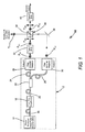
- FIG. 1 schematically illustrates, in block diagram form, one preferred embodiment 10 of a frequency tripled fiber MOPA in accordance with the present invention.
- fiber-optic connections between fiber optic components are depicted by looped double lines. Beams propagating in free-space are depicted by single lines.
- Polarization orientations of radiation are depicted either by a single "end-on" arrowhead (indicating horizontal polarization or polarization perpendicular to the plane of the drawing) or a double-headed arrow (indicating vertical polarization pr polarization parallel to the plane of the drawing).
- Polarization-orientations perpendicular and parallel to the plane of the drawings are referred to arbitrarily herein, for convenience of description, as horizontal and vertical polarization, respectively.
- the two orientations are orthogonal.
- frequency-tripled MOPA includes a seed pulse source 14, preferably a modulated diode-laser.
- the seed-pulse source is connected by an optical fiber 16 to one or more fiber pre-amplification stages 18.
- the output of the preamplifier stage or stages is connected by an optical fiber 20 to a splitter 22.
- Outputs of the splitter are connected by optical fibers 24 and 28 to fiber amplifiers 26 and 30, respectively, each thereof including one or more stages of amplification. It is assumed and preferred, here, that connecting fibers are polarization-maintaining fibers and the preamplifiers include polarization-maintaining gain fibers. In final stages of amplifiers 26 and 30 large mode area (LMA) fibers are preferred.
- LMA large mode area
- the output of seed-pulse source 14 is assumed to be horizontally polarized, and the output of each of amplifiers 26 and 30 is also horizontally polarized as indicated by arrowheads P F1 and P F2 , respectively.
- the fundamental radiation output (Output-1) of amplifier 26 is directed to a second-harmonic generator (2HG) 32 which includes an optically nonlinear crystal (not shown) arranged for type-1 second-harmonic conversion radiation.
- Second harmonic radiation from the type-1 2HG is polarized orthogonal to the input fundamental radiation, i.e., is vertically polarized, as indicated in by arrows P 2H .
- the harmonic conversion in the 2HG is arranged for maximum conversion efficiency, with the crystal preferably being arranged to minimize Poynting vector walk-off between fundamental and 2H-radiations in the crystal of the 2HG. Poynting vector walk-off compensation for collinearly propagating beams is described in detail in U.S. Patent No.
- Conversion efficiency can be as high as about 80% depending on the fundamental wavelength and the material and configuration of the crystal selected.
- This residual fundamental radiation is directed out of fiber-MOPA 10 by reflection from a polarization selective reflecting surface 34 of a bi-prism 36.
- the 2H-radiation being vertically polarized, is transmitted by surface 34.
- the fundamental radiation output of amplifier 30 (Output-2) is directed via a mirror 38 to bi-prism 36 and is reflected from surface 34 thereof collinear with the 2H-radiation transmitted by surface 34.
- the collinear propagating fundamental and 2H-beams are directed to a third-harmonic generator (3HG) 40 which includes an optically nonlinear crystal (also not shown) arranged for type-2 sum-frequency mixing to generate third-harmonic (3H) radiation.
- 3HG third-harmonic generator
- the third-harmonic radiation would have a wavelength in the UV region of the electromagnetic spectrum.
- the division ratio of splitter 22 can be selected based on the gain of amplifiers 26 and 30 and the efficiency of the harmonic generators to minimize residual fundamental and 2H-radiation from the sum-frequency mixing stage. While there will always be some such residual radiation, this radiation can be separated from the 3H output by any well know means.
- each the harmonic generators 32 and 40 would typically include relay optics to focus radiation into the optically nonlinear crystal therein and temperature and environmental controls for the crystal. A detailed description of such optics or controls is not required for understanding the principles of the present invention. Accordingly no such detailed description is presented herein.
- FIG. 2 schematically illustrates a second embodiment 10A of a frequency tripled fiber-MOPA in accordance with the present invention.
- Frequency-tripled fiber-MOPA 10A is similar to frequency-tripled fiber-MOPA 10 of FIG. 1 with exceptions as follows.
- fiber-MOPA 12A delivers from output-1 thereof fundamental radiation which includes both horizontally and vertically polarized components. This is effected by connecting the appropriate output of splitter 22 to amplifier 26 via polarization-maintaining optical fiber 24 and another polarization maintaining fiber 25 with axes thereof at an angle, for example 45°, to corresponding axes of polarization-maintaining fiber 24.
- One other option for creating two polarization components in output-1 is to rotate fiber-axes at about 45 degrees in a fiber coupled isolator (not shown), which typically separates amplification stages in a multi-stage fiber amplifier.
- a fiber coupled isolator not shown
- Those skilled in the art may devise other methods without departing from the spirit and scope of the present invention.
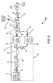
- FIG. 3 schematically illustrates a third embodiment 10B of a frequency tripled fiber-MOPA in accordance with the present invention.
- Frequency-tripled fiber-MOPA 10A is similar to frequency-tripled fiber-MOPA 10 of FIG. 1 with exceptions as follows.
- fiber-MOPA 12B delivers from output-1 thereof fundamental radiation which is vertically polarized (see arrows P F1 ), and delivers from output-2 thereof fundamental radiation which is horizontally polarized (see arrows P F2 ). This is effected, here, by providing a 45°-splice between fibers 20 and 21 connecting preamplifier stage 18 to a fiber polarizing-splitter 22A.
- the splice provides two polarization components, as described above with reference to frequency-tripled MOPA 10A of FIG. 2 , with the components being separated by splitter 22A.
- splitter 22A may derive other methods of providing orthogonally polarized outputs without departing from the spirit and scope of the present invention.
- Second-harmonic generator 32 generates 2H-radiation by type-1 frequency-conversion (type-1 frequency-multiplication) with 2H radiation horizontally polarized as indicated by arrowhead P 2H .
- Surface 34 of bi-prism 36 must be configured here to transmit horizontally polarized 2H-radiation while being polarization-selective for fundamental radiation for reflecting radiation from output 2 of MOPA 12B. Accordingly, if it is necessary to discard fundamental radiation residual from 2HG 32, a separate dichroic element 42 must be provided.
- a third-harmonic generator 40A including an optically nonlinear crystal (not shown) arranged for type-1 sum-frequency mixing, generates 3H-radiation from the identically plane-polarized fundamental and 2H-radiations.
- FIG. 4 schematically illustrates a third embodiment 10C of a frequency tripled fiber-MOPA 10C in accordance with the present invention.
- Frequency-tripled fiber-MOPA 10C is similar to frequency-tripled fiber-MOPA 10B of FIG. 3 with the exception that a MOPA 12C of frequency-tripled fiber-MOPA 10C includes a fiber polarization splitter 22B configured such that fiber-MOPA 12C delivers from output-1 thereof fundamental radiation which is horizontally polarized (see arrows P F1 ), and delivers from output-2 thereof fundamental radiation which is vertically polarized (see arrows P F2 ).
- 2H-radiation generated by 2HG 32 is vertically polarized (see arrows P2H) and is easily transmitted by surface 34 of bi-prism 36. Residual fundamental radiation is horizontally polarized is discarded by surface 34.
- the vertically polarized radiation from output-2 of MOPA 12C is rotated into a horizontally polarized orientation by a half-wave plate 46 and is reflected by surface 34 of bi-prism 36 collinear with the transmitted 2H-radiation.
- the transmitted 2H-radiation and reflected fundamental radiation are sum-frequency mixed by type-2 sum frequency mixing in 3HG 40.
- the plane-polarized seed-pulse source is replaced by an un-polarized or elliptically polarized seed-pulse source.
- the 45-splice would be omitted.
- One such un-polarized seed pulse source could be a fiber laser pumped by a pulsed diode-laser source.
- 3H-generation is effected by delivering fundamental and 2H-radiation beams collinearly to crystal.
- the Poynting vector walk-off compensation disclosure of the above mentioned Nightingale patent is applicable to such 3H-generation in addition to 2H-generation.
- walk-off compensation may be further enhanced by having orthogonally-polarized fundamental and 2H-radiation beams enter a suitably-cut crystal at an angle to each other.
- the 3H-radiation is not generated from residual-fundamental radiation but from fundamental radiation direct from one output of a two-output fiber MOPA. Accordingly, the beam of 2H radiation and the fundamental radiation beam to be mixed are already separated, and can be directly converged into a 3H-generatorarranged as described in the Hoffman et al patent.
- FIG. 5 depicts a frequency-tripled fiber MOPA 10D, which is similar to frequency-tripled fiber MOPA 10 of FIG. 1 except for the manner in which sum-frequency mixing is effected.
- the polarizing bi-prism 36 of frequency-tripled fiber MOPA 10 is omitted and replaced by a dichroic filter 37 arranged to reflect the fundamental wavelength and transmit the second-harmonic radiation to a third-harmonic generator 40B which includes a nonlinear crystal arranged to accept converging fundamental and 2H beams as taught in the Hoffman et al. patent.
- Mirrors 38 and 39 direct the output of amplifier 30 of MOPA 12 into 3HG 40B at the angle ⁇ selected for walk-off optimization.
- ⁇ is about 1°.
- FIG. 5 in addition to providing a possible improvement in 3HG efficiency, eliminates the need for the beam combining arrangements of the frequency tripled MOPAs of FIGS 1-4 .
- This arrangement is not limited for use with the MOPA configuration of FIG. 1 .
- Those skilled in the art may use this type-2 3HG arrangement with other separately-amplified two-output fiber MOPAs without departing from the spirit and scope of the present invention.
Landscapes
- Physics & Mathematics (AREA)
- Nonlinear Science (AREA)
- Electromagnetism (AREA)
- Optics & Photonics (AREA)
- Engineering & Computer Science (AREA)
- Plasma & Fusion (AREA)
- General Physics & Mathematics (AREA)
- Lasers (AREA)
Claims (20)
- Appareil optique, comprenant :un amplificateur MOPA à fibre, le MOPA à fibre comportant un agencement (14, 18) destiné à fournir des impulsions de rayonnement ayant une longueur d'onde fondamentale, un agencement (22, 24, 28) destiné à diviser les impulsions de longueur d'onde fondamentale en première et seconde parties et à diriger les première et seconde parties d'impulsions dans des premier et second canaux de sortie respectifs, et des premier et second amplificateurs à fibre (26, 30) dans les premier et second canaux respectivement destinés à amplifier respectivement les première et seconde parties d'impulsions de longueur d'onde fondamentale ;un agencement (32) destiné à générer des impulsions de rayonnement de deuxième harmonique à partir des parties d'impulsions de longueur d'onde fondamentale amplifiées provenant du premier amplificateur à fibre (26) ; etun agencement (40) destiné à effectuer un mélange somme des fréquences des impulsions de rayonnement de deuxième harmonique et des secondes parties d'impulsions de longueur d'onde fondamentale provenant du second amplificateur à fibre afin de fournir des impulsions de rayonnement de troisième harmonique.
- Appareil selon la revendication 1, dans lequel les première et seconde parties d'impulsions de longueur d'onde fondamentale sont polarisées dans le plan dans la même orientation, la génération de deuxième harmonique est une génération de deuxième harmonique de type 1, et le mélange somme de fréquences est un mélange somme de fréquences de type 2.
- Appareil selon la revendication 1, dans lequel les premières parties d'impulsions de longueur d'onde fondamentale amplifiées ont des composantes de polarisation horizontale et verticale, les parties d'impulsions de longueur d'onde fondamentale amplifiées sont polarisées dans le plan horizontalement, la génération de deuxième harmonique est une génération de deuxième harmonique de type 2, et le mélange somme de fréquences est un mélange somme de fréquences de type 2.
- Appareil selon la revendication 1, dans lequel les premières parties d'impulsions de longueur d'onde fondamentale amplifiées sont polarisées dans le plan verticalement, les parties d'impulsions de longueur d'onde fondamentale amplifiées sont polarisées dans le plan horizontalement, la génération de deuxième harmonique est une génération de deuxième harmonique de type 1, et le mélange somme de fréquences est un mélange somme de fréquences de type 1.
- Appareil selon la revendication 1, dans lequel un dispositif de rotation de polarisation (46) est placé entre le second amplificateur à fibre (30) et l'agencement de génération de troisième harmonique (40), les premières parties d'impulsions de longueur d'onde fondamentale amplifiées sont polarisées dans le plan horizontalement, les secondes parties d'impulsions de longueur d'onde fondamentale amplifiées sont polarisées dans le plan verticalement à leur sortie du second amplificateur à fibre (30), le dispositif de rotation de polarisation (46) étant configuré pour tourner l'orientation verticale des secondes parties d'impulsions de longueur d'onde fondamentale amplifiées en une orientation horizontale, la génération de deuxième harmonique est une génération de deuxième harmonique de type 1, et le mélange somme de fréquences est un mélange somme de fréquences de type 2.
- Appareil selon la revendication 1, comportant un agencement (34) pour combiner les impulsions de rayonnement de deuxième harmonique et les secondes parties d'impulsions de longueur d'onde fondamentale amplifiées sur un chemin commun vers l'agencement de mélange somme de fréquences.
- Appareil selon la revendication 1, dans lequel des parties résiduelles des parties d'impulsions de longueur d'onde fondamentale amplifiées provenant du premier amplificateur à fibre (26) demeurent après le processus de génération de deuxième harmonique, et l'appareil comportant des moyens (36 ; 37) pour empêcher les parties résiduelles d'entrer dans l'agencement de génération de fréquence somme (40 ; 40A ; 40B).
- Appareil selon la revendication 1, dans lequel les impulsions de rayonnement de deuxième harmonique et les secondes parties d'impulsions de longueur d'onde fondamentale amplifiées provenant du second amplificateur à fibre (30) sont dirigées dans l'agencement de mélange somme de fréquences (40B) sur respectivement des premier et second chemins situés à un certain angle l'un par rapport à l'autre.
- Appareil selon la revendication 8, dans lequel l'angle entre les premier et second chemins est sélectionné en coopération avec l'agencement de génération de fréquence somme pour minimiser la dérive de vecteur Poynting dans le processus de génération de fréquence somme.
- Appareil selon la revendication 1, dans lequel une surface réfléchissante et transmissive à polarisation sélective (34) est agencée pour amener les impulsions de rayonnement de deuxième harmonique et les secondes parties d'impulsions de longueur d'onde fondamentale amplifiées provenant du second amplificateur à fibre à se propager colinéairement le long d'un chemin commun.
- Appareil selon la revendication 10, dans lequel la surface réfléchissante et transmissive à polarisation sélective (34) est une surface interne d'un biprisme (36).
- Appareil selon la revendication 10, dans lequel les premières et secondes parties d'impulsions de longueur d'onde fondamentale amplifiées sont chacune polarisées horizontalement, les impulsions de rayonnement de deuxième harmonique sont polarisées verticalement, la surface réfléchissante et transmissive à polarisation sélective (34) réfléchit un rayonnement fondamental polarisé horizontalement et transmet un rayonnement fondamental polarisé verticalement, et la surface réfléchissante et transmissive à polarisation sélective (34) transmet les impulsions de rayonnement de deuxième harmonique le long du chemin commun et réfléchit les secondes parties d'impulsions de longueur d'onde fondamentale amplifiées le long du chemin commun.
- Appareil selon la revendication 12, dans lequel des parties résiduelles des impulsions de longueur d'onde fondamentale amplifiées provenant du premier amplificateur à fibre (26) demeurent après le processus de génération de deuxième harmonique, et la surface réfléchissante et transmissive à polarisation sélective (34) réfléchit ces parties résiduelles des impulsions de longueur d'onde fondamentales à l'écart de l'agencement de mélange somme de fréquences (40).
- Appareil selon la revendication 10, dans lequel les premières parties d'impulsions de longueur d'onde fondamentale amplifiées ont des composantes de polarisation horizontale et verticale, les secondes parties d'impulsions de longueur d'onde fondamentale amplifiées sont polarisées dans le plan horizontalement, les impulsions de deuxième harmonique sont polarisées verticalement, la surface réfléchissante et transmissive à polarisation sélective (34) réfléchit un rayonnement fondamental polarisé horizontalement et transmet un rayonnement de deuxième harmonique, et la surface réfléchissante et transmissive à polarisation sélective (34) transmet les impulsions de rayonnement de deuxième harmonique le long du chemin commun et réfléchit les secondes parties d'impulsions de longueur d'onde fondamentale amplifiées le long du chemin commun.
- Appareil selon la revendication 10, dans lequel les premières parties d'impulsions de longueur d'onde fondamentale amplifiées sont chacune polarisées dans le plan verticalement, les secondes parties d'impulsions amplifiées sont polarisées dans le plan horizontalement, les impulsions de deuxième harmonique sont polarisées horizontalement, la surface réfléchissante et transmissive à polarisation sélective (34) réfléchit un rayonnement fondamental polarisé horizontalement et transmet un rayonnement fondamental polarisé verticalement et un rayonnement fondamental polarisé horizontalement, et la surface réfléchissante et transmissive à polarisation sélective (34) transmet les impulsions de rayonnement de deuxième harmonique le long du chemin commun et réfléchit les secondes parties d'impulsions de longueur d'onde fondamentale amplifiées le long du chemin commun.
- Appareil selon la revendication 15, dans lequel des parties résiduelles des impulsions de longueur d'onde fondamentale amplifiées provenant du premier amplificateur à fibre demeurent après le processus de génération de deuxième harmonique, dans lequel la surface réfléchissante et transmissive à polarisation sélective (34) transmet ces parties résiduelles des impulsions de longueur d'onde fondamentale amplifiées le long du chemin commun, et un réflecteur sélectif en longueur d'onde (42) est placé dans le chemin commun et agencé pour réfléchir ces parties résiduelles à l'écart de l'agencement de mélange somme de fréquences.
- Procédé de génération d'impulsions de troisième harmonique comprenant les étapes consistant à :générer des impulsions laser fondamentales à partir d'un oscillateur maître ;diviser chacune des impulsions entre des premier et second canaux de propagation ;amplifier par fibre les impulsions fondamentales dans le premier canal ;convertir en fréquence les impulsions fondamentales amplifiées dans le premier canal en impulsions de deuxième harmonique ; eteffectuer un mélange somme de fréquences des impulsions de deuxième harmonique et des impulsions fondamentales amplifiées du second canal afin de générer des impulsions de troisième harmonique.
- Procédé selon la revendication 17, dans lequel l'étape de conversion de fréquence est de type 1 et l'étape de mélange somme de fréquence est de type 2.
- Procédé selon la revendication 17, dans lequel l'étape de conversion de fréquence est de type 2 et l'étape de mélange somme de fréquences est de type 2.
- Procédé selon la revendication 17, dans lequel l'étape de conversion de fréquence est de type 1 et l'étape de mélange somme de fréquences est de type 1.
Applications Claiming Priority (2)
| Application Number | Priority Date | Filing Date | Title |
|---|---|---|---|
| US12/335,015 US7920606B2 (en) | 2008-12-15 | 2008-12-15 | Frequency-tripled fiber MOPA |
| PCT/US2009/065579 WO2010074869A1 (fr) | 2008-12-15 | 2009-11-23 | Maître oscillateur et amplificateur de puissance (mopa) à fibres triplé en fréquence |
Publications (2)
| Publication Number | Publication Date |
|---|---|
| EP2376980A1 EP2376980A1 (fr) | 2011-10-19 |
| EP2376980B1 true EP2376980B1 (fr) | 2012-10-03 |
Family
ID=41511092
Family Applications (1)
| Application Number | Title | Priority Date | Filing Date |
|---|---|---|---|
| EP09756937A Not-in-force EP2376980B1 (fr) | 2008-12-15 | 2009-11-23 | Maître oscillateur et amplificateur de puissance (mopa) à fibres triplé en fréquence |
Country Status (3)
| Country | Link |
|---|---|
| US (1) | US7920606B2 (fr) |
| EP (1) | EP2376980B1 (fr) |
| WO (1) | WO2010074869A1 (fr) |
Cited By (2)
| Publication number | Priority date | Publication date | Assignee | Title |
|---|---|---|---|---|
| CN107086430A (zh) * | 2017-06-09 | 2017-08-22 | 武汉安扬激光技术有限责任公司 | 一种三倍频紫外激光器 |
| US12517237B1 (en) * | 2022-06-24 | 2026-01-06 | Aurora Operations, Inc | LIDAR sensor system including polarizer optics |
Families Citing this family (16)
| Publication number | Priority date | Publication date | Assignee | Title |
|---|---|---|---|---|
| US20110069376A1 (en) * | 2009-09-23 | 2011-03-24 | Coherent Inc. | Fiber mopa with amplifying transport fiber |
| CN102208747B (zh) * | 2011-05-09 | 2013-06-05 | 中国电子科技集团公司第十一研究所 | 一种固体激光器 |
| US8373924B2 (en) | 2011-05-25 | 2013-02-12 | Coherent, Inc. | Frequency-tripled fiber MOPA |
| CN102447212B (zh) * | 2011-12-06 | 2013-05-08 | 中国科学院上海光学精密机械研究所 | 脉冲光纤放大器阵列光反馈环形腔相干组束系统 |
| US8582611B2 (en) * | 2012-01-20 | 2013-11-12 | Coherent, Inc. | Frequency-tripled fiber-MOPA |
| WO2014025906A1 (fr) * | 2012-08-07 | 2014-02-13 | Ipg Photonics Corporation | Système de laser à fibre multi-kilowatts, léger, ultra-compact et de forte puissance basé sur un mélange de faisceaux cohérents et spectraux |
| FR3004820B1 (fr) | 2013-04-19 | 2016-08-19 | Centre Nat Rech Scient | Generateur de faisceaux laser coherents infrarouge et visible. |
| CN103545706B (zh) * | 2013-09-02 | 2018-06-22 | 长春理工大学 | 一种全固态355nm激光器 |
| CN104577663A (zh) * | 2013-10-22 | 2015-04-29 | 无锡津天阳激光电子有限公司 | 一种风速仪用三端输出532nm与660nm与808nm三波长光纤激光器 |
| CN104577661A (zh) * | 2013-10-22 | 2015-04-29 | 无锡津天阳激光电子有限公司 | 一种风速仪用三端输出双1064nm与808nm波长光纤激光器 |
| CN104577662A (zh) * | 2013-10-22 | 2015-04-29 | 无锡津天阳激光电子有限公司 | 一种风速仪用三端输出双1319nm与808nm波长光纤激光器 |
| FR3023423B1 (fr) * | 2014-07-03 | 2016-07-08 | Amplitude Systemes | Systeme laser uv-visible a impulsions ultra-courtes de forte puissance et/ou de forte energie |
| CN108169229B (zh) * | 2016-12-07 | 2020-06-02 | 北京大学 | 一种基于径向偏振光束的手性和频产生显微镜及成像方法 |
| CN108649419A (zh) * | 2018-03-02 | 2018-10-12 | 上海交通大学 | 超高平均功率光参量啁啾脉冲放大器 |
| DE102019131827B4 (de) * | 2019-11-25 | 2021-12-23 | Novanta Europe Gmbh | Frequenzkonversionsanordnung zur Optimierung von Eigenschaften einer Harmonischen eines Lasers |
| EP3926824A1 (fr) | 2020-06-17 | 2021-12-22 | Imec VZW | Dispositif et procédé de génération d'harmoniques impaires |
Family Cites Families (9)
| Publication number | Priority date | Publication date | Assignee | Title |
|---|---|---|---|---|
| US5136597A (en) * | 1991-03-15 | 1992-08-04 | Coherent, Inc. | Poynting vector walk-off compensation in type ii phasematching |
| US5341236A (en) | 1992-12-03 | 1994-08-23 | Northrop Corporation | Nonlinear optical wavelength converters with feedback |
| US5867305A (en) * | 1996-01-19 | 1999-02-02 | Sdl, Inc. | Optical amplifier with high energy levels systems providing high peak powers |
| US5940418A (en) * | 1996-06-13 | 1999-08-17 | Jmar Technology Co. | Solid-state laser system for ultra-violet micro-lithography |
| US7292387B2 (en) * | 2005-01-12 | 2007-11-06 | Spectra-Physics, Inc. | Methods and systems to enhance multiple wave mixing process |
| US7593440B2 (en) | 2005-03-29 | 2009-09-22 | Coherent, Inc. | MOPA laser apparatus with two master oscillators for generating ultraviolet radiation |
| US7471705B2 (en) * | 2005-11-09 | 2008-12-30 | Lockheed Martin Corporation | Ultraviolet laser system and method having wavelength in the 200-nm range |
| US20070263680A1 (en) | 2006-05-15 | 2007-11-15 | Andrei Starodoumov | MOPA laser apparatus with two master oscillators for generating ultraviolet radiation |
| US7593437B2 (en) | 2006-05-15 | 2009-09-22 | Coherent, Inc. | MOPA laser apparatus with two master oscillators for generating ultraviolet radiation |
-
2008
- 2008-12-15 US US12/335,015 patent/US7920606B2/en not_active Expired - Fee Related
-
2009
- 2009-11-23 EP EP09756937A patent/EP2376980B1/fr not_active Not-in-force
- 2009-11-23 WO PCT/US2009/065579 patent/WO2010074869A1/fr not_active Ceased
Cited By (3)
| Publication number | Priority date | Publication date | Assignee | Title |
|---|---|---|---|---|
| CN107086430A (zh) * | 2017-06-09 | 2017-08-22 | 武汉安扬激光技术有限责任公司 | 一种三倍频紫外激光器 |
| CN107086430B (zh) * | 2017-06-09 | 2019-05-10 | 武汉安扬激光技术有限责任公司 | 一种三倍频紫外激光器 |
| US12517237B1 (en) * | 2022-06-24 | 2026-01-06 | Aurora Operations, Inc | LIDAR sensor system including polarizer optics |
Also Published As
| Publication number | Publication date |
|---|---|
| EP2376980A1 (fr) | 2011-10-19 |
| US20100150183A1 (en) | 2010-06-17 |
| US7920606B2 (en) | 2011-04-05 |
| WO2010074869A1 (fr) | 2010-07-01 |
Similar Documents
| Publication | Publication Date | Title |
|---|---|---|
| EP2376980B1 (fr) | Maître oscillateur et amplificateur de puissance (mopa) à fibres triplé en fréquence | |
| US8373924B2 (en) | Frequency-tripled fiber MOPA | |
| US7443903B2 (en) | Laser apparatus having multiple synchronous amplifiers tied to one master oscillator | |
| JP5269764B2 (ja) | パルス動作uv及び可視ラマンレーザシステム | |
| US20090185583A1 (en) | UV and Visible Laser Systems | |
| US10014652B2 (en) | Broadly tunable optical parametric oscillator | |
| CN112385098A (zh) | 激光束方法和系统 | |
| JP2016532882A (ja) | 円形出力ビーム用の高効率単一パス高調波発生器 | |
| KR20130119416A (ko) | 자외 레이저 장치 | |
| JP2015222425A (ja) | カスケード光高調波発生 | |
| US6775053B2 (en) | High gain preamplifier based on optical parametric amplification | |
| US10720749B2 (en) | Generation of frequency-tripled laser radiation | |
| CN219123662U (zh) | 一种皮秒紫外激光器 | |
| US20090180498A1 (en) | Coherent Beam Combiner Based on Parametric Conversion | |
| US20240235145A9 (en) | Divided-pulse laser regeneration amplification apparatus and method | |
| US8582611B2 (en) | Frequency-tripled fiber-MOPA | |
| US10642127B1 (en) | Single Crystal optical parametric amplifier | |
| CN111711058A (zh) | 一种基于Mamyshev振荡器差频的紧凑型可调谐红外激光器 | |
| CN111404011A (zh) | 一种高次谐波激光器 | |
| Mu et al. | High efficiency fourth-harmonic generation from nanosecond fiber master oscillator power amplifier | |
| US7463410B2 (en) | Optical frequency converter for non-polarized light | |
| CN120033518B (zh) | 一种基于光谱整形的短脉冲再生放大器 | |
| WO2011123822A2 (fr) | Appareil et procédé de génération de lumière ultraviolette à onde entretenue | |
| Edelmann et al. | Fiber-Interferometric Second Harmonic Generator for Dual-Color Standard Quantum-limited Noise Suppression | |
| Vidal et al. | High power continuous laser at 461 nm based on a frequency-doubling linear cavity |
Legal Events
| Date | Code | Title | Description |
|---|---|---|---|
| PUAI | Public reference made under article 153(3) epc to a published international application that has entered the european phase |
Free format text: ORIGINAL CODE: 0009012 |
|
| 17P | Request for examination filed |
Effective date: 20110711 |
|
| AK | Designated contracting states |
Kind code of ref document: A1 Designated state(s): AT BE BG CH CY CZ DE DK EE ES FI FR GB GR HR HU IE IS IT LI LT LU LV MC MK MT NL NO PL PT RO SE SI SK SM TR |
|
| RIN1 | Information on inventor provided before grant (corrected) |
Inventor name: SIMANOVSKI, DMITRI Inventor name: AUSTIN, R., RUSSEL Inventor name: HODGSON, NORMAN Inventor name: STARODOUMOV, ANDREI |
|
| DAX | Request for extension of the european patent (deleted) | ||
| GRAP | Despatch of communication of intention to grant a patent |
Free format text: ORIGINAL CODE: EPIDOSNIGR1 |
|
| GRAS | Grant fee paid |
Free format text: ORIGINAL CODE: EPIDOSNIGR3 |
|
| GRAA | (expected) grant |
Free format text: ORIGINAL CODE: 0009210 |
|
| RIN1 | Information on inventor provided before grant (corrected) |
Inventor name: AUSTIN, R., RUSSEL Inventor name: STARODOUMOV, ANDREI Inventor name: SIMANOVSKI, DMITRI Inventor name: HODGSON, NORMAN |
|
| AK | Designated contracting states |
Kind code of ref document: B1 Designated state(s): AT BE BG CH CY CZ DE DK EE ES FI FR GB GR HR HU IE IS IT LI LT LU LV MC MK MT NL NO PL PT RO SE SI SK SM TR |
|
| REG | Reference to a national code |
Ref country code: GB Ref legal event code: FG4D |
|
| REG | Reference to a national code |
Ref country code: AT Ref legal event code: REF Ref document number: 578229 Country of ref document: AT Kind code of ref document: T Effective date: 20121015 Ref country code: CH Ref legal event code: EP |
|
| REG | Reference to a national code |
Ref country code: IE Ref legal event code: FG4D |
|
| REG | Reference to a national code |
Ref country code: DE Ref legal event code: R096 Ref document number: 602009010216 Country of ref document: DE Effective date: 20121129 |
|
| REG | Reference to a national code |
Ref country code: AT Ref legal event code: MK05 Ref document number: 578229 Country of ref document: AT Kind code of ref document: T Effective date: 20121003 |
|
| PG25 | Lapsed in a contracting state [announced via postgrant information from national office to epo] |
Ref country code: SI Free format text: LAPSE BECAUSE OF FAILURE TO SUBMIT A TRANSLATION OF THE DESCRIPTION OR TO PAY THE FEE WITHIN THE PRESCRIBED TIME-LIMIT Effective date: 20121003 |
|
| REG | Reference to a national code |
Ref country code: NL Ref legal event code: VDEP Effective date: 20121003 |
|
| REG | Reference to a national code |
Ref country code: LT Ref legal event code: MG4D |
|
| PG25 | Lapsed in a contracting state [announced via postgrant information from national office to epo] |
Ref country code: IS Free format text: LAPSE BECAUSE OF FAILURE TO SUBMIT A TRANSLATION OF THE DESCRIPTION OR TO PAY THE FEE WITHIN THE PRESCRIBED TIME-LIMIT Effective date: 20130203 Ref country code: HR Free format text: LAPSE BECAUSE OF FAILURE TO SUBMIT A TRANSLATION OF THE DESCRIPTION OR TO PAY THE FEE WITHIN THE PRESCRIBED TIME-LIMIT Effective date: 20121003 Ref country code: NL Free format text: LAPSE BECAUSE OF FAILURE TO SUBMIT A TRANSLATION OF THE DESCRIPTION OR TO PAY THE FEE WITHIN THE PRESCRIBED TIME-LIMIT Effective date: 20121003 Ref country code: SE Free format text: LAPSE BECAUSE OF FAILURE TO SUBMIT A TRANSLATION OF THE DESCRIPTION OR TO PAY THE FEE WITHIN THE PRESCRIBED TIME-LIMIT Effective date: 20121003 Ref country code: NO Free format text: LAPSE BECAUSE OF FAILURE TO SUBMIT A TRANSLATION OF THE DESCRIPTION OR TO PAY THE FEE WITHIN THE PRESCRIBED TIME-LIMIT Effective date: 20130103 Ref country code: LT Free format text: LAPSE BECAUSE OF FAILURE TO SUBMIT A TRANSLATION OF THE DESCRIPTION OR TO PAY THE FEE WITHIN THE PRESCRIBED TIME-LIMIT Effective date: 20121003 Ref country code: FI Free format text: LAPSE BECAUSE OF FAILURE TO SUBMIT A TRANSLATION OF THE DESCRIPTION OR TO PAY THE FEE WITHIN THE PRESCRIBED TIME-LIMIT Effective date: 20121003 |
|
| PG25 | Lapsed in a contracting state [announced via postgrant information from national office to epo] |
Ref country code: BE Free format text: LAPSE BECAUSE OF FAILURE TO SUBMIT A TRANSLATION OF THE DESCRIPTION OR TO PAY THE FEE WITHIN THE PRESCRIBED TIME-LIMIT Effective date: 20121003 Ref country code: LV Free format text: LAPSE BECAUSE OF FAILURE TO SUBMIT A TRANSLATION OF THE DESCRIPTION OR TO PAY THE FEE WITHIN THE PRESCRIBED TIME-LIMIT Effective date: 20121003 Ref country code: GR Free format text: LAPSE BECAUSE OF FAILURE TO SUBMIT A TRANSLATION OF THE DESCRIPTION OR TO PAY THE FEE WITHIN THE PRESCRIBED TIME-LIMIT Effective date: 20130104 Ref country code: PT Free format text: LAPSE BECAUSE OF FAILURE TO SUBMIT A TRANSLATION OF THE DESCRIPTION OR TO PAY THE FEE WITHIN THE PRESCRIBED TIME-LIMIT Effective date: 20130204 Ref country code: PL Free format text: LAPSE BECAUSE OF FAILURE TO SUBMIT A TRANSLATION OF THE DESCRIPTION OR TO PAY THE FEE WITHIN THE PRESCRIBED TIME-LIMIT Effective date: 20121003 |
|
| PG25 | Lapsed in a contracting state [announced via postgrant information from national office to epo] |
Ref country code: AT Free format text: LAPSE BECAUSE OF FAILURE TO SUBMIT A TRANSLATION OF THE DESCRIPTION OR TO PAY THE FEE WITHIN THE PRESCRIBED TIME-LIMIT Effective date: 20121003 |
|
| PG25 | Lapsed in a contracting state [announced via postgrant information from national office to epo] |
Ref country code: CZ Free format text: LAPSE BECAUSE OF FAILURE TO SUBMIT A TRANSLATION OF THE DESCRIPTION OR TO PAY THE FEE WITHIN THE PRESCRIBED TIME-LIMIT Effective date: 20121003 Ref country code: DK Free format text: LAPSE BECAUSE OF FAILURE TO SUBMIT A TRANSLATION OF THE DESCRIPTION OR TO PAY THE FEE WITHIN THE PRESCRIBED TIME-LIMIT Effective date: 20121003 Ref country code: SK Free format text: LAPSE BECAUSE OF FAILURE TO SUBMIT A TRANSLATION OF THE DESCRIPTION OR TO PAY THE FEE WITHIN THE PRESCRIBED TIME-LIMIT Effective date: 20121003 Ref country code: BG Free format text: LAPSE BECAUSE OF FAILURE TO SUBMIT A TRANSLATION OF THE DESCRIPTION OR TO PAY THE FEE WITHIN THE PRESCRIBED TIME-LIMIT Effective date: 20130103 Ref country code: EE Free format text: LAPSE BECAUSE OF FAILURE TO SUBMIT A TRANSLATION OF THE DESCRIPTION OR TO PAY THE FEE WITHIN THE PRESCRIBED TIME-LIMIT Effective date: 20121003 |
|
| PLBE | No opposition filed within time limit |
Free format text: ORIGINAL CODE: 0009261 |
|
| STAA | Information on the status of an ep patent application or granted ep patent |
Free format text: STATUS: NO OPPOSITION FILED WITHIN TIME LIMIT |
|
| REG | Reference to a national code |
Ref country code: IE Ref legal event code: MM4A |
|
| PG25 | Lapsed in a contracting state [announced via postgrant information from national office to epo] |
Ref country code: IT Free format text: LAPSE BECAUSE OF FAILURE TO SUBMIT A TRANSLATION OF THE DESCRIPTION OR TO PAY THE FEE WITHIN THE PRESCRIBED TIME-LIMIT Effective date: 20121003 Ref country code: RO Free format text: LAPSE BECAUSE OF FAILURE TO SUBMIT A TRANSLATION OF THE DESCRIPTION OR TO PAY THE FEE WITHIN THE PRESCRIBED TIME-LIMIT Effective date: 20121003 |
|
| 26N | No opposition filed |
Effective date: 20130704 |
|
| PG25 | Lapsed in a contracting state [announced via postgrant information from national office to epo] |
Ref country code: ES Free format text: LAPSE BECAUSE OF FAILURE TO SUBMIT A TRANSLATION OF THE DESCRIPTION OR TO PAY THE FEE WITHIN THE PRESCRIBED TIME-LIMIT Effective date: 20130114 Ref country code: IE Free format text: LAPSE BECAUSE OF NON-PAYMENT OF DUE FEES Effective date: 20121123 |
|
| REG | Reference to a national code |
Ref country code: DE Ref legal event code: R097 Ref document number: 602009010216 Country of ref document: DE Effective date: 20130704 |
|
| PG25 | Lapsed in a contracting state [announced via postgrant information from national office to epo] |
Ref country code: MT Free format text: LAPSE BECAUSE OF FAILURE TO SUBMIT A TRANSLATION OF THE DESCRIPTION OR TO PAY THE FEE WITHIN THE PRESCRIBED TIME-LIMIT Effective date: 20121003 Ref country code: CY Free format text: LAPSE BECAUSE OF FAILURE TO SUBMIT A TRANSLATION OF THE DESCRIPTION OR TO PAY THE FEE WITHIN THE PRESCRIBED TIME-LIMIT Effective date: 20121003 |
|
| PG25 | Lapsed in a contracting state [announced via postgrant information from national office to epo] |
Ref country code: MC Free format text: LAPSE BECAUSE OF NON-PAYMENT OF DUE FEES Effective date: 20121130 Ref country code: TR Free format text: LAPSE BECAUSE OF FAILURE TO SUBMIT A TRANSLATION OF THE DESCRIPTION OR TO PAY THE FEE WITHIN THE PRESCRIBED TIME-LIMIT Effective date: 20121003 |
|
| PG25 | Lapsed in a contracting state [announced via postgrant information from national office to epo] |
Ref country code: SM Free format text: LAPSE BECAUSE OF FAILURE TO SUBMIT A TRANSLATION OF THE DESCRIPTION OR TO PAY THE FEE WITHIN THE PRESCRIBED TIME-LIMIT Effective date: 20121003 Ref country code: LU Free format text: LAPSE BECAUSE OF NON-PAYMENT OF DUE FEES Effective date: 20121123 |
|
| REG | Reference to a national code |
Ref country code: CH Ref legal event code: PL |
|
| PG25 | Lapsed in a contracting state [announced via postgrant information from national office to epo] |
Ref country code: LI Free format text: LAPSE BECAUSE OF NON-PAYMENT OF DUE FEES Effective date: 20131130 Ref country code: CH Free format text: LAPSE BECAUSE OF NON-PAYMENT OF DUE FEES Effective date: 20131130 Ref country code: HU Free format text: LAPSE BECAUSE OF FAILURE TO SUBMIT A TRANSLATION OF THE DESCRIPTION OR TO PAY THE FEE WITHIN THE PRESCRIBED TIME-LIMIT Effective date: 20091123 |
|
| PG25 | Lapsed in a contracting state [announced via postgrant information from national office to epo] |
Ref country code: MK Free format text: LAPSE BECAUSE OF FAILURE TO SUBMIT A TRANSLATION OF THE DESCRIPTION OR TO PAY THE FEE WITHIN THE PRESCRIBED TIME-LIMIT Effective date: 20121003 |
|
| REG | Reference to a national code |
Ref country code: FR Ref legal event code: PLFP Year of fee payment: 7 |
|
| REG | Reference to a national code |
Ref country code: FR Ref legal event code: PLFP Year of fee payment: 8 |
|
| REG | Reference to a national code |
Ref country code: FR Ref legal event code: PLFP Year of fee payment: 9 |
|
| REG | Reference to a national code |
Ref country code: FR Ref legal event code: PLFP Year of fee payment: 10 |
|
| PGFP | Annual fee paid to national office [announced via postgrant information from national office to epo] |
Ref country code: DE Payment date: 20191112 Year of fee payment: 11 |
|
| PGFP | Annual fee paid to national office [announced via postgrant information from national office to epo] |
Ref country code: FR Payment date: 20191014 Year of fee payment: 11 |
|
| PGFP | Annual fee paid to national office [announced via postgrant information from national office to epo] |
Ref country code: GB Payment date: 20191122 Year of fee payment: 11 |
|
| REG | Reference to a national code |
Ref country code: DE Ref legal event code: R119 Ref document number: 602009010216 Country of ref document: DE |
|
| GBPC | Gb: european patent ceased through non-payment of renewal fee |
Effective date: 20201123 |
|
| PG25 | Lapsed in a contracting state [announced via postgrant information from national office to epo] |
Ref country code: FR Free format text: LAPSE BECAUSE OF NON-PAYMENT OF DUE FEES Effective date: 20201130 |
|
| PG25 | Lapsed in a contracting state [announced via postgrant information from national office to epo] |
Ref country code: GB Free format text: LAPSE BECAUSE OF NON-PAYMENT OF DUE FEES Effective date: 20201123 Ref country code: DE Free format text: LAPSE BECAUSE OF NON-PAYMENT OF DUE FEES Effective date: 20210601 |